![]()
Installation Instructions
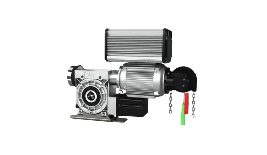
ELEKTROMAT
KE 40.40 FU-40,00
Model: 10003840 10812
Status: 19.01.2022
GfA ELEKTROMATEN GmbH & Co. KG
Wiesenstraße 81
D-40549 Düsseldorf![]() www.gfa-elektromaten.de
www.gfa-elektromaten.de![]() [email protected]
[email protected]
Symbols
![]() Warning – Potential injury or danger to life!
Warning – Potential injury or danger to life!![]() Warning – Danger to life from electric current!
Warning – Danger to life from electric current!![]() Note – Important information!
Note – Important information!![]() Requirement – Required action!
Requirement – Required action!
Schematic representations are based on product examples. Deviations from delivered products are possible.
1 General safety information
Specified use
The drive unit is intended for vertically moving doors. The force is transmitted using a chain. Doors that must be secured against dropping require a separate safety brake. The drive unit must be protected against moisture and aggressive environmental conditions (such as corrosive substances). The drive units are only suitable for indoor use. Appropriate protective measures must be taken for outdoor installation. The drive unit is not intended for hazardous areas. The values specified in the technical data of the drive unit must not be exceeded. The safe operation can only be ensured if used as specified.
Target audience of these installation instructions
These installation instructions are geared towards qualified persons trained in the handling of door systems. Expert knowledge, relevant skills and practical experience are what set apart qualified persons. They are capable of safely carrying out the tasks involving installation, maintenance and modernisation according to the instructions.
Safe operation
The safe operation of the product can only be ensured if it is used as specified. Follow the installation instructions. Observe all specifications, especially warnings, when installing the product in the overall system. GfA is not liable for damage resulting from non-observance of the installation instructions. The resulting overall system must be reassessed for its safety in accordance with applicable standards and directives (e.g. CE marking). These installation instructions refer only to a part of the overall system and are not sufficient as the sole instructions for the overall system. The installer of the system must prepare the instructions for the overall system. We recommend entering the danger area of the system only when the drive unit is at a standstill.
![]() Warning – Failure to follow these installation instructions may result in severe injury or death.
Warning – Failure to follow these installation instructions may result in severe injury or death.
- Please read these instructions before using the product.
- Keep these instructions handy.
- Include these instructions when passing on the product to third parties.
![]() Warning – Danger from improper use of the product!
Warning – Danger from improper use of the product!
- Do not let children operate the product unsupervised or use as a toy.
![]() Warning – Danger to life from incorrect installation!
Warning – Danger to life from incorrect installation!
Work carried out improperly may result in death or severe injury from electrical current or falling parts.
- Allow only competent people to carry out the work.
- Disconnect all cables from the power supply.
- Observe valid regulations and standards.
- Use suitable tools.
![]() Warning! Danger to life from falling objects if the drive unit is subjected to impermissible forces.
Warning! Danger to life from falling objects if the drive unit is subjected to impermissible forces.
Inadmissible forces (examples: collision with a forklift, dropping the drive unit, tearing or pulling on the motor) lead to damage to the drive unit. There is a risk of severe injury or death from falling objects.
- Prevent impermissible forces from acting on the drive unit,
- Check the drive unit for damage if impermissible forces have acted on it. Look even for minor damage. Lock the door during the inspection.
- Contact the service department if you have difficulty assessing the damage.
2 Technical data
| Designation | Unit | |
| Output speed | 40 | rpm |
| Output torque | 400 (310) 1) | Nm |
| Output / hollow shaft | 40,00 | mm |
| Series | SG 85 | – |
| Limit switch range (maximum revolutions of the output / hollow shaft) | 20 | – |
| Supply voltage | 1N~ 230 | V |
| Operating current | 7,30 | A |
| Operating frequency | 50/60 | Hz |
| Power factor cos φ | 0,63 | – |
| Safety circuit | 24 | V |
| Degree of protection | IP 65 | – |
| Temperature range | +5 / +40 (+60) 2) | °C |
| Operating sound pressure level | < 70 | dB(A) |
| Output speed OPEN | 9-40 | min-1 |
| Output speed CLOSE | 9-24 | min-1 |
| Output speed CLOSE > 2,5 m | 9-35 | min-1 |
| Cycles per hour | 17 (16,4)1) | h-1 |
| Max. holding torque | 400 | Nm |
| Braking torque | 9 | Nm |
| Braking voltage | 103 | V DC |
| Rectifier type | FU | – |
| Manual force emergency manual operation | 126 | N |
1) Specification in ( ) according to EN 60335-2-103
2) When using a temperature range of +40°…+60°C use half of maximum cycles per hour.
3 Mechanical installation
Prerequisites
The permissible loads on walls, fastenings, mountings and transmission elements must not be exceeded, even for maximum holding torques or locking torques ( refer to technical data).
Connection elements
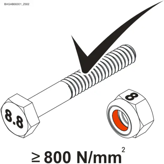
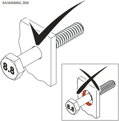
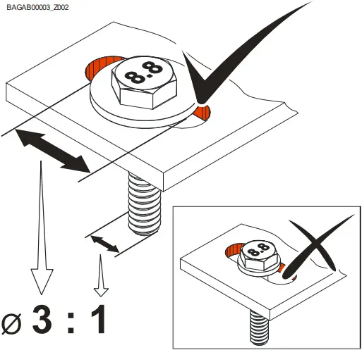
| • Self-locking connection elements with a minimum strength of 800 N/mm2 (8.8) must be used. | • Utilize the hole diameter to the full. | • Use adequately dimensioned washers for elongated holes. |
 |  |  |
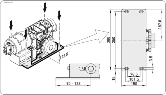
Permissible mounting positions
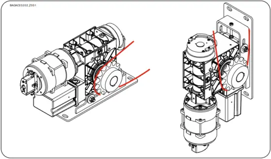
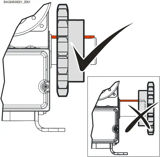
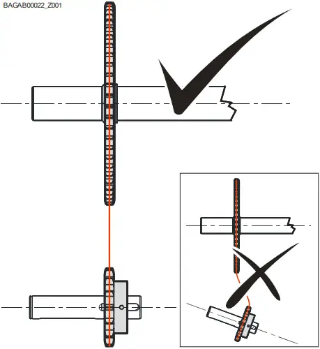
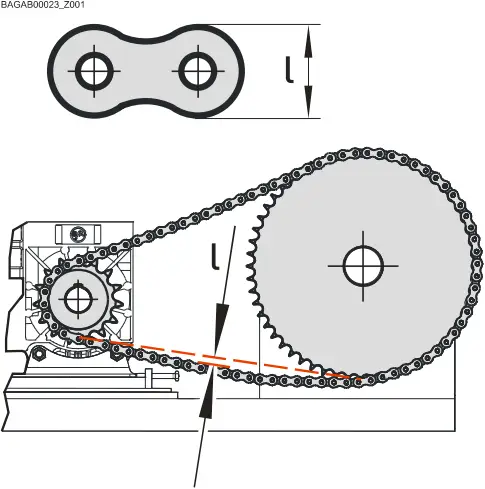
Transmission elements
| • Install the chain wheel properly. | • Position the chain wheels properly. | • Tighten the chain wheel properly. |
 |  |  |
Mounting
Four elongated holes are provided for mounting.
Installation
The descriptions below apply to general door specifications. The specifications of the door manufacturer must also be observed during installation.
![]() Warning – Potential injury or danger to life!
Warning – Potential injury or danger to life!
- During installation, be sure to use a lifting device that has a sufficient loadcarrying capacity.
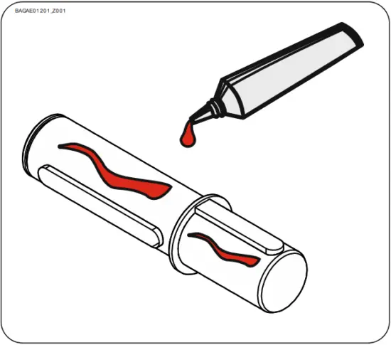
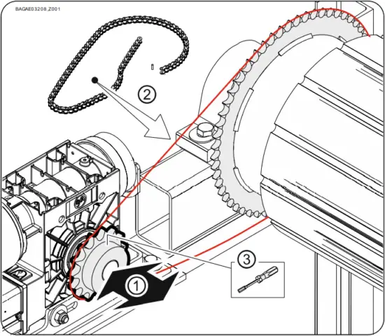
• Thoroughly grease the output-shaft.
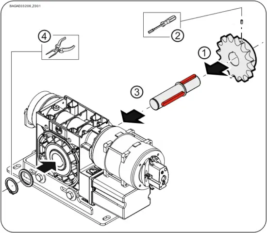
• Install (1) and secure (2) the chain wheel. Do not tighten yet. Install (3) and secure (4) the output-shaft on the right or left.
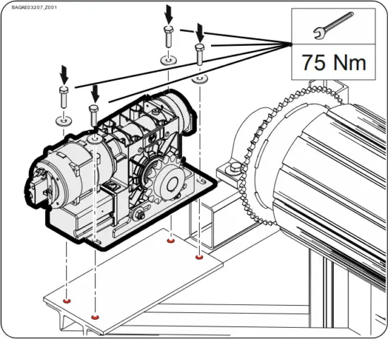
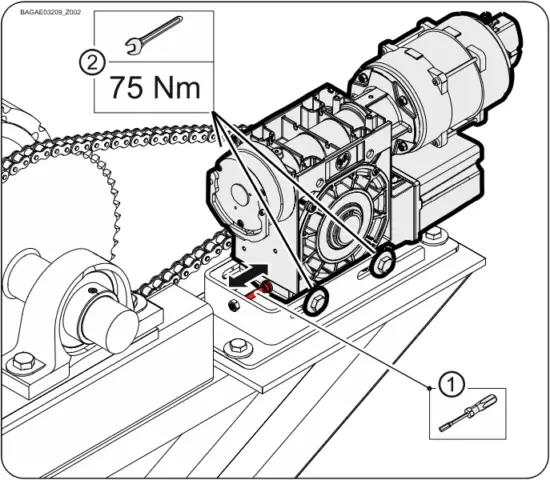
• Mount the drive unit. Tighten the connection elements to 75 Nm.
• Position the chain wheel (1) properly. Install the chain wheel (2). Secure the chain wheel (3).
• Tighten the chain wheel properly (1). Tighten all connection elements (M12) to 75 Nm (2). Install all other connection elements according to the specifications of the door manufacturer.
4 Electrical installation
![]() Warning – Danger to life from electric current!
Warning – Danger to life from electric current!
- Switch the mains OFF and check that the cables are de-energised
- Observe the applicable regulations and standards
- Make a proper electrical connection
- Use suitable tools
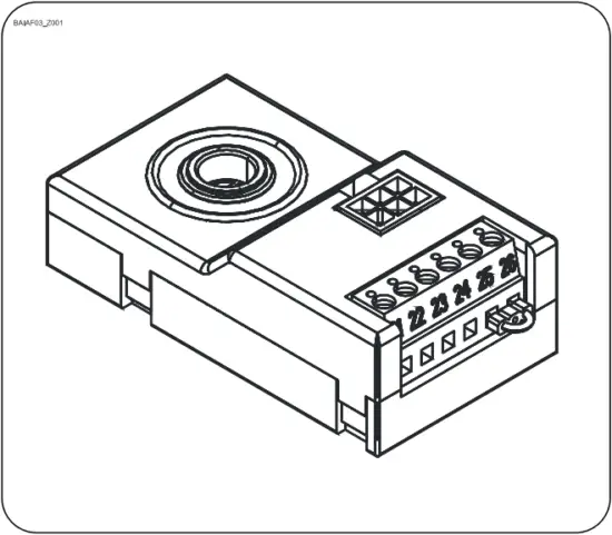
Performing electrical installation
| Remove the cover. | Insert the motor plug. | Insert the limit switch plug. |
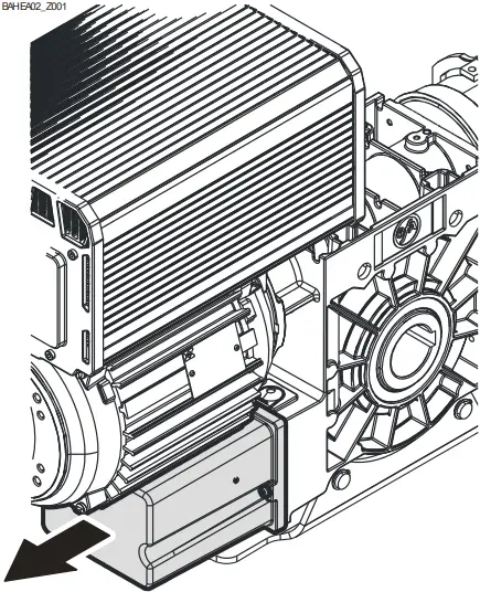 | 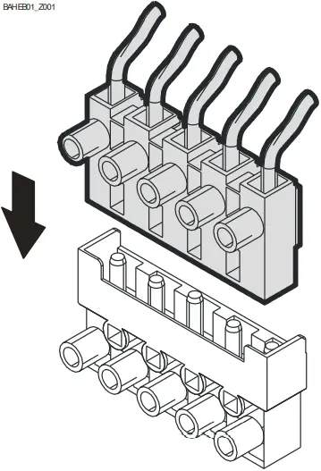 | 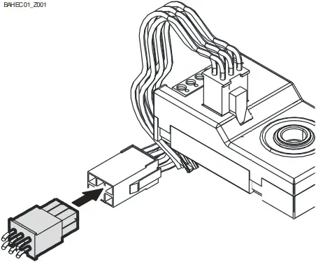 |
Completing the electrical installation
Mount the cable entries and/or cable glands.
5 Limit switch setting
The setting of the final limit positions OPEN and CLOSE is described in the instructions for the door control.
![]() The door control must meet Performance Level c!
The door control must meet Performance Level c!
Use only door controls that evaluate the limit switch according to EN 12543 and meet Performance Level c.
6 Motor connection
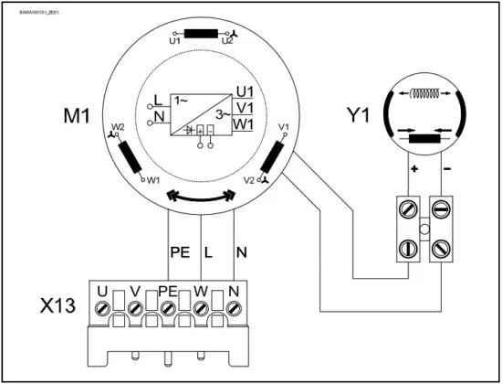
| M1 | Motor |
| X13 | Motor plug |
| Y1 | Spring applied brake |
7 Limit switch connection
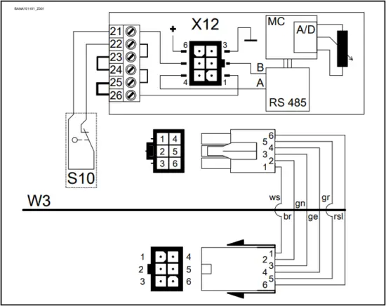
| S10 | Emergency manual operation |
| X12 | DES connection |
| 1 | Safety circuit |
| 2 | Channel B (RS485) |
| 3 | Ground |
| 4 | Channel A (RS485) |
| 5 | Safety circuit |
| 6 | Supply voltage |
| W3 | Connection cable freqency inverter (FI) |
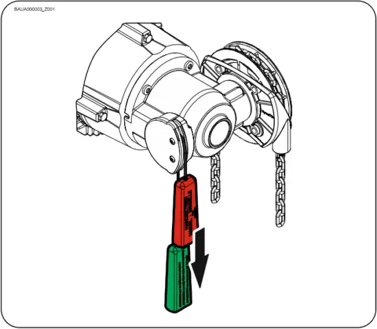
8 Emergency manual operation (hand chain operator)
Emergency manual operation is designed for opening or closing the door without power supply. Its activation interrupts the control voltage. Electrical operation is no longer possible.
![]() Warning - Injuries due to incorrect operation!
Warning - Injuries due to incorrect operation!
- Switch off voltage.
- Adopt a secure position.
- For drive units with brake, the emergency manual operation must be carried out against the closed brake.
![]() Warning – Danger of the door dropping!
Warning – Danger of the door dropping!
If you need to apply more than the permissible force of 390N (according to DIN EN 12604/DIN EN 12453) to move the door by emergency manual operation, this indicates a stalling on the drive unit or door. Releasing the stalling may cause the door to drop.
- Adopt a secure position.
- For drive units with brake, the emergency manual operation must be carried out against the closed brake.
![]() Caution - Damage to components!
Caution - Damage to components!
- Do not move the door beyond the final limit positions.
Switch on by pulling the red handle. Open or close by pulling the chain. Switch off by pulling the green handle.
9 Completing commissioning / inspection
Check the following components and then install all covers.
Gearbox
Check the drive unit for loss of oil (a few drops can be neglected). Protect the output-shaft permanently against corrosion.
Mounting
Check that all connection elements (consoles, torque mounts, screws, locking rings, etc.) are secure and in proper condition.
Electrical wiring
Check the connection cables and cabling for damage or crushing. Check that the screw connections and plug connections are fitted properly with a good electric contact.
Emergency manual operation
Check the function with the power disconnected. Perform the check only between the final limit positions.
Limit switch
Check the final limit positions by opening and closing fully. The safety area must not be approached.
Brake
![]() Warning – Potential injury or danger to life!
Warning – Potential injury or danger to life!
- Carry out a brake test. Overrun depends on the door and its equipment. The specifications of the door manufacturer must be observed.
- Brake lift may only be used in the final limit position CLOSE for doors that have no counter-balancing.
![]() Warning – Potential injury or danger to life!
Warning – Potential injury or danger to life!
Lifecycle brake – change complete brake unit at:
- Operation with mains supply after 250.000 cycles
- Operation with Inverter after 1.000.000 cycles
In an environment that can affect the coefficient of friction of the brake pad (atmosphere with oil, solvents, detergents, etc.), class of protection IP65i must be adopted.
Drive unit
![]() Note!
Note!
- Engage a qualified engineer to check the drive unit annually
- Apply shorter inspection intervals for doors that are operated frequently
- Observe the applicable regulations and standards
10 Disposal
Dispose of packaging
Dispose of the packaging material properly according to the local legal regulations or recycle it.
Dispose of old devices
Dispose of old devices properly according to local legal regulations. Return old devices to the return and collection systems available. You can also return GfA products free of charge. Please apply enough postage to the package and mark it as “old devices”.
![]() Notice- Environmental damage!
Notice- Environmental damage!
The gearbox contains oil.
- Ensure proper disposal according to local legal regulations.
![]() Declaration of incorporation
Declaration of incorporation
within the meaning of Machinery Directive 2006/42/EC for partly completed machinery, Appendix II Part B
Declaration of conformity
within the meaning of EMC Directive 2014/30/EU
within the meaning of RoHS Directive 2011/65/EU
We,
GfA ELEKTROMATEN GmbH & Co. KG
declare under our sole responsibility that the following product complies with the above directives and is only intended for installation in a door system.
Drive unit
KE 40.40 FU-40,00
Part no.: 10003840 10812
We undertake to transmit in response to a reasoned request by the appropriate regulatory authorities the special documents on the partly completed machinery.
This product must only be put into operation when it has been determined that the complete machine/system in which it has been installed complies with the provisions of the above mentioned directives.
Authorised representative to compile the technical documents is the undersigned.
Düsseldorf, 10.08.2018
Stephan Kleine
CEO
![]()
Signature
The following requirements from Appendix I of the Machinery Directive 2006/42/EC are met:
1.1.2, 1.1.3, 1.1.5, 1.2.2, 1.2.3, 1.2.6, 1.3.2, 1.3.3, 1.3.9, 1.5.1, 1.5.2, 1.5.4, 1.5.6, 1.5.7, 1.5.8, 1.5.9, 1.5.10, 1.5.11, 1.5.13, 1.6.1, 1.6.2, 1.6.4, 1.7.2, 1.7.3, 1.7.4.3.
Standards applied:
EN 12453:2001
Industrial, commercial and garage doors and gates – Safety in use of power operated doors Requirements
EN 12604:2017
Industrial, commercial and garage doors and gates – Mechanical aspects – Requirements
EN 60335-1:2012
Household and similar electrical appliances Safety – Part 1: General requirements
EN 61000-6-2:2005
Electromagnetic compatibility (EMC) Part 6-2 Generic standards Immunity standard for industrial environments
EN 61000-6-3:2007
Electromagnetic compatibility (EMC) Part 6-3 Generic standards Emission standard for residential, commercial and light-industrial environments


