
Nakamichi NHMD600.1 Class-D Mono Block Power Amplifier User Manual
INTRODUCTION
Thank you for your purchase of our Nakamichi product and we warmly welcome you to the Nakamichi family! Do keep your original invoice and purchase receipt in a safe place in case of future service and warranty claims. You may also contact your appointed Nakamichi service agent for any future technical support requirements.
ACCESSORY LIST
- User Manual 2pcs
- Amplifier 1pc
- Mounting Screw(@4x20mm) 4pcs
- Mounting Bracket 3crew(@4x6mm) 4pcs
- Remote Control 1 set
- Fixing frome (34x20mm) 1 pcs
- L-type wrench(L=90mm) 1pcs
SPECIFICATIONS
- N-power Output@4C: 400Wx1
- N-power Output@2C: 600Wx1
- Max Output Power: 3600W
- Full Frequency Response: 5Hz-20KHz
- SUB Frequency Response: 30-250Hz
- Dignal To Noise Ratio: +N 190dB
- Sensitivity: 0.32V-6.5V
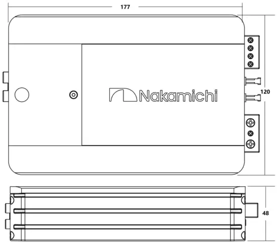
- Unit Dimensions(LxHxW): 195x120x48mm
- Net Weight Approx.: 1.3kp
- Box Dimensions(LxHxW): 265x218x75mm
- Gross Weight Approx: 2.4kp
All specifications subject to change without notice.
DIMENSIONS (UNIT:MM)
POWER CONNECTION LEADS
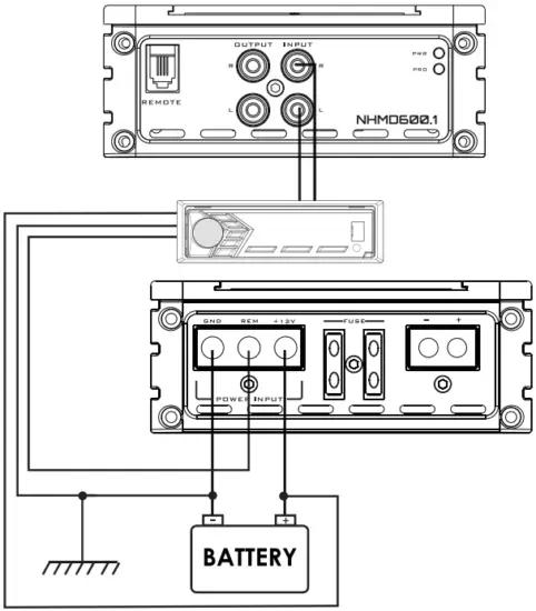
Notes on the power supply
Connect the +l2V power input lead only after all other leads have been connected. Be sure to connect the ground wire of the unit securely to a meatal part of the car. A lose connection may cause a malfunction of the amplifier.
REMOTE:
The unit is turned on by applying +12Volts to this terminal. This terminal does not draw heavy current like the two power terminal so a thinner connecting wire is acceptable. Standard 18 GAUGE is fine and the standard colour is yellow. If the radio is equipped with a power antenna control wire, it can drive this terminal. If the power antenna wire is already in use, you can still splice into it. With this method, the unit will turn on automatically with the radio.
Use the power supply lead with a fuse attached whose value is the same as original fuse. Place the fuse in power supply lead as close as possible to the car battery. During a full power operation, Maxlmum current will run through the system. Therefore. Make sure the that the leads to be connected to the +12V and GND terminals of the unit respectively must be larger than 8-Gauge(AWG.8).
CONNECTION 1: 1-SPEAKER MODE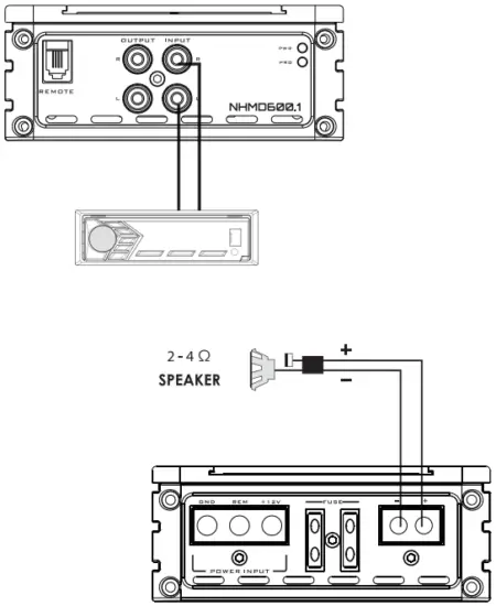
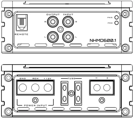
PANEL CONTROLS AND FEATURES
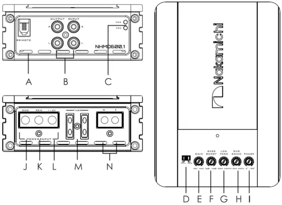
- A. REMOTE LEVEL CONTROL INPUT D E F G H I
Attached the included remote level control here to control the volume level to the subwoofer independently. - B. LOW LEVEL RCA INPUT
These RCA input jacks connect with your source unit RCA low level outputs or via optional adapter with your source unit speaker high level outputs. The use of high quality twisted pair car audio cables is recommended to reduce the possibility of audio signal demotion. - C. POWER AND PROTECTION INDICATOR
The protection red LED will light up , if there is a fault present in the amplifier. Please disconnect the amplifier and resolve the foult before reconnecting the amplifier. The power indicator green LED will light up when the amplifier is working correctly. - D. SPEAKER CROSSOVER CONTROL
Depending on the selected switch the amplifier will operate at full or sub mode. - E. SPEAKER GAIN CONTROL
The gain control will match the amplifiers sensitivity to the source signal voltage. - F. BASs BOOST
The BASS BOOST feature will increase the sound level in the bass frequencies. - G. SPEAKER LOW PA3S CROSSOVER FREQUENCY
Controls low frequency of the amplifier between 30Hz to 250Hz. - H. SUBSONIC FILTER CONTROL
This control allows you to filter out unwanted low frequencies from 15Hz to 60Hz, this allows you to increase the power handing of your installed woofers. - I. PHASE
Controls phase of the amplifier between 0°to 180°. - J. GND(-) = GROUND CONNECTION
Connect this cable directly to the metal frame of the vehicle, ensuring that the metal frame has been stripped of all paint down to the bare metal. Use the shortest distance possible. It is always a good idea to replace the vehicle battery ground terminal or any other factory ground points. - K. REM(ON/OFF) REMOTE CONTROL
When using low level inputs, the amplifier REM-IN should be connected to the REM-OUT of the source unit. The source unit will control the amplifier to automatically turn on or off. - L. +12V = POWER SUPPLY
Connect this terminal through a fuse or circuit beraker to the positive terminal of the vehicle battery or the positive terminal of an isolated audio system battery.
M. FUSE
Do not use a fuse with a different value and NEVER replace the fuse with a wire or coin. - N. SPEAKER CONNECTIONS
Connect your speakers and woofers to there terminals, ensuring proper polarity during connection. Never connect the speaker cables to the chassis ground.
INTERFERENCE
All cables can create interference. The power cable and cinch / RCA audio cables are very prone to interference from other sources, while remote cables are less prone. Interference is often caused by the generator, ignition, or any other electronic parts or systems. Most of these problems can be eliminated by correct and careful wiring during setup. Here are some guidelines to follow.
- Use only a shielded audio cable for the wiring between the low level input of the amplifier and the RCA or DIN output of the radio.
- Lay the signal, speaker and power cables separately with enough distance from one another and also from each other car cable. Ir not possible, you can lay the circuit and ground cable together with the serial cables. Audio and speaker cable should be as far away from these as possible. The REM cable to the automatic antenna output of the radio can be laid together with the signal cables.
- Avoid ground loops by laying the ground wiring of all components towards a central point in a star layout. You can locate fne best point by measuring the voltage directly at the battery, and comparing the voltage value with the chosen ground point and the positive terminal of the amplifier. If the measured voltage is only slightly different, you’ve found the correct central location. Other wise please look for another point. You should measure with the ignition point for earth switched on.
- If there are pickups from external electrical sources into the speaker cables, divide the core leads and twist them together.
- If there are noises from the cor electrics, add on interference suppression choke into the power wiring.
- If there are humming noises, use thicker ground cables or add further ground cables to the chassis.
- To reduce contact resistance and bad and loose contacts, please solder the cable ends or use multi core cable ends, spade terminals or others. Gold Plated spade terminal are free of corrosion and hove the lowest contact resistance.
- Should all these measures not bring about any success, the use of a ground loop isolator may solve the problem.
TROUBLESHOOTING
If you experience operation or performance problems with this product, compare your installation with the electrical wiring diagram on the previous pages.If problems persist, read the following troubleshooting tips which may help eliminate the problems.
| NO OUTPUT | Low or no remote turn-on input | Check remote turn-on voltage output at amplifier and correct as needed |
| Fuse blown | Check power wire integrity and reversed polarity, repair as needed and replace fuse | |
| Power wires not connected | Check power wire and pound connections and repair of replace as needed | |
| Audio input not connected or no output from source | Check input connections and signal integrity, repair or replace as needed | |
| Speaker wires not connected | Check speaker wires and repair or replace as needed | |
| AUDIO CYCLES ON AND OFF | Speaker are blown | Check system with known working speaker and repair or replace speaker as needed |
| Thermal protection engages when amplifier heat sink temperature exceeds 75°C | Make sure there is proper ventilation for amplifier and improve ventilation as needed | |
| Loose or poor audio input | Check input connections and repair or replace as needed | |
| DISTORTED OUTPUT | Amplifier lecel sensitivity set too high: exceeding maximum output capability of amplifier | Reset gain referring to the turning section of the manual for detailed instructions |
| Impedance load to amplifier too low | Check speaker impedance load. if below 2C stereo or 4U mono rewire speakers to achieve a higher impedance | |
| Shorted speaker wires | Check speaker wire connections and repair or replace as needed | |
| Speaker not connected to amplifier properly | Check speaker wiring and repair of replace as needed refer to the installation section of this manual for detailed instructions | |
| Internal crossover not set properly for speaker | Reset crossovers referring to the multi-cross crossover configuration section of this manual | |
| DISTORTED OUTPUT (CONT’Dj | Speaker are blown | Check system with known working speaker and repair or replace as needed |
| POOR BASS RESPONSE | Speaker wired wrong polarity causing cancellation at low frequencies | Check speaker polarity and repair as needed Reset crossovers referring to the multi-cross |
| Crossover set incorrectly | Crossover configuration secrion of this manual for detailed instructions | |
| DISTORTED OUTPUT (CONT’D) | Impedance load to amplifier too low | Check speaker impedance load, if below 2C stereo or 4 ! mono rewire speaker to achieve a higher impedance |
| Short in power wire or incorrect power connections | Check power and ground connections and repair as needed | |
| Fuse used is smaller than recommended | Replace with proper fuse size | |
| Too much current being drawn | Check speaker impedance load, if below 2U stereo or 4 ‘ mono rewire speaker to achieve a higher impedance | |
| Short in power wire of incorrect | Check power and ground connections and repair as needed |
Customer Support
SCAN OUR QR CODE OR VISIT WWW.NAKAMICHICARAUDIO.COM FOR COMPLETE AUDIO SETTINGS INSTRUCTIONS![]() nakamichi.global
nakamichi.global![]() nakamichi.caraudio
nakamichi.caraudio
Made in China