SamYoung CM105(VHF)DMR Data Voice MODEM
Revision History
| Revision | Date | Author | Status/Comments |
| 1.0 | Feb.12.2020 | HI Lee | Initial Release |
Important
This user manual contains important information for operating instructions. Please read this manual carefully and completely before using the CM105 Radio modem. For additional information on 2-way radio, visit the following websites :
Copyright Information
The AMBE+2™ voice coding Technology embodied in this product is protected by intellectual property rights including patent rights, copyrights, and trade secrets of Digital Voice Systems, Inc. This voice coding Technology is licensed solely for use within this Communications Equipment. The user of this Technology is explicitly prohibited from attempting to extract, remove, decompile, reverse engineer, or disassemble the object code, or in any other way convert the Object Code into a human-readable form. US Patent Nos. #8,595,002 B2, #8,359,197, #8,200,497, #6,912,495 B2, #6,199,037 B1, #5,826,222, #5,754,974, #5,701,390, and #5,715,365.
Declaration of Conformity
EU Regulatory Conformance
This product is compliant with the essential requirements and other relevant provisions of the Directive 2014/53/EU. This product has been constructed so that it can operate in at least one member state i.e. the United Kingdom, or Italy. There are no restrictions on use. This product is also compliant with directive 2011/65/EU having been designed and manufactured to the ROHS requirements.
CE RF Exposure Requirements
Evaluation of EMF Exposure is completed using the power density equation defined in EN 62311 Annex A. For detail, please refer to our MPE report.
Federal Communication Commission (FCC) Regulations
This module is intended for OEM integrators. The OEM integrator is still responsible for the FCC compliance requirement of the end product, which integrates this module. Any changes or modifications not expressly approved by the manufacturer could void the user’s authority to operate this equipment. The OEM/integrator must test the final product to comply with unintentional before declaring compliance of their final product to Part 15 of the FCC Rules.m The CM105 has been certified for mobile and base radio applications. If the CM105 will be used for portable applications, the device must undergo SAR testing. Separate approval is required for all other operating configurations, including portable configuration with respect to FCC 47 CFR 2.1093 and different antenna configurations. It is the responsibility of the OEM to gain type approval for the host product. The CM105 does not require any further shielding and therefore can be fitted into any host product. The end-users of the product must be provided with transmitter/antenna installation requirements and operating conditions to satisfy RF exposure compliance by the integrator. The RF output is via a 50Ω SMA(RP-SMA female) connector. The final end product must be labeled in a visible area with the following ” Contains FCC ID: 2AJRJ-CM105 “. This transceiver works on frequencies that are not generally permitted. For frequency allocation, apply for a license at your local spectrum management authority. For actual usage contact your dealer or sales shop in order to get your transceiver adjusted to the al-located frequency range.
Important Notice for North American Users Regarding 406 MHz Guard Band
Frequency band 406 – 406.1 MHz is reserved for use ONLY as a distress beacon by the US Coast Guard and NOAA. Under no circumstance should this frequency band be part of the preprogrammed operating frequencies of this radio.
FCC RF Exposure Requirements
The external ¼ wave dipole antenna used with this module must be installed to provide a separation distance of at least 61 cm from all persons, and must not transmit simultaneously with any other antenna or transmitter, except in accordance with FCC multi-transmitter product procedures. Antenna gain must not exceed 2.15 dBi(DMR)
The antenna must be installed complying with the requirements of the manufacturer or supplier.
Antenna List:
- HW-146H-NPX100 : Helical antenna, Max -3.933 dBi
- HW-153H-NPX100 : Helical antenna, Max 2.15 dBi
- HW-170H-NPX100: Helical antenna, Max 2.15 dBi
Introduction
Overview
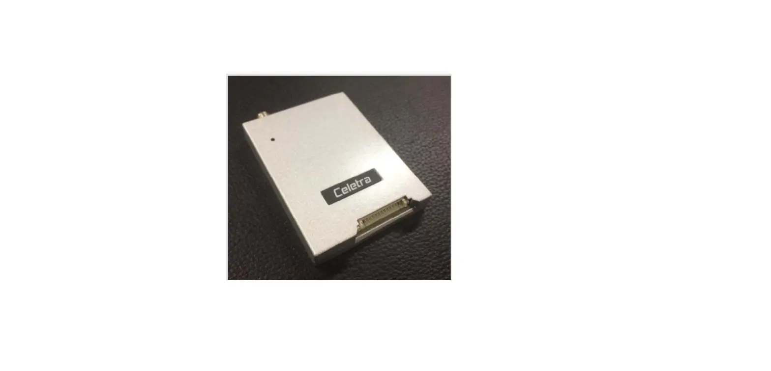
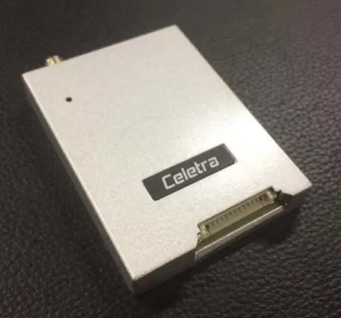
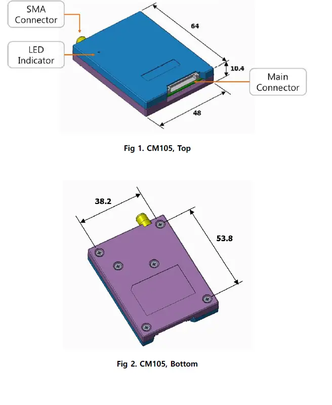
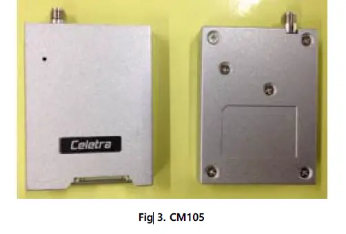
The CM405 MODEM is designed for DMR Data/Voice communication purposes. It supports the DMR Tier I, II protocol of ETSI Standard (ETSI TS 102 361). The CM105 MODEM is composed of aluminum die-cast housing with LED for status indicator, SMA RF connector, and the main connector for Data communication service.
Features
- Serial Communication Interface (UART 3.3V Logic Level)
- Operation status LED indicator (Power/CD/TX/RX)
- 5 Watts Output Power.
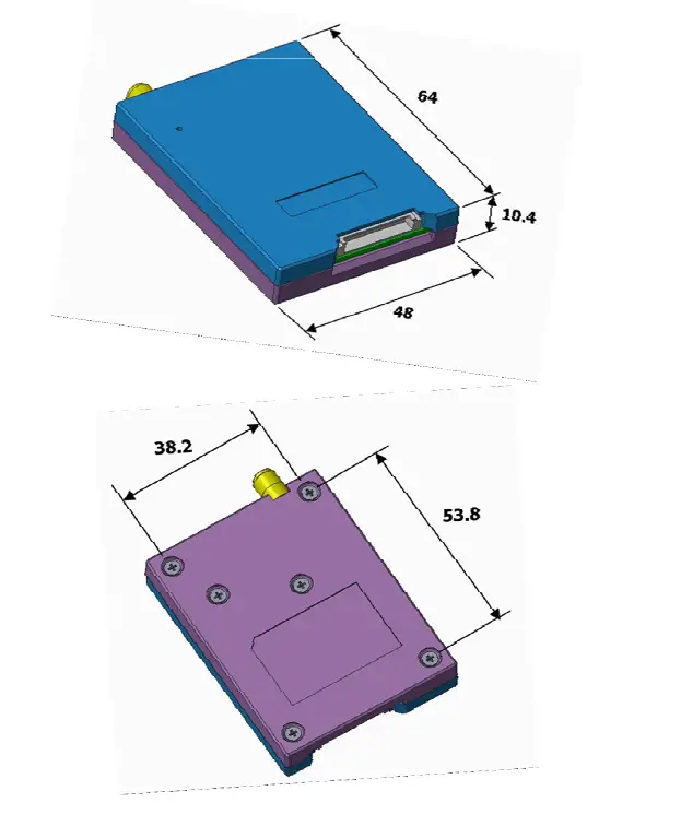
Table1. Mechanical Dimensions (Unit: mm)
| Parameter | Value |
| Length (mm) | 64 |
| Width (mm) | 48 |
| Thickness (mm) | 10.4 |
| Weight (g) | 50 |
Interface Description
- Power In ( 7.4V, 2000mA )
- Indication LED
- Red, Green LED
- UART, 3wire (Tx, Rx, Gnd) interface
Signal Level: 3.3V
| Parameter | Value |
| Speed (Baud rate) | 38400 [bps] |
| Data bits | 8 |
| Parity bit | None |
| Stop bit | 1 |
RF Interface
- VHF:136 ~ 174 MHz, 5W RF Output power (CM105)
- Compliant ETSI TS 102-361 / ETSI TS 102-490 / ETSI TS 102-658
- RF Connector type: RP-SMA female Connector (FCC)
- SMA female Connector or RP-SMA female Connector (CE)
Pin Description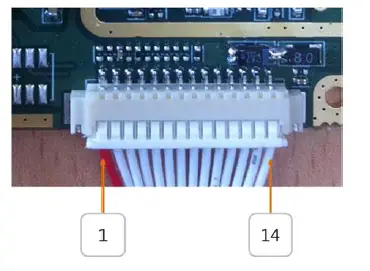
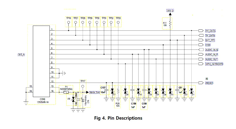
| Pin Number | Name | Signal Level | Note | |
| 1 | Rx_Data | 3.3V | UART (Signal Level: 3.3V) | |
| 2 | Tx_Data | 3.3V | UART (Signal Level: 3.3V) | |
| 3 | Ext_PTT | 3.3V | Digital Input (Low Active) |
| 4 | COR | 3.3V | Digital Out (High Active) |
| 5 | Audio_In_N | 10mV (nominal) | Analog In (Mic_N) |
| 6 | Audio_In_P | 10mV (nominal) | Analog In (Mic_P) |
| 7 | Audio_Out | 1V (peak) | Analog Out |
| 8 | Boot 0 | GPIO_In (for upgrade F/W) | |
| 9 | GND | ||
| 10 | GND | ||
| 11 | GND | ||
| 12 | /Reset | Digital Input (Low Active) | |
| 13 | Vcc (7.4V) | 7.4V±5% | |
| 14 | Vcc (7.4V) | 7.4V±5% |
Antenna Connector
RF Connector type: RP-SMA Connector (female) or SMA Connector (female)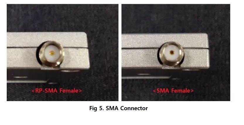
Specifications
General Specifications
| General | Description | Remark |
| Frequency Range | UHF: 136~174 MHz | |
| Channel Capacity | 512 | Opt. 1024CH |
| Channel Spacing | 12.5 kHz | |
| Operating Voltage | DC 7.4V±5%, 2,000mA | |
| Frequency Stability | 1.5 ppm | |
| Antenna Impedance | 50 Ω | |
| Digital VOCODER | AMBE+2 | |
| Receiver | ||
| Analog Sensitivity | -121 dBm | |
| Digital Sensitivity | -117 dBm (1% BER) | |
| Intermodulation | > 65 dB | |
| Adjacent Channel Selectivity | > 60 dB | |
| Spurious Rejection | > 70 dB | |
| Blocking | > 84 dB | |
| Hum and Noise | – 40 dB | |
| Audio Impedance | 16 ohm | |
| Audio output | Typ. 7mW | |
| Audio Response | +1/-3 dB | |
| Conducted Spurious Emission | < -57dBm | |
| Transmitter | ||
| RF Output Power | 5W/1W (± 1.5 dB) | High/Low Power |
| Modulation Limiting | ± 2.5 kHz | |
| FM Hum and Noise | – 40 dB | |
| Conducted/Radiated Emission | < -36 dBm | |
| Adjacent Channel Power | < -60 dBc | |
| Frequency Error | ± 1.5 ppm | |
| Audio Distortion | 3% | |
| Reliability | ||
| Operating Temperature | -30°C ~ 60°C | |
| Storage Temperature | -40°C ~ 85°C | |
| ESD | IEC61000-4-2 Level 3 | |
LED Indication
| Item | Description | Remark |
| POWER | Lit up at Power ON (Red and Green) | |
| CD | Indicate carrier detection (Green) | |
| Tx | Indicate transmit status (Red) | |
| Rx | Indicate receive status (Green) |
Internal Flash Memory (Option)
CM405 MODEM includes internal flash memory for voice recording. The capacity of the flash memory is 64Mbit(Optional). The maximum recording time is about 4.5hours. Users can control the voice recording and play via AT commands. For more detailed information on AT command list document.
AT Commands
CM405 MODEM is controlled by Celetra’s AT command, refer to AT command list in the AT_Command_List_DMR_V19_20180827.pdf document.
MODEM Test Tool
Celetra provides a simple MODEM test tool “CeletraRadioTester.exe” for evaluating and guiding the AT command usage. It is not necessary to install but just executes it. User can use normal UART hyper terminal also (Ex: Tera term, Putty …).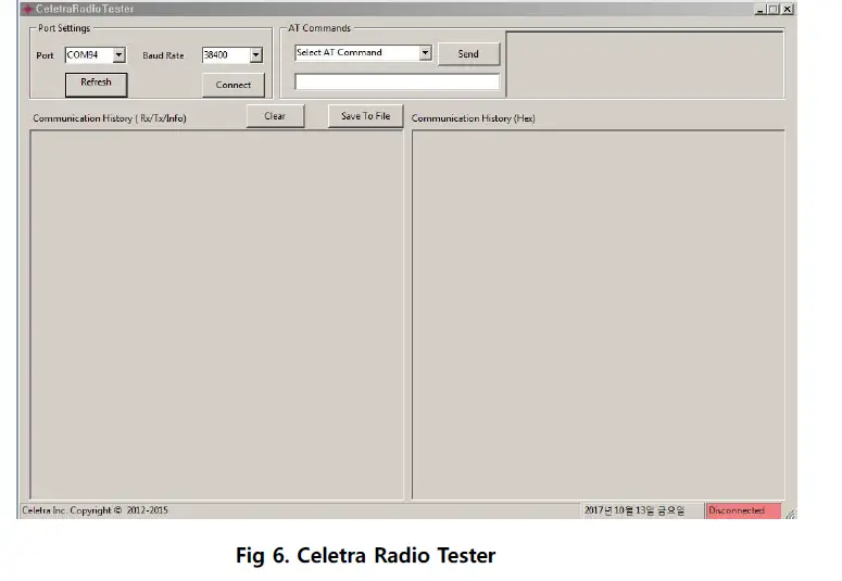
Set Connection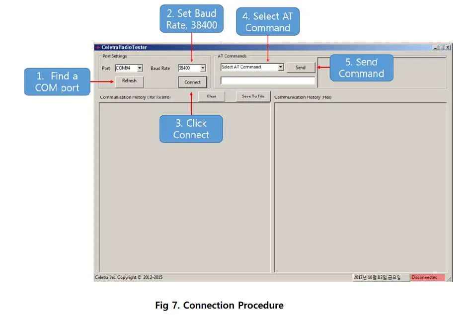
Successfully connected to the MODEM, the Status indication changed to “Connected”. Users can select the AT Command and send it to the MODEM. The right side of the window displays the related command explanation and usage.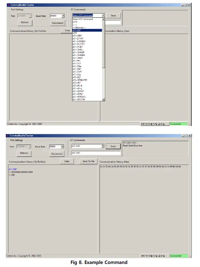
Connector (14 Pin Main Connector)
Connector: 12505WR-14, Yeonho Electronics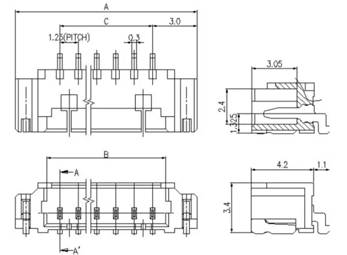
Housing: 12505HS-14, Terminal: 12505TS, Yeonho Electronics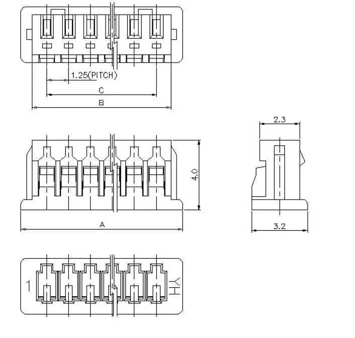
Mechanic Dimension
Unit: mm