![]()
Redline Cyc Laser Defense System
Owner’s Manual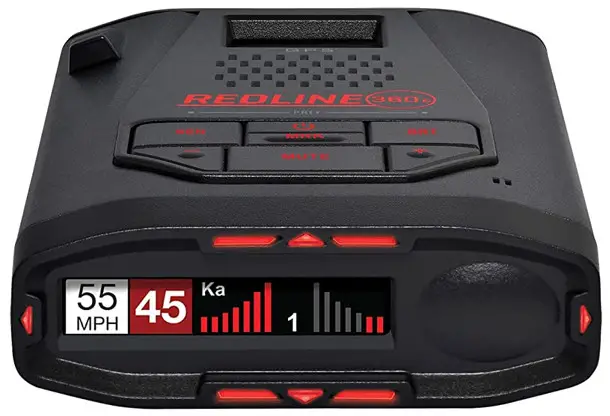
REDLINE Cis SYSTEMS
Owners Manual
THE DRIVING SPIRIT, AWAKENED Game-Changing Performance. Unmatched Intelligence.
 Introduction
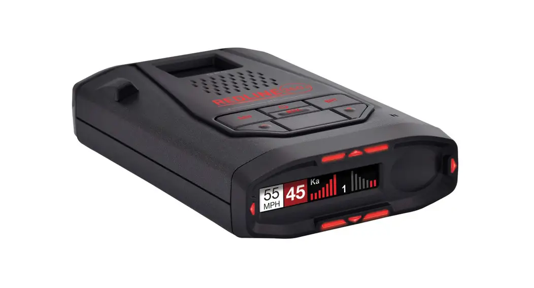
Your new ESCORT Redline Ci-c is the most advanced custom-installed radar and laser defense system ever designed.
The ESCORT Redline Ci-c includes multiple LNA (low noise amplifier) receivers using Ultra DSP (digital signal processing) for superior radar detection range and false alert filtering while reporting threat direction information. The included Laser Shifter VX shifters deliver the ultimate defense against all LIDAR laser guns, including new variable pulse rate guns. Also included is a full color OLED display and all the performance and features that only ESCORT can deliver.
Redline Ci-c FEATURES
- Updatable IVT Filter automatically reduces false alerts from moving In-Vehicle Technology systems and adaptive cruise control
- GPS location-based intelligence automatically locks out false alerts and allows you to mark locations for future reference
- Exclusive Total Shield™ Technology makes the ESCORT Redline Ci-c totally undetectable by any radar detector detector (RDD)
- Access to ESCORT’s DEFENDER Database, which warns you of verified speed traps, speed cameras and red light cameras
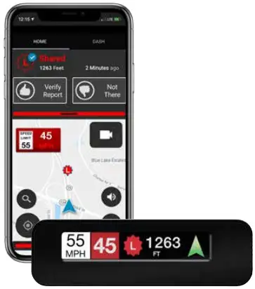
- Built-In Bluetooth technology gives you access to ESCORT’s award-winning real-time ticket protection app, Drive Smarter®!
- Dual-Band Wi-Fi – Connecting to a Wi-Fi hotspot allows for easy software updates and direct access to Driver Smarter ® ’s community-based alerts and speed limit data.
IMPORTANT NOTES
Warning
Never, under any circumstances, look at the Laser Shifter VX sensors while they are powered on and operating. Do not view with optical instruments (like magnifiers).
CLASS 1 LASER PRODUCT
This product complies with IEC 60825-1:2007-03 Ed. 2.0
This product complies with 21CFR Subchapter J Parts 1040.10 and 1040.11 except for deviations pursuant to Laser Notice No. 50 dated June 24, 2007.
Please Note: This product may be limited or prohibited in some jurisdictions. Check applicable laws before using.
FCC Note: Modifications not expressly approved by the manufacturer could void the user’s FCC granted authority to operate the equipment.
PRODUCT SERVICE AND SUPPORT
For any questions about operating or installing this new Escort product, PLEASE CONTACT ESCORT FIRST…do not return this product to the retail store. The contact information for Escort will vary depending on the country in which you purchased and utilize the product. For the latest contact information, please go to www.escortradar.com/support
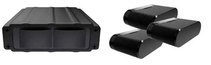
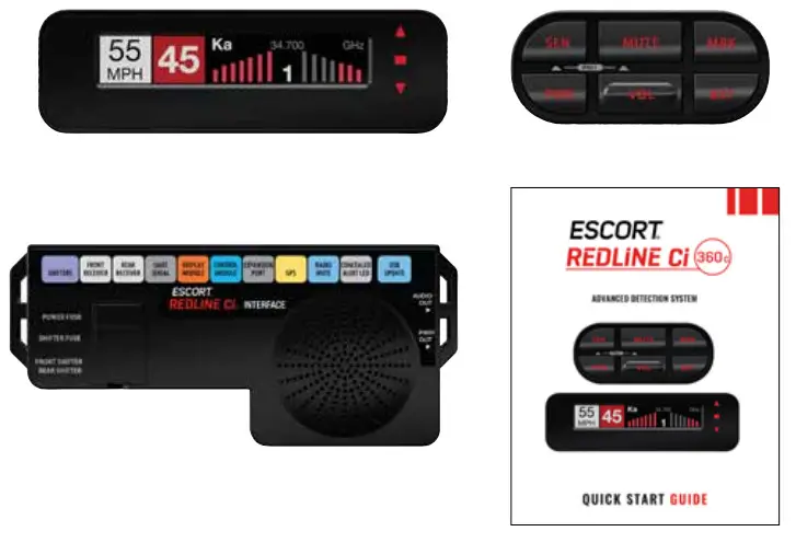
WHAT’S IN THE BOX
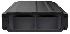
- Receiver
(Redline Ci 360c includes 2) - 3 Shifter VX transceivers, 2 Shifter VX transmitters (Redline Ci 360c only)

- Bridge Box (Redline Ci 360c only)
- GPS Antenna
- Display Module
- Control Module
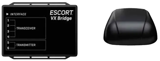
- Interface
- Quick Start Guide

Not shown:
Concealed Alert Indicator Radio Mute Cable Download Data Cable
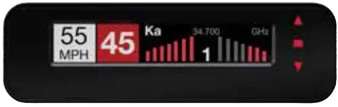
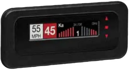
DISPLAY AND MENU – Redline Ci 360c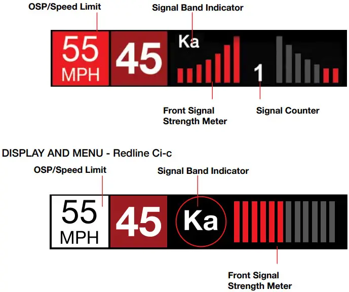
- Signal Band Indicator
Displays the radar band of the alert:
– X Band (commonly false alerts).
– K band (used by police radar and false alerts)
– Ka band (almost always police radar)
– Laser (almost always police) - Signal Strength Meters
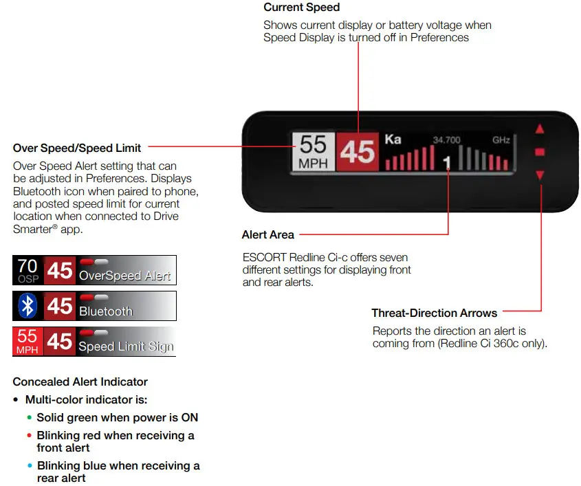
Displays the signal strength, or how close, the alert is. The more alert bars displayed, the stronger the signal strength. The left meter is front signal strength. The right meter is rear signal strength (Redline Ci 360c only). - OSP/Speed Limit Indicator
Over Speed alert setting, can be adjusted in the Programming menu. Bluetooth icon will appear here when paired to phone. Speed limit data will appear here when connected to the Drive Smarter app or your mobile Wi-Fi spot. - Signal Counter
Displays the number of alerts being detected. - Speed
Displays the current speed. When Speed
Display is off, displays the vehicle voltage.
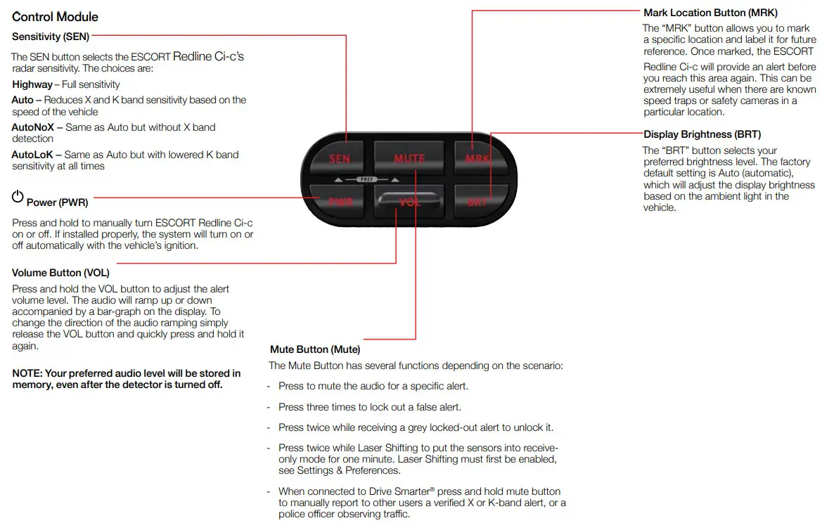
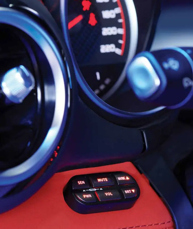
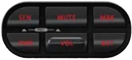
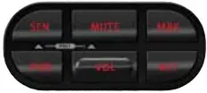
Control Module
REGISTRATION
Follow these steps to register your ESCORT Redline Ci-c or Redline Ci 360c. You will need the detector’s serial number to complete the registration. To view the serial number, hold down the MRK and SEN buttons while powering on the detector.
- Visit www.EscortRadar.com and click Product Registration.
- Click the “Registration for all devices” link.
- Follow the onscreen instructions to register your device.
Be sure to write down the username and password you create, as you will need this information to access the Drive Smarter ® ticket protection app. (You will also receive an e-mail with this information, once you have registered your device.)
DOWNLOAD AND CONNECT TO DRIVE SMARTER®
- Power on Redline Ci-c.
- Install and run the Drive Smarter®app on your smartphone.
- In the Drive Smarter® app, press the Account button then select “Add Detector”.
- Follow the prompts in the Drive Smarter® app to connect Redline Ci-c and your mobile Wi-Fi hotspot.
Note: the first time you run the app, you will be prompted to register a new account.
![]()

 Installation
REDLINE Ci-c & Ci 360c COMPONENTS
Front Radar Receiver
- Weatherproof radar receiver
- Two universal mounting brackets with stainless steel hardware
- Built-in 3-foot cable with waterproof connector
- 13-foot cable with waterproof connector and inline grommet

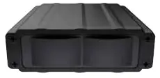
Rear Radar Receiver (Optional for Redline Ci-c)
- Weatherproof radar receiver
- Two universal mounting brackets with stainless steel hardware
- Built-in 3-foot cable with waterproof connector
- 13-foot cable with waterproof connector and inline grommet
- 12-foot extension cable with waterproof connectors

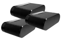
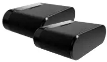
Front Laser Shifter VX Sensors (Optional for Redline Ci-c)
- 2 transceivers and 1 transmitter
- 6-foot cables with waterproof connectors
- Mounting hardware and bubble level
Rear Laser Shifter VX Sensors (Optional for Redline Ci-c)
- 2 transceivers and 1 transmitter
- 6-foot cables with waterproof connectors
- 2 x 20-foot extension cables
- Mounting hardware and bubble level
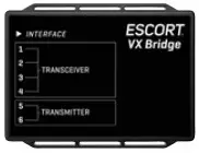
Shifter VX Bridge Box (Optional for Redline Ci-c)
- Weatherproof Bridge Box is used to connect Shifter VX Sensors to main interface
GPS Antenna
- Weatherproof magnetically mounted GPS Antenna
- 30-foot cable with modular connector
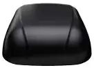
Display Module
- Display mounts easily to instrument pod, dashboard, or console
- Two bezels provided for optional in-dash mounting
- Adhesive pads provided for secure mounting
Control Module
- Controller mounts easily to instrument pod, dashboard, or console
- Adhesive pads provided for secure mounting
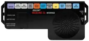
Interface
- Central module connects to switched 12-volt power and ground
- All components plug directly in using modular connections

Documentation
- Quick Start Guide
Not Shown:
In-dash Display Bezels
- For a factory-installed look, use either the black or platinum in-dash bezel for easy mounting to instrument pod, dashboard, or console
- Integrated adhesive backing for secure mounting
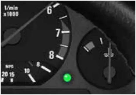
Concealed Alert Indicator
- Multi-color indicator is:
- Solid green when power is ON
- Blinking red when receiving a front alert
- Blinking blue when receiving a rear alert (ESCORT Redline Ci-c only)
- Blinking blue when system is undergoing a firmware update
- 6-foot cable with modular connector
- Bezel provided mounts easily to instrument pod, dashboard, or console
Radio Mute Cable
- 6-foot cable connects to compatible vehicle audio systems and automatically mutes the audio during alerts
Download Data Cable
- Provides access to update data via the Internet
Built-in Diagnostics
- Confirms all components are operational
INSTALLATION SCHEMATIC OVERVIEW
Letter References For Components (Color Coded Connections To Interface)
A Interface
B Front Radar Receiver (White Stripe)
C 3 Front Shifter VX Sensors (Purple, optional, included with ESCORT Redline Ci 360c plug into ports 1, 2 & 5 on Shifter VX Bridge Box)
D Shifter VX Bridge Box (optional, included with ESCORT Redline Ci 360c plugs into Interface using supplied cable with no stripe or shrink)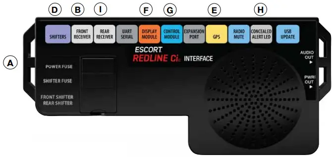 E GPS Antenna (Yellow Shrink)
F Display Module (Orange Shrink)
G Control Module (Blue Shrink)
H Concealed Alert Indicator (Gray Shrink)
I Rear Radar Receiver (Gray Shrink, optional, included with ESCORT Redline Ci 360c)
J Rear Shifter VX Sensors (optional, included with ESCORT Redline Ci 360c)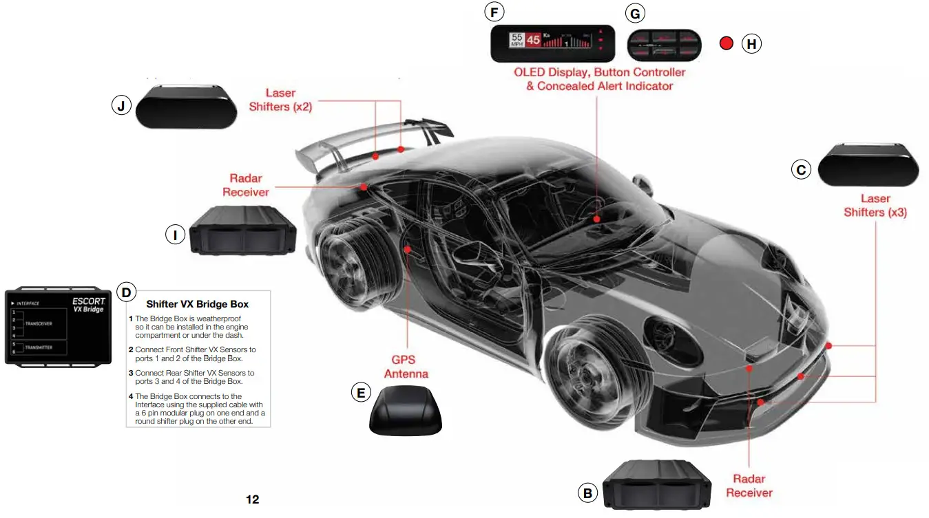
IMPORTANT NOTES
Installation Warnings
- It is recommended that you have a professional install your new ESCORT Redline Ci-c. Installation of this system requires experience and expertise in automotive electronics. If you are unfamiliar with automotive electronics, car audio specialists and many car dealers can install your ESCORT Redline Ci-c for you.
- Attempting to install this product without expertise in automotive electronics installation can cause personal injury or damage to your vehicle.
- If your vehicle is damaged during installation its safety systems may be compromised, which could cause personal injury or property damage.
- Improper installation may void ESCORT Redline Ci-c’s warranty.
Performance Warning
To get the best performance possible, the mounting location of the radar receiver is critical. Although radar signals will pass through some types of plastic, mounting the radar receiver so that it has a clear “view” of the road will ensure maximum warning.
Since Laser signals will not pass through objects, including most plastics, it is critical that the Laser Shifters are mounted perfectly level and have an unobstructed “view” of the road.
Read This First
Please read these instructions in their entirety before starting your installation.
For the easiest, trouble-free installation, install the interface first and wire it to a 12-volt switched circuit. Then, before installing the other components, plug all of them into the interface and power up the unit to confirm proper operation.
Error Codes
Below is a list of error codes which are shown in error messages. The codes help diagnose the cause of the error.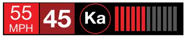
Error
| Replace | A critical issue has been reported requiring component to be replaced or repaired. |
| Check | Connections and wiring of component should be checked. If problem persists there may be an issue with component. |
| High Temp | Component is too hot. Mounting it in a cooler location may be necessary. |
| Hi Volt | Power supply voltage is too high. Voltage must be between 10.5–16 V DC. |
| Lo Volt | Power supply voltage is too low. Voltage must be between 10.5–16 V DC. |
Component
| IF | Interface |
| FR | Front Radar Receiver |
| RR | Rear Radar Receiver |
| GR | GPS Receiver |
| SB | Shifter Bridge Box |
| S1 | Shifter Sensor 1 |
| S2 | Shifter Sensor 2 |
| S3 | Shifter Sensor 3 |
| S4 | Shifter Sensor 4 |
| S5 | Shifter Sensor 5 |
| S6 | Shifter Sensor 6 |
For information about accessing the error code log, visit the “User Manuals” section of the escort radar. com website.
INSTALLATION INSTRUCTIONS
Installation Tips
While following the steps throughout this manual, please refer to the following recommendations for a professional, trouble-free installation:
- Determine the best location for the radar receiver. The best location is typically under the bumper, or inside the front grill of the vehicle. For the best radar performance, install the radar receiver horizontally, with a clear “view” of the road.
- Entry points into the interior may be located behind the plastic liner in the wheel well, fuse box, or unused grommets.
- There are often many existing entry points at the rear of the vehicle as well:
• Gaskets behind license plates, around illumination lamps, and near trunk lid hinges.
• Tail light wiring gaskets are often easily accessible and large enough to add cables. - If there are no suitable openings, it will be necessary to drill a hole through the firewall:
a. Thoroughly investigate all locations before drilling any holes! Ensure no wires, hoses, or other vehicle components will be damaged.
b. On vehicles with automatic transmissions, there is often a location for mounting a clutch pedal. This location is typically an ideal location to drill.
c. Before drilling, cover the surface being drilled with masking tape to prevent damage to the anti-corrosion coating in the event the drill bit slips.
d. Drill a 13/32″ or 7/16″ hole. - When pulling the inline grommet to the entry point, apply rubbing alcohol to a section of the cable to reduce friction and quickly pull the grommet along the length.
- The cables of units mounted at the rear of the vehicle can generally be routed through the trunk compartment and concealed under trim panels quite easily. If necessary, the cables can also be routed under the vehicle and through an opening in the firewall. Be sure to secure cables away from moving parts and hot surfaces.
- A quality crimper for modular connectors can be used to cut cables to length and replace the connector. Removing the connectors may also make it easier to enter the vehicle’s interior through existing openings.
NOTE:
• Only an exact replacement for the standard connector can be used. Do not attempt to cut the wires unless the proper connector and crimping tools are available.
• Connectors cannot be reused.
• Do not cut the cable too short! Provide enough cable to route to the Interface and add a couple extra feet to ease installation
• Install the new connector such that its locking tab is on the same side as the color coded stripe on the cable.
• Do not attempt to cut the cable and splice the wires together. - When drilling or cutting interior trim panels (for instance, when installing the Concealed Installation Alert Indicator or the optional Display Bezel), first cover the surface of the panel with masking tape to prevent accidental scratches.
Interface
- Install the Interface under the dash using zip-ties (not included).
NOTE: Do not mount Interface inside vehicle’s engine compartment! - Connect black wire (-) to ground, and restriped wire (+) to a switched 12-volt supply. (If ESCORT Redline Ci-c is left in the “on” position, it will automatically power on and off with the ignition).
- Front Radar Receiver, Shifter VX Bridge Box, Display and Control Modules, GPS Antenna, Concealed Alert LED, Radio Mute Cable, and optional Rear Radar Receiver* all plug into the Interface.
- It is recommended that after the Interface is installed and connected to power, all other components are plugged in and tested for proper operation before completing the installation.
IMPORTANT! When using optional Shifter VX sensors* ensure DIP switches 3 and 4 are moved down to the REAR SHIFTER position.
See the Interface illustration on page 13.
* Included with ESCORT Redline Ci 360c
Front Radar Receiver White Stripe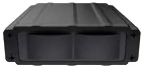
- Determine the best location for the Radar Receiver. The best location is typically under the bumper or inside the front grille of the vehicle. For the best radar performance install the Radar Receiver flat, horizontally, not on its side.
- The included adjustable mounting clamps can be used to easily secure the Radar Receiver to the slats in a grille or the edge of an opening.
• To tighten clamp jaws, insert a 9/64” hex key into the screw on the front of each clamp and turn clockwise.
• To adjust the angle and remove the clamps, use the screw on the side of each clamp. - Alternatively, you can use the supplied U-shaped and right-angle mounting brackets. Mark the mounting location and drill pilot holes in the vehicle if necessary. It is recommended that the Radar Receiver is secured to the brackets first, and then mount the Receiver and brackets assembly to the vehicle.
- Slide the heats rink onto the Radar Receiver cable then plug into the harness and route the cable toward the interior of the vehicle. Shrink the heats rink onto the inline connector and secure the cable with zip-ties. Although waterproof, it is best to locate the inline connector in a dry area protected from moving parts, road debris, and hot surfaces such as the radiator and radiator hoses.
- Find a suitable entry point into the vehicle’s interior. Refer to the Installation Tips section.
- Feed the harness into the vehicle’s interior and to the Interface. Plug into the connector labeled “Front Receiver.”
- If entering through a drilled hole, pull the grommet on the harness until the end sticks through the hole. From inside the vehicle, pull grommet through until it seals against the outer surface.
Shifter VX Bridge Box
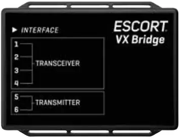
- The Shifter VX Bridge Box supports up to 6 VX Laser Shifters. It will support 4 VX Transceiver laser shifters (transmits and receives) and 2 VX Transmitter laser shifters (transmit only).
The Redline Ci 360c ships with three VX Transceiver shifters and two VX Transmitter shifters. Typical configurations are 3 Laser shifters in the front (2 transceivers, 1 transmitter) and 2 Laser shifters in the rear (1 transceiver, 1 transmitter). The individual ports for all laser shifters may be configured front or rear.
It ships with factory settings for (Transceiver Port 1 and Port 2 front, Port 3 rear, Port 4 front) and (Transmitter Port 5 front and Port 6 rear). The transceiver and transmitter connecters have different polarity plugs to prevent from connecting them to the wrong port. Please identify these by the connector type first before installing.
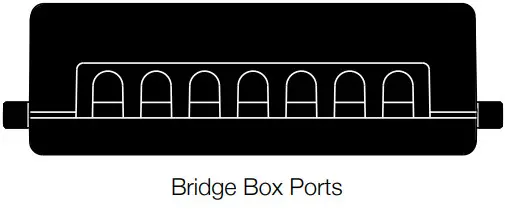
- The Shifter VX Bridge Box is weatherproof. To limit the number of cables routed through the firewall, we recommend installing the Bridge Box inside of the engine compartment.
- The Shifter VX cables come standard with connectors that screw together to create a watertight seal. The included accessories kit also includes a plastic cap which should be used if there is an unused port (e.g. port four is typically unused in the 5 shifter configuration). Alternatively, if the cap is lost heat shrink may be used to seal the unused port. Secure the cables with zip-ties. Although waterproof, it is best to locate the inline connector in a dry area and keep it protected from moving parts, road
debris, and hot surfaces such as the radiator and radiator hoses. We recommend using drip loops on either side of the inline connector to reduce the risk of water ingress. - Front Laser Shifter VX Sensors

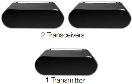
The shifters look identical from the front.
Please identify these by the connector type first before installing.
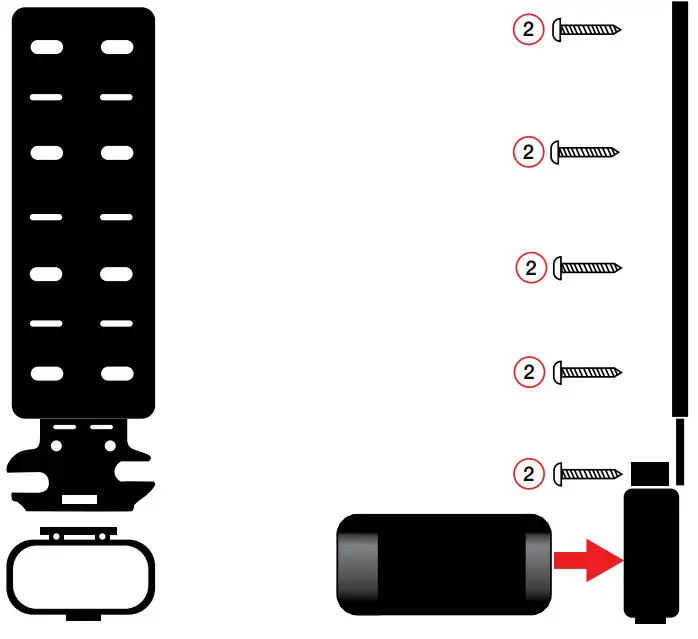
Positioning Sensors
Install each sensor halfway between the side and the center of the vehicle.
For optimal performance sensors need to be completely unobstructed, not behind a grille, level and facing straight forward (rearward if installing optional rear sensors*). Make sure that each sensor is parallel with the road (using supplied bubble level).
See the illustration on page 12 and 13 for details.
- Snap mounting bracket onto sensor and install the included bolts but do not tighten them.
If the bolts do not thread into the sensor then you have the bracket on backwards.
- Check front alignment and mount the sensor to a solid surface of the vehicle.
- Use the supplied bubble level to ensure the sensor is parallel to the road and tighten the sensor’s mounting bracket bolts.

- Repeat for additional sensor(s).

IMPORTANT! The Shifter VX sensors are shipped in “receive only” mode. Shifting must be enabled in the bands settings. See the Preferences section of the Owner’s Manual.
Rear Laser Shifter VX Sensors (optional on Redline Ci-c)
Follow instructions above to install rear sensors. See illustrations on pages 12 and 13 for positioning.
Securing Connectors with Shrink Tube
Once you’ve installed all components properly and tested to ensure all parts are working properly, use cable ties to fasten sensor cables to a solid surface, keeping them away from heat and any moving parts. It is advisable to use the supplied heats rink tubes to protect connectors against water, moisture, dust, etc.
IMPORTANT! The Shifter VX sensors are shipped in “receive only” mode. Shifting must be enabled in the bands settings. See the Preferences section of the Owner’s Manual.
GPS Antenna (Yellow Shrink)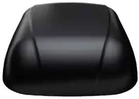
- Determine the best location for the GPS antenna. The GPS Antenna requires a clear view of the sky. The magnetic base can be used on most vehicles to mount to the roof of the car or the trunk lid. It can also be mounted to the dashboard or rear deck using double-sided tape.
- Mount the GPS Antenna, being sure that roof racks or other obstructions do not block its view of the GPS satellites.
- Locate a suitable entry point into the vehicle. Refer to the Installation Tips section for locating a suitable entry point.
- Route the cable through the entry point and secure along its path. If mounting near the front or rear window, it is usually possible to tuck the cable under the gasket surrounding the glass.
- Once inside the vehicle’s interior, route the cable to the Interface and plug into the connector labeled “GPS.”
- Secure and conceal the cable under interior trim panels.
Display Module (Orange Shrink)
- Determine the best location for the Display Module. If installed by a professional, the customer should be consulted. An optimal location is clearly visible from the driver’s position and does not take a driver’s eyes off the road for more than a moment.
- Clean the mounting surface thoroughly.
- Mount the Display using the pre-applied adhesive.
- Route the cable to the Interface and plug into the connector labeled “Display Module.”
- Secure and conceal the cable under trim panels. Display Bezel Mounting
- The supplied display bezel can be used to mount the Display permanently in the dash or console.
- Determine the best location for the Display Module. If installed by a professional, the customer should be consulted. A flat, plastic surface with no obstructions behind it is best for this type of mounting.
- Cover the mounting surface with masking tape to prevent accidental scratches.
- Using the supplied hole template, mark the location.
- Ensure there are no hidden cables, brackets, or other components behind the location, and that there is adequate clearance behind the panel. The display will protrude into the dash or console by 1/2″.
Display Bezel Mounting (continued) - Very carefully cut the hole in the mounting surface.
- Feed the display module cable through the bezel and the opening in the dash then route it to the interface.
- Remove the masking tape protecting the trim panel.
- Clean the mounting surface thoroughly.
- Apply the double-sided adhesive tape to the display bezel.
- Mount the Display Module using the bezel adhesive.
- Plug the connector into the Interface connector labeled “Display Module.”
- Secure and conceal the cable under trim panels.
Control Module (Blue Shrink)
- Determine the best location for the Control Module. If installed by a professional, the customer should be consulted. An optimal location is easily visible and accessible from the driver’s position, and does not interfere with normal driving. Avoid locations that require reaching through or around the steering wheel.
- Clean the mounting surface thoroughly.
- Mount the Control using the pre-applied adhesive.
- Route the cable to the Interface and plug into the connector labeled “Control Module.”
- Secure and conceal the cable under trim panels.
Concealed Alert Indicator (Gray Shrink)
- Determine the best location for the Alert Indicator. If installed by a professional, the customer should be consulted. An optimal location is clearly visible from the driver’s position and does not take a driver’s eyes off the road for more than a moment.
- Ensure there are no hidden cables, brackets, or other components behind the mounting location, and that there is adequate clearance behind the panel.
- Cover the mounting surface with masking tape to prevent accidental scratches.
- Carefully mark the location and drill a 1/4” hole through the mounting panel.
- Remove the masking tape protecting the trim panel.
- From the front side, snap one of the panel bezels provided into the hole.
- Snap the Alert Indicator into the panel bezel from the back side.
- Route the cable to the Interface and plug into the connector labeled “Concealed Alert LED.”
- Secure and conceal the cable under trim panels.
Rear Radar Receiver* (Optional)
- Follow the same installation instructions as for the Front Radar Receiver but with the receiver’s arrow oriented to point out the rear of the vehicle.
- Entry points to the vehicle’s interior may be available behind the license plate or lights.
Rear Laser Shifter VX Sensors* (Optional)
IMPORTANT! When using optional Rear Shifter VX sensors* ensure DIP switches 3 and 4 are moved down to the REAR SHIFTER position. See the Interface illustration on page 13.
- Follow the same installation instructions as for the Front Laser Shifter VX Sensors but with the sensors oriented to point out the rear of the vehicle.
- Entry points to the vehicle’s interior may be available behind the license plate or lights.
* Included with ESCORT Redline Ci 360c
Radio Mute Cable
- The radio mute cable (included) allows the detector to be connected to compatible audio systems with a “Radio Mute” wire or connector. Once connected, the audio level of the stereo is reduced automatically during an alert.
- Please refer to your audio system’s manual for proper connection to your audio system.
Operation Test
After all components are installed correctly:
- Turn ESCORT Redline Ci-c on by turning on the vehicle’s ignition and, if necessary, press the power button on the Control Module.
- ESCORT Redline Ci-c will cycle through a startup sequence.
- If any error messages come up, see the Owner’s Manual troubleshooting section for suggested solutions.
USB Update Cable
The USB Update cable allows updating the ESCORT Redline Ci-c’s DEFENDER database and firmware. Redline Ci-c’s red light and speed camera DEFENDER database is easily updated using our exclusive detector software tools found on our web site. Firmware, or the operating software for the detector, can also be updated using these tools.
In order to have access to these updates, please register your ESCORT Redline Ci-c at www.escortradar.com. Once registered, you will receive email notifications when updates are available.
If you have any questions, please call or visit our website. One of trained radar specialists will be happy to assist you: 800.433.3487 or escortradar.com.
 Operation
How To Use Preferences
To access the Preferences menu, press and hold both the SEN and MUTE buttons. ESCORT Redline Ci-c will display “Preferences,” indicating that it is in program mode.
Once in Preferences mode, the SEN button is used to review the preference categories, and the Up and Down buttons are used to change the individual settings within the selected category.
To exit the Preferences menu, press the power button or simply wait a few seconds without pressing any button. A “Completed” message will display, confirming your selection(s).
| User Mode | Advanced* Novice | Access and customize all Settings and Preferences Access and customize Units and Display Color only, (all other Settings are set to factory defaults) NOTE: Switch back to Advanced Mode to view all Preferences. |
| Pilot Mode | Scanning* Full Word | Scanning bar with Full Word Full Word: Highway, Auto, Autonoe, or Autoloom |
| Arrow Mode | Single* Multiple Band | Displays a single threat-direction arrow for the primary alert Displays threat-direction arrows for multiple alerts Primary alert = flashing arrow, Secondary alert = solid arrow Displays color-coded threat-direction arrows for multiple alert bands X band = green, K band = blue, Ka band / Laser = red |
| Display Color | Red*/Green/Blue/Amber | Set color to match your vehicle’s dash instrumentation |
| Speed Display | On* off | Displays current speed Displays battery voltage |
| Cruise Alert | 20 mph* Off/20-160 mph | Offers only double beep alert tones below the specified speed |
| Over Speed | 70 mph* Off/20-160 mph | Alerts when the specified speed is exceeded |
| Over Sped Limit | Off/Sped Limit*/5 Over/ 7 Over/10 Over/15 Over/ 20 Over/25 Over | Alerts when the specified speed over the speed limit has been exceeded NOTE: only applicable when connected to a mobile Wi-Fi hotspot |
| Meter Mode Tones | Standard Standard FR1* Standard FR2 Spec FR1 Spec FR2 Expert FR Simple Standard* Standard + Mild | Displays primary alert band with front signal strength bar graph Displays primary alert band and signal counter with front and rear signal strength bar graphs Primary and secondary alert bands, with front and rear bar graphs of signal strength Displays primary alert band, numeric frequency and signal counter with front and rear signal strength bar graphs Displays primary alert band, numeric frequency and signal counter with front and rear signal strength bar graphs for primary and secondary alerts Displays up to four alert bands with front and rear signal strength bar graphs for each Caution (if traveling below Cruise Alert limit) Slow Down (if traveling above Cruise Alert limit) Standard ESCORT alert tones Standard ESCORT alert tone for primary alert and double-beep tones for additional alerts Mild door bell chime alert tones |
| Auto Mute | Low/Med*/High/Off | Automatically reduces audio to preferred volume during alert |
| Auto Learn | On* / Off | Automatically stores and locks out false alarms |
| Units | English* / Metric | Units for distance and speed |
| Language | English* / Espanol | Language for voice and text |
| Voice | On* / Off | Voice announcements |
| GPS Filter | On* / Off | Enables GPS-powered features |
| Auto Power | Off 2 Hours 4 Hours* 8 Hours | When installed to a switched power supply, powers off with the vehicle’s ignition Powers off automatically after 2 hours Powers off automatically after 4 hours Powers off automatically after 8 hours NOTE: Auto Power only works with constant power-ignition. If Auto Power is on, the display screen goes blank after 30 minutes to save screen life. Display screen will turn on automatically after you reach 10 mph |
| Band Enables | Default* Modified | Default Settings for North America Customize the bands you want to monitor |
| Press MUTE to go from one category to the next | Press Up or Down to change your setting within a category | |
| X Band K Band | On* / Off On* / Off | Covers frequency range: 24.050 – 24.250 GHz NOTE: When K Band is off, K Narrow bands are available selections |
| K Narrow 1 K Narrow 2 K Narrow 3 K Narrow 4 Multan Radar C Multan Radar CT Mesta Fusion Ka Band | On* / Off On* / Off On* / Off On / Off* On / Off* On / Off* On / Off* On / Off* | Covers frequency range: 24.050 – 24.110 GHz Covers frequency range: 24.110 – 24.175 GHz Covers frequency range: 24.175 – 24.250 GHz Covers frequency range: 23.950 – 24.050 GHz Multan Radar CD detection Multan Radar CT detection Mesta Fusion detection Covers frequency range: 33.400 – 36.000 GHz NOTE: When Ka Band is off, Ka Narrow bands are available selections |
| Ka Narrow 1 Ka Narrow 2 Ka Narrow 3 Ka Narrow 4 Ka Narrow 5 Ka Narrow 6 Ka Narrow 7 Ka Narrow 8 Ka Narrow 9 Ka Narrow 10 Ka-POP Laser TSR | On / Off* On* / Off On / Off* On / Off* On* / Off On / Off* On / Off* On* / Off On / Off* On / Off* On / Off* On* / Off On* / Off | Covers frequency range: 33.400 – 33.700 GHz Covers frequency range: 33.700 – 33.900 GHz Covers frequency range: 33.900 – 34.200 GHz Covers frequency range: 34.200 – 34.600 GHz Covers frequency range: 34.600 – 34.800 GHz Covers frequency range: 34.800 – 35.160 GHz Covers frequency range: 35.160 – 35.400 GHz Covers frequency range: 35.400 – 35.600 GHz Covers frequency range: 35.600 – 35.840 GHz Covers frequency range: 35.840 – 36.000 GHz |
| Shifters | Receive/Shift*/Shift4/ Shifter mode Shift6/Shift8/Shift10/Off | Receive = receive-only Shift4/6/8/10 puts shifters in receive-only mode after 4/6/8/10 seconds from receiving an alert NOTE: only available when VX shifters are connected |
| Shifters | Receive/Shift*/Shift4/ Shifter mode Shift6/Shift8/Shift10/Off | Receive = receive-only Shift4/6/8/10 puts shifters in receive-only mode after 4/6/8/10 seconds from receiving an alert NOTE: only available when VX shifters are connected |
| Marker Enables | Default* Modified | Default settings Customize the types of locations you want alerted to |
Notes: For descriptions of features and functions available when connected to Drive Smarter ® , visit EscortRadar.com
To view serial number and software revision press MRK and SEN while powering on detector.
To restore ESCORT Redline Ci to its original factory settings, press and hold MRK and BRT while turning the power on. A Restored message will display, acknowledging the
reset.
| Press MUTE to go from one category to the next | Press Up or Down to change your setting within a category | |
| Other Relight Red & Speed Speed Camera Speed Trap Air Patrol | On* /Off On* / Off On* / Off On* / Off On* / Off On / Off* | Other location Red light camera Red light & speed camera Speed camera Speed trap Known aircraft patrolled areas NOTE: User cannot mark an Air Patrol location |
| Clear Locations | Marked Lockouts Defender Format | Clear all user-marked locations. Press MUTE button to confirm Clear all lockouts. Press MUTE button to confirm Clear all DEFENDER Database data. Press MUTE button to confirm Clear DEFENDER Database, all markers, and all lockouts. Press MUTE button to confirm |
| Wi-Fi Bluetooth Auto Update WiFi Update | On* / Off On* / Off Off / Database/ Firmware/All* Database/Firmware | Allows connection to a Wi-Fi hotspot Allows connection to the Drive Smarter app Automatically checks for the selected updates when connected to a Wi-Fi hotspot Perform an update to the selected software |
PROGRAMMING MENU
Overview
To access the programming menu, press the SEN and BRT buttons. Press the SEN button to changed the selected menu item. Use the – or + button to change the setting on the selected menu item. Press the SEN button again to return to the selected Menu item.
To exit Programming, press the power button or simply wait a few seconds without pressing any buttons. A “Completed” message will display, confirming your selection(s).
Restore Factory Settings
To restore Redline Ci-c to its original factory settings:
- Press and hold MRK and BRT while turning the power on.
- Restore Factory Settings? will display.
- Press the MUTE button to confirm. To cancel, wait 10 seconds.
- Factory Settings Restored will display and Redline Ci-c will reboot.
- You will be prompted to select your Time Zone and the Daylight Saving Time setting.
The following is a list of all settings available in the Programming menu followed by detailed descriptions of each setting.
Serial Number and Software Version
To view your Redline Ci-c’s serial number and software revision, press and hold the MRK and MUTE buttons while powering on the detector.
User Mode
Advanced Access and customize all settings and preferences.
Novice Access and customize only Units (English or metric) and Display Color. All other preferences are set to factory defaults. To view all settings and preferences, you must switch to Advanced mode.
UNDERSTANDING YOUR DETECTOR
How Radar Works
Traffic radar, which consists of microwaves, travels in straight lines and is easily reflected by objects such as cars, trucks, even guardrails and overpasses. Radar works by directing its microwave beam down the road. As your vehicle travels into range, the microwave beam bounces off your car, and the radar antenna looks for the reflections.
Using the Doppler Principle, the radar equipment then calculates your speed by comparing the frequency of the reflection of your car to the original frequency of the beam sent out.
Traffic radar has limitations, the most significant of these being that it typically can monitor only one target at a time. If there is more than one vehicle within range, it is up to the radar operator to decide which target is producing the strongest reflection. Since the strength of the reflection is affected by both the size of the vehicle and its proximity to the antenna, it is difficult for the radar operator to determine if the signal is from a sports car nearby or a semi-truck several hundred feet away. Radar range also depends on the power of the radar equipment itself. The strength of the radar unit’s beam diminishes with distance. The farther the radar has to travel, the less energy it has for speed detection.
Because intrusion alarms and motion sensors often operate on the same frequency as X, and K-band radar, your detector will occasionally receive non-police radar signals. These transmitters generally produce much weaker readings than will a true radar encounter.
As you become familiar with the sources of these pseudo alarms in your daily driving, they will serve as confirmation that your device’s radar detection abilities are fully operational.
How Laser (Lidar) Works
Laser speed detection is actually light detection and ranging (LIDAR). Laser guns project a beam of invisible infrared light. The signal is a series of very short infrared light energy pulses that move in a straight line, reflecting off your car and returning to the gun. Laser uses these light pulses to measure the distance to a vehicle. Speed is then calculated by measuring how quickly these pulses are reflected, given the known speed of light.
Laser is a newer technology whose use is not as widespread as conventional radar; therefore, you may not encounter it on a daily basis. And unlike radar detection, laser is not prone to false alarms. Because laser transmits a much narrower beam than does radar, it is much more accurate in its ability to distinguish between targets and is also more difficult to detect. As a result, even the briefest laser alert should be taken seriously. There are limitations to laser, however. Laser is much more sensitive to weather conditions than radar, and a laser gun’s range will be decreased by anything affecting visibility, such as rain, fog or smoke. A laser gun cannot operate through glass, and it must be stationary to get an accurate reading. Because laser must have a clear line of sight and is subject to cosine error (an inaccuracy that increases as the angle between the gun and the vehicle increases), police typically use laser equipment parallel to the road or from an overpass. Laser can be used day or night.
TSR Signal Ranking Software
Your radar detector includes an optional boost in antifelting software to eliminate excessive alerts from erroneous K-band sources. One example of this is traffic flow monitoring systems. These systems, which are becoming more widely used in several countries, generate K-band signals to measure the flow of traffic on a given road. Unfortunately most detectors see this as a real threat and will alert you to it unnecessarily. Our proprietary TSR software, intelligently sorts, ranks and rejects this type of false alarm automatically. The result is ultimate protection without excessive false alarms.
ALERTS Standard
The Standard meter mode provides only the band information and front signal strength information of a single alert. When radar is detected, the band (X, K or Ka) and a bar graph of the signal’s strength are displayed.
When laser is detected, the display will simply read “Laser.” If there are multiple alerts present, only the highest priority threat is displayed. Laser is the highest priority threat, followed by Ka, K, then X band radar.
Standard FR

The Standard FR meter mode displays the band of the highest priority threat along with a front and rear bar graph of its signal strength.. The left bar graph shows the signal strength in front of the detector while the right bar graph shows the signal strength from the rear. If there are multiple alerts present, only the signal strength of the highest priority threat is displayed. Laser is the highest priority threat, followed by Ka, K, then X band radar. The number in between the bar graphs is the total number of alerts that are being detected.
Spec FR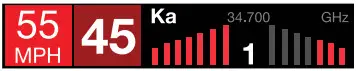 The Spec FR meter mode displays the numeric frequency and band of the highest priority threat along with a front and rear bar graph of its signal strength. The left bar graph shows the signal in front of the detector while the right bar graph shows the signal strength from the rear. If there are multiple alerts present, only the signal strength of the highest priority threat is displayed. Laser is the highest priority threat, followed by Ka, K, then X band radar. The number in between the bar graphs is the total number of alerts that are being detected.
Expert FR
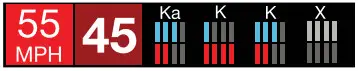
Expert FR meter mode (FR = Front and Rear signal strengths) simultaneously tracks up to four radar alerts displaying each alert’s band along with a bar graph of their front and rear signal strengths. When using this meter mode the rear signal strength bar graph is always the opposite color of the selected display color. In the above image, a Ka band, two K bands, and an X band signal are being detected. The X band alert is grey to show that it is a locked out false alert. For more information about locking out false alerts see the GPS Filtering/True Lock section. Expert FR meter mode can help you spot a change in your normal driving environment (e.g., a traffic radar unit being operated in an area where there are normally other signals present).
Simple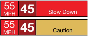
Simple messages replace bands and signal strengths or frequencies:
Caution used when an alert is received while you are traveling below your current Cruise Alert setting (or posted speed limit for your current location when connected to Drive Smarter).
Slow Down displayed when an alert is received while you are traveling above the current Cruise Alert setting (or posted speed limit of your current location, when connected to Drive Smarter).
TONES
Standard
The factory default Standard alert tones uses a Geiger counter-type sound to indicate the signal strength and type of radar signal being encountered. When you encounter radar, a distinct audible alert will sound and will increase as the signal gets stronger. This allows you to judge the distance from the signal source without taking your eyes off of the road. Each band has a distinct tone for easy identification:
X band = beep tone
K band = brad tone
Ka band = double-brad tone Laser = solid brad tone
POP = solid brad tone
Standard Plus
Features the Standard alert tones outlined above for the primary alert, plus double-beep tones for additional alerts.
Mild
Mild alert tones offer softer, simpler alert tones that are less obtrusive to the driving experience:
X band, K band, Ka band and POP = Doorbell chime
Low signal strength = Double chime
High signal strength = Triple chime
If alert remains in area more than 15 seconds = Single chime (as a reminder)
Laser = Solid brad tone
Since laser signals are a possible threat no matter how weak, laser alerts are always full strength.
Auto Mute
Your Redline Ci-c also includes ESCORT’s patented Auto Mute feature. Once Redline Ci-c alerts you to a radar encounter at your selected volume level, it automatically reduces the volume to the selected Auto Mute level. This keeps you informed without the annoyance of a continuous full-volume alert. If you prefer, you can turn the Auto Mute feature off.
Auto Learn™ Intelligence
The Auto Learn feature analyzes (over time) the source of radar signals by location and frequency. This allows Redline Ci-c to determine if a fixed location signal is a real threat or a false one. If it determines that the signal is an automatic door opener, motion sensor, etc., it automatically locks out this source at this particular location. A “Stored” message will appear on the display when a signal has been automatically locked out. Auto Learn needs to encounter the exact frequency in the same location approximately three times to lock it out. Since some door openers are turned on and off routinely, some variations may occur. Variations may also occur with seasonal temperature changes that can affects the frequency that these radar sources transmit.
Redline Ci-c will also unlearn signals to protect you from locking out real threats. If a particular signal is no longer present at a location that was previously locked out, Redline Ci-c will unlock that signal. If you prefer, you can turn the Auto Learn feature off.
GPS Filter (True Lock)
Redline Ci-c is equipped with a True Lock GPS Filter to store and lock out, or ignore, fixed location false alerts in its memory. Common sources of fixed location false alerts are storefront automatic door openers and motion sensors. The True Lock GPS Filter will not lock out moving false alerts that are commonly caused by vehicle’s blind spot monitoring and collision avoidance systems.
Locking Out False Alerts
To manually lock out a fixed location false alert (X band, K band or laser only), press the MUTE button three times during an alert. Pressing the first time will silence the audio. Pressing a second time will generate a prompt on the display that will read “Lockout?” Press a third time to confirm you want to lock this signal out by location and frequency. A “Stored” message will be displayed. Once a signal has been stored, Redline Ci-c will not audibly alert the next time you approach this area but will display the locked out alert in grey.
Locked Out Alert
To unlock a signal that has already been stored, simply press the MUTE button twice while receiving the locked out alert. The display will read “Unlock?” when pressing MUTE the first time. Press the MUTE button again to unlock it from memory. The display will read “Unlocked” to confirm your action.
Note: When the GPS Filter is set to OFF, you do not have access to Redline Ci-c’s other GPS- enabled features (e.g., Defender Database alerts, marking locations, etc.).
Auto Power
This feature automatically turns off Redline Ci-c after a set period of time to save unnecessary drain on your battery. This is especially useful if your vehicle has a constant- power ignition. To turn Redline Ci-c on again you must press the power button.
Note: If Auto Power is on, to save screen life the display screen goes blank after 30 minutes without moving. The display screen will turn on automatically after you reach 10MPH.
Band Enables
In the factory default setting the suggested radar and laser bands for North America are monitored and sources of some common false alerts are rejected. It is highly recommended that you use your Redline Ci-c in this mode.
If you modify Band Enables then this setting will show Modified. Redline Ci-c will also notify you during the startup sequence with an audible alert.
WARNING: Do not turn off any Band Enables unless you are absolutely certain there are no traffic radar guns in your area using that specific band.
K Notch
Reduces sensitivity of K band in the frequency range of 24.190 – 24.210 GHz. This is effective at reducing alerts to certain vehicle collision avoidance systems.
Shifters (only available when optional VX laser shifters are connected)
Sets the shifter mode of operation. Receive = receive-only mode. Shift4/6/8/10 puts the laser shifters into receive-only mode after 4/6/8/10 seconds from receiving an alert. After 30 seconds of not receiving a Laser alert, the shifters automatically return to shift mode. You can also manually put the laser shifters into receive-only mode by double tapping the Mute button on the detector or Smart Cord.
Marker Enables
Redline Ci-c gives advanced warning of upcoming markers at the following distances:
| Red light cameras Red light & speed cameras Speed cameras Speed traps Other | 250 ft or 10 seconds 250 ft or 10 seconds 500 ft when traveling below 55 mph 1,000 ft when traveling above 55 mph 0.3 mi or approximately 1,584 ft 500 ft when traveling below 55 mph 1,000 ft when traveling above 55 mph |
To Mark A Location
– Press MRK. The display will read “Mark?” Press MRK again to bring up a menu of markers to
– Use the Rotary Dial to scroll through the markers then press MRK to select the marker that you wish to use at this location.
– The display will read “Marked!”
Air Patrol locations cannot be marked by the user.
Note: When a location is marked the first time, you must travel at least 1 mile away from that location to receive an alert when you return to the area.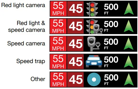
To Unmark A Location
Touch the MRK button when you are receiving a marked-location alert. The display will read “Unmark?”
Touch the MRK button again to confirm. The display will read “Unmarked!”
Clear Locations
At some point, you may wish to clear some of the data in Redline Ci’s database. This may include any of the following: Defender Database data, Marked locations or false alert lockouts.
To clear locations in the selected database, select the database then press MUTE to confirm. Format clears locations in all databases.
Wi-Fi
Turns on and off Wi-Fi connection to a hotspot.
Note: Compatible with 2.4 and 5 GHz hotspots.
 Troubleshooting
| PROBLEM | SOLUTION |
| Detector beeps briefly at the same location every day, but no radar source is in sight. | A motion sensor or intrusion alarm is located within range of your route. If you have Auto Learn enabled, the factory default setting, then Redline Ci-c will store this signal after about 3 passes and no longer alert to it. |
| Detector did not alert when a police car was in view. | Officer may not have radar or laser unit turned on. VASCAR (Visual Average Speed Computer and Recorder), a stopwatch method of speed detection, may be in use. |
| Detector’s audible alerts become softer after the first few alerts. | Detector is in Auto Mute mode. See “Auto Mute” in the Settings & Preferences section for details. |
| The power-on sequence reoccurs while you are driving. | A loose power connection can cause Redline Ci-c to be briefly disconnected and will retrigger the power-on sequence. Check all connections. |
| You wish to restore the factory default settings. | Press and hold the MRK and BRT buttons while powering on the detector. A “Factory Settings Restored” message will display, acknowledging the reset. |
| The device will not turn on. | Check that vehicle ignition is on. |
| The display is blank. | Redline Ci-c is in Dark mode. Press the BRT button to adjust the brightness. |
Trademarks Acknowledgment, Warnings, and Regulatory Information
©2023 ESCORT Inc. ESCORT®, Redline Ci-c®, Redline Ci 360c®, Defender®, Auto Learn®, Shifter VX®,
True Lock™, Auto Sensitivity™, Spec Display™, Expert Meter™, IVT Filter™, Smart Mute™ and EZ Mag Mount™ are trademarks of ESCORT, Inc.
Drive Smarter® is a registered trademark of Cedar Electronics Corporation.
Apple and the Apple Logo are trademarks of Apple Inc. Android, Google Play, and the Google Play Logo are trademarks of Google Inc.
The Bluetooth® word mark and logos are registered trademarks owned by Bluetooth SIG and any use of such marks by ESCORT Inc is under license. Ambarella, and the Ambarella Logo are trademarks of Ambarella, Inc. All other brands, product names and company names are trademarks of their respective owners.
Features, Specifications and prices subject to change without notice.
FCC NOTE: Modifications not expressly approved by the manufacturer could void the user’s FCC granted authority to operate the equipment.
FCC ID: QKLM14R CONTAINS FCC ID: VPYLBEE59B1LV
THIS DEVICE COMPLIES WITH PART 15 OF THE FCC RULES. OPERATION IS SUBJECT TO THE FOLLOWING TWO CONDITIONS: (1) THIS DEVICE MAY NOT CAUSE HARMFUL INTERFERENCE, AND (2) THIS DEVICE MUST ACCEPT ANY INTERFERENCE RECEIVED, INCLUDING INTERFERENCE THAT MAY CAUSE UNDESIRED OPERATION.
FCC Part 15.21 Warning Statement
NOTE: THE GRANTEE IS NOT RESPONSIBLE FOR ANY CHANGES OR MODIFICATIONS NOT EXPRESSLY APPROVED BY THE PARTY ESPONSIBLE FOR COMPLIANCE. SUCH MODIFICATIONS COULD VOID THE USER’S AUTHORITY TO OPERATE THE EQUIPMENT.
FCC Part 15.105(b) Warning Statement- (ONLY Required for 15.109-JBP devices)
NOTE: This equipment has been tested and found to comply with the limits for a Class B digital device, pursuant to part 15 of the FCC Rules. These limits are designed to provide reasonable protection against harmful interference in a residential installation. This equipment generates uses and can radiate radio frequency energy and, if not installed and used in accordance with the instructions, may cause harmful interference to radio communications. However, there is no guarantee that interference will not occur in a particular installation. If this equipment does cause harmful interference to radio or television reception, which can be determined by turning the equipment off and on, the user is encouraged to try to correct the interference by one or more of the following measures:
– Reorient or relocate the receiving antenna.
– Increase the separation between the equipment and receiver.
– Connect the equipment into an outlet on a circuit different from that to which the receiver is connected.
– Consult the dealer or an experienced radio/TV technician for help
Warning:
This device should be installed and operated with minimum 20 cm between the radiator and your body.
DISPOSAL OF ELECTRONICS EQUIPMENT: This product may contain hazardous substances that could impact health and the environment if not disposed of properly.![]() The crossed out wheeled bin symbol indicates that the product should not be disposed of along with household waste. It should be handed over to an applicable collection point for the recycling of electrical equipment.
The crossed out wheeled bin symbol indicates that the product should not be disposed of along with household waste. It should be handed over to an applicable collection point for the recycling of electrical equipment.
By ensuring that this product is disposed of correctly you will help/prevent potential negative impact on the environment.
If you need more information on the collection, reuse and recycling systems, please contact your local civic office or the shop where it was originally purchased.![]()
![]() Warranty
Warranty
LIMITED 3-YEAR WARRANTY
Escort, Inc. (“Escort”) warrants that this product and the component parts thereof, will be free of defects in workmanship and materials for a period of three years from the date of first consumer purchase. This warranty may be enforced by the first consumer purchaser. If the product is under warranty, it will be repaired or exchanged depending on the model as determined at Escort’s sole discretion. Such remedy shall be your sole and exclusive remedy for any breach of warranty.
The procedure for obtaining service and support, and the applicability of this warranty, will vary depending on the country or jurisdiction in which you purchased and utilize the product. For the details on obtaining product service, support and warranty please visit https://www.escortradar.com/pages/contact-us
Provided that the product is utilized within the U.S.A.- Escort will, without charge, repair or replace, at its option, defective products, products or component parts upon delivery to the Escort Factory Service department, accompanied by proof of the date of first consumer purchase, such as a duplicated copy of a sales receipt. You must pay any initial shipping charges required to ship the product for warranty service, but the return charges, to an address in the U.S.A., will be at Escort’s expense, if the product is repaired or replaced under warranty.
This warranty gives you specific legal rights, and you may also have other rights which may vary from state to state and country to country.
Exclusions: This limited warranty does not apply: 1) To any product damaged by accident; 2) In the event of misuse, ordinary wear, failure to follow directions, or improper maintenance of the product or as a result of unauthorized alterations or repairs; 3) If the serial number has been altered, defaced, or removed; 4) If the product was purchased or is utilized in a jurisdiction not covered by the limited warranty.
All implied warranties, including warranties of merchantability and fitness for a particular purpose are limited in duration to the length of this warranty. Escort shall not be liable for any incidental, consequential or other damages; including, without limitation, damages resulting from loss of use or cost of installation.
Some states and countries do not allow limitations on how long an implied warranty lasts and/or do not allow the exclusion or limitation of incidental or consequential damages, so the above limitations may not apply to you. This warranty gives you specific legal rights, and you may also have other rights which vary from state to state and country to country.
Specifications
Radar Detector Operating Frequencies:
| X band – 10.500 to 10.550 GHz |
| K band – 23.950 to 24.250 GHz |
| Ka band – 33.400 to 36.000 GHz |
| 820-950 nanometers (Laser) |
| 2.4000-2.4835 GHz (Bluetooth/Wifi) |
| RF Output Power: 0 dBm (2.4 GHz Band) |
| 5.180 – 5.825 GHz (Wifi) |
| RF Output Power: -1.45 dBm (5GHz Band) |
![]()


