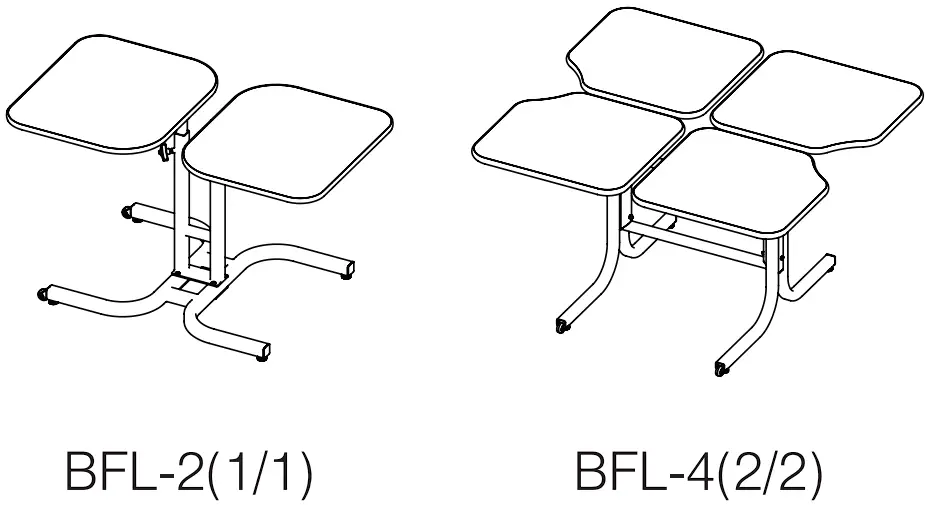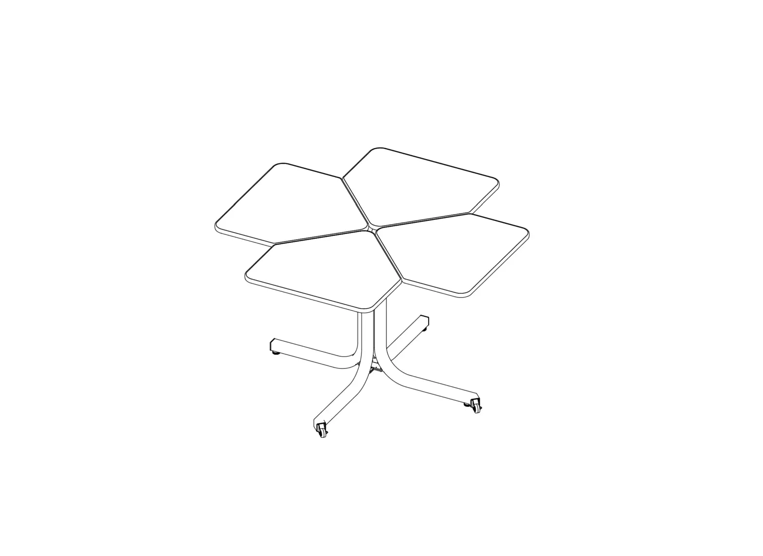
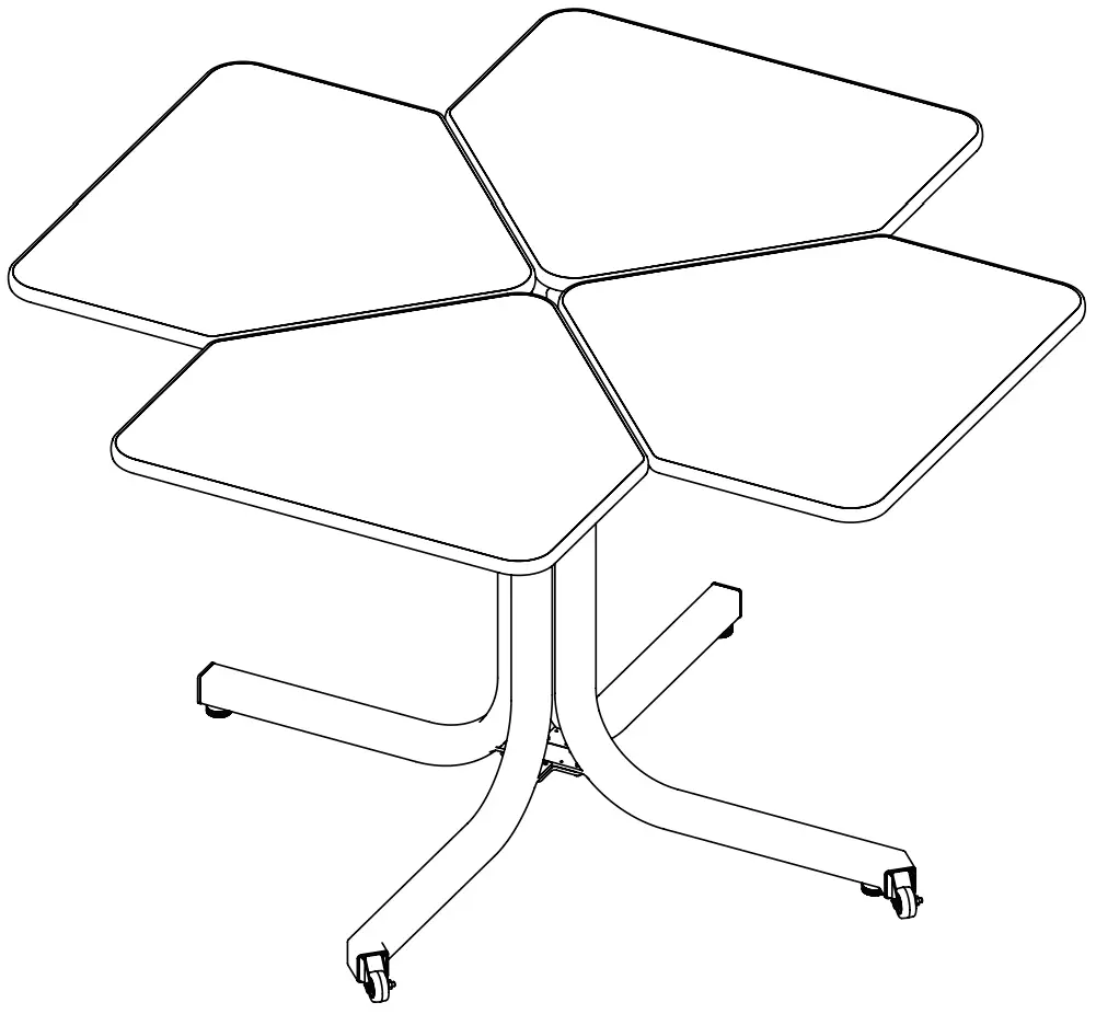
BFL-4(4/1) Butterfly Wheelchair Accessible Table
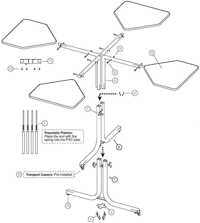
PARTS DESCRIPTION

| # | PART # | PART DESCRIPTION | QTY |
| 1 | BFL4-4151 | Base (A) | 1 |
| 2 | BFL4-4156 | Base (B) | 1 |
| 3 | BFL4-4158 | Leg Attachment Plate | 1 |
| 4 | BFL4-4160 | 1/2” Screws (12+4) | 16 |
| 5 | BFL4-4164 | Pneumatic Pistons | 4 |
| 6 | BFL4-4165 | Table Arms | 4 |
| 7 | BFL4-4166 | Adjustable Knobs | 8 |
| 8 | BFL4-4167 | 1 1/2” Hex Bolts | 8 |
| 9 | BFL4-4168 | 1/4” Hex Nuts | 8 |
| 10 | BFL4-4169 | Table Tops | 4 |
| 11 | BFL4-4174 | Table Top Mounting Brackets | 4 |
| 12 | BFL4-4175 | M6x16 Mounting Bracket Screws | 32 |
| 13 | BFL4-4176 | Transport Casters (Pre-installed) | 2 |
 | PLEASE DO A COUNT BEFORE STARTING. IF YOU NEED TO ORDER PARTS, PLEASE CONTACT TECHNICAL SUPPORT AT 1-888-678-2060. |
BASE ASSEMBLY
STEP 1
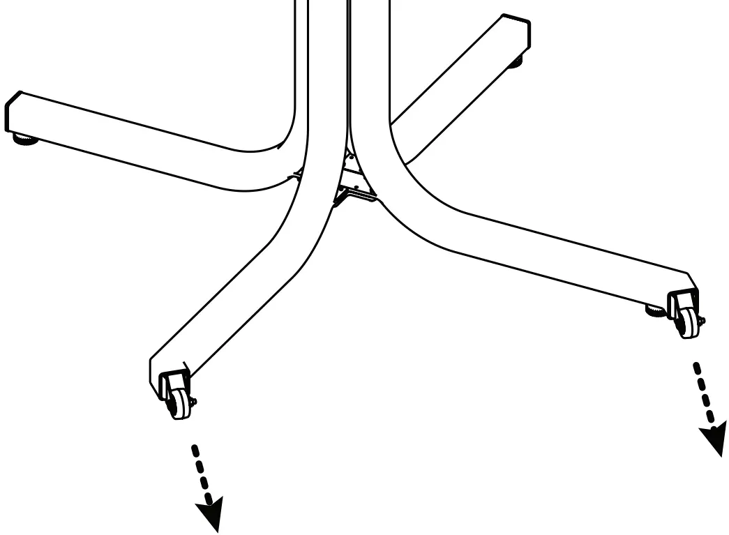
- BEFORE STARTING ASSEMBLY, PLEASE REMOVE TABLE ARMS (#6) FROM BASE A (#1) & BASE B (#2).
- IN ORDER FOR THE BFL-4(4/1) TO BE TRANSPORTED PROPERLY AND SAFELY, PLEASE MAKE SURE BOTH TRANSPORT CASTERS (#13) ARE POINTING IN THE SAME DIRECTION.
STEP 2
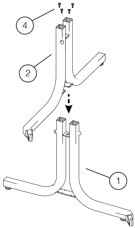
| Required Items: Base A (#1) Base B (#2) 1/2” Screw (#4) X4 |
- Place Base A (#1) onto a flat surface. Position Base B (#2) at 90 degrees to Base A (#1). Push Base B (#2) down onto Base A (#1) until the tops of the center post are flush.
Use 1/2 Screws (#4) to secure bases (Do not over tighten).
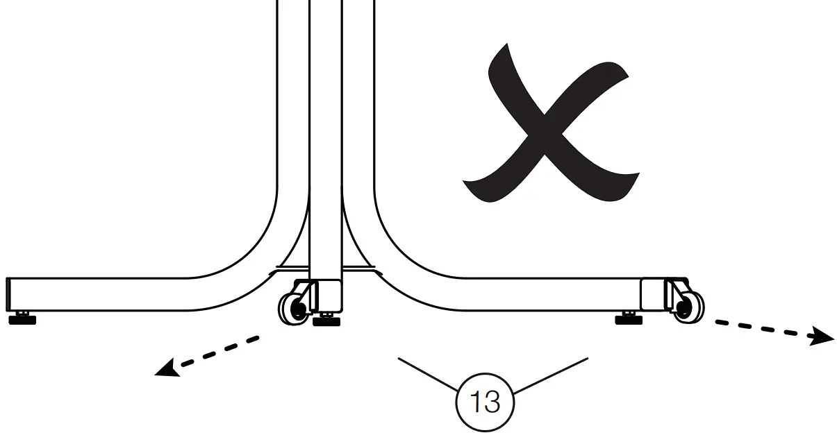
| IN ORDER FOR THE BFL-4(4/1) TO BE MOVED PROPERLY AND SAFELY, PLEASE MAKE SURE BOTH TRANSPORT CASTERS (#13) ARE POINTING IN THE SAME DIRECTION BEFORE PROCEEDING. IF NECESSARY, PLEASE SEE STEP 1. |
BASE PLATE ASSEMBLY
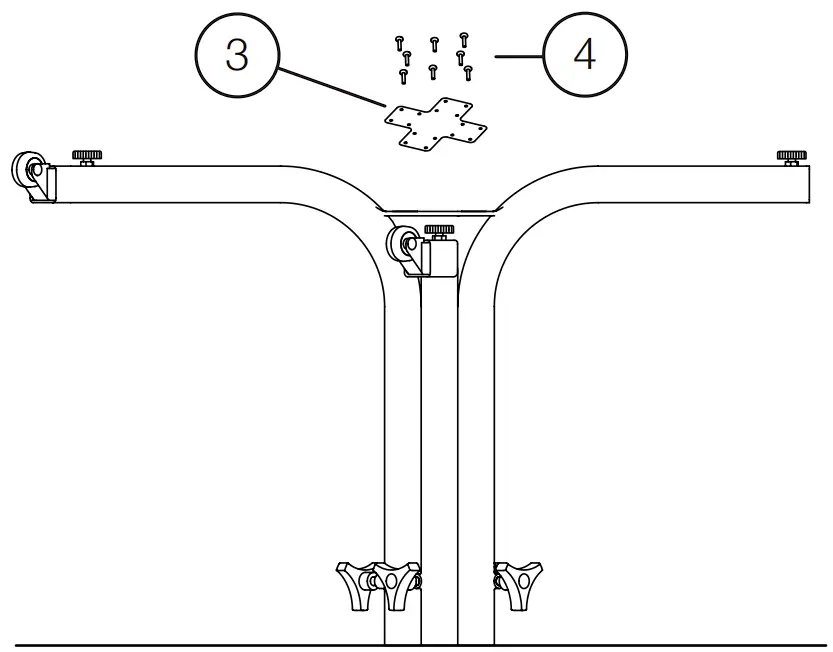
| Required Items: Leg Attachment Plate (#3) 1/2” Screw (#4) X12 |
- Tip the entire assembly over (legs in air). Secure Bases together by bolting the Attachment Plate to the underside of Base A (16 screws). Tighten screws securely.
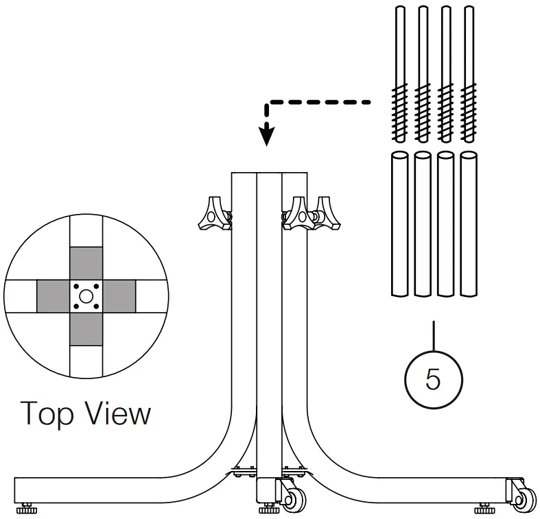
| Required Items: Pneumatic Pistons (#5) X4 |
| Pneumatic Pistons: Place the end with the spring into the PVC tube before inserting into frame. |
- Tip the frame, placing it on its legs. Place Pneumatic Pistons (#5) into frame tubes. These pistons are helpful when adjusting the height of each table top.
TABLE TOP / MOUNTING BRACKET ASSEMBLY
| Required Items: Table Tops (#10) X4 Table Top Mounting Brackets (#11) X4 M6x16 Mounting Bracket Screws (#12) X32 |
- Lay Table Top (#10) on a level floor with pre-drilled holes pointing up. Using the Allen Wrench provided, secure Table Top Mounting Bracket (#11) using the M6x16 Mounting Bracket Screws (#12). Repeat on all Table Tops (#10).

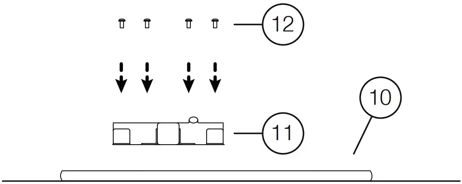
TABLE TOP ASSEMBLY
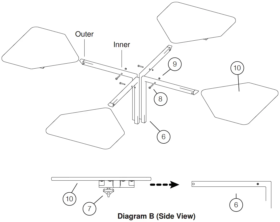
| Required Items: Table Arms (#6) X4 Adjustable Knobs (#7) X4 1 1/4” Bolts (#8) X8 1/4” Nuts (#9) X8 Table Tops (#10) X4 |
- Insert Table Arms (#6) into the assembled base. Ensure the “L” shaped bracket is held to one side while inserting the arm tops into the center post.
- Insert 1 1/4” Bolts (#8) into Table Arm (#6) and tighten with 1/4“ Nut (#9).
Start with inner pre-drilled hole – this is to stop the Table Tops from hitting the arm. Repeat on all four Table Arms. - Slide Table Tops (#10) onto Table Arms – See Diagram B. Use Adjustable Knobs (#7) to secure tops.
- Insert 1 1/4” Bolts (#8) into outer pre-drilled hole of Table Arm (#6). Tighten with 1/4” Nut (#9) – this is to stop the Table Tops from sliding off the arm.
FINAL ADJUSTMENTS
- Use Adjustment Knobs (#7) to secure the table tops at the desired height.
- Operation: Two offset casters have been provided to ensure easy & safe relocation of the table. To move the table, lift the table from opposite side of the casters by 10” off the floor. Adjust glides to level & stabilize the table. Secure by tighten the locking nut.
BFL-4(4/1) SPECIFICATIONS
OVERALL: 48” X 48” (EXTENDED – 58” X 58”)
INDIVIDUAL TOP: 26”W X 22”D
HEIGHT ADJUSTMENT: 26” – 36”
20” – 30” – OPTIONAL
ADDITIONAL MODELS: