![]() CMOS 16-BIT DMM MICROCONTROLLER BOARD
CMOS 16-BIT DMM MICROCONTROLLER BOARD
S5U1C17M03T Manual
(Software Evaluation Tool for S1C17M03)
S5U1C17M03T Cmos 16-Bit Dmm Microcontroller Board
Evaluation board/kit and Development tool important notice
- This evaluation board/kit or development tool is designed for use with engineering evaluation, demonstration, or development purposes only. Do not use it for other purposes. It is not intended to meet the design requirements of finished products.
- This evaluation board/kit or development tool is intended for use by an electronic engineer and is not a consumer product. The user should use it properly and in a safe manner. Seiko Epson does not assume any responsibility or liability of any kind of damage and/or fire caused by its use. The user should cease to use it when any abnormal issue occurs even during proper and safe use.
- Parts used for this evaluation board/kit or development tool may be changed without any notice.
NOTICE : PLEASE READ THE FOLLOWING NOTICE CAREFULLY BEFORE USING THIS DOCUMENT
The contents of this document are subject to change without notice.
- This document may not be copied, reproduced, or used for any other purpose, in whole or in part, without the consent of the Seiko Epson Corporation (“Epson”).
- Before purchasing or using Epson products, please contact our sales representative for the latest information and always be sure to check the latest information published on Epson’s official web sites and other sources.
- Information provided in this document such as application circuits, programs, usage, etc., are for reference purposes only. Using the application circuits, programs, usage, etc. in the design of your equipment or systems is your own responsibility. Epson makes no guarantees against any infringements or damages to any third parties’ intellectual property rights or any other rights resulting from the information. This document does not grant you any licenses, intellectual property rights or any other rights with respect to Epson products owned by Epson or any third parties.
- Epson is committed to constantly improving quality and reliability, but semiconductor products in general are subject to malfunction and failure. By using Epson products, you shall be responsible for your hardware. Software and systems must be designed well enough to prevent death or injury as well as any property damage even if any of the malfunctions or failures might be caused by Epson products. When designing your products using Epson products, please be sure to check and comply with the latest information regarding Epson products (this document, specifications, data sheets, manuals, Epson’s web site, etc.). When using the information included above materials such as product data, charts, technical contents, programs, algorithms and application circuit examples, you shall evaluate your products both on a stand-alone basis as well as within your overall systems. You shall be solely responsible for deciding whether or not to adopt and use Epson products.
- Epson has prepared this document and programs provided in this document carefully to be accurate and dependable, but Epson does not guarantee that the information and the programs are always accurate and complete. Epson assumes no responsibility for any damages which you incur due to misinformation in this document and the programs.
- No dismantling, analysis, reverse engineering, modification, alteration, adaptation, reproduction, etc., of Epson products is allowed.
- Epson products have been designed, developed and manufactured to be used in general electronic applications (office equipment, communications equipment, measuring instruments, home electronics, etc.) and applications individually listed in this document (“General Purpose”). Epson products are NOT intended for any use beyond the General Purpose uses that requires particular/higher quality or reliability in order to refrain from causing any malfunction or failure leading to death, injury, serious property damage or severe impact on society, including, but not limited to those listed below. Therefore, you are advised to use Epson products only for General Purpose uses. Should you desire to buy and use Epson products for a particular purpose other than a General Purpose uses, Epson makes no warranty and disclaims with respect to Epson products, whether express or implied, including without limitation any implied warranty of merchantability or fitness for any particular purpose. Please be sure to contact our sales representative and obtain approval in advance.
【Particular purpose】
Space equipment (artificial satellites, rockets, etc.)
Transportation vehicles and their control equipment (automobiles, aircraft, trains, ships, etc.)
Medical equipment (other than applications individually listed in this document) / Relay equipment to be placed on ocean floor Power station control equipment / Disaster or crime prevention equipment / Traffic control equipment / Financial equipment Other applications requiring similar levels of reliability as those listed above - Epson products listed in this document and our associated technologies shall not be used in any equipment or systems that laws and
regulations in Japan or any other countries prohibit to manufacture, use or sell. Furthermore, Epson products and our associated technologies shall not be used for developing weapons of mass destruction, or any other military purposes or applications. If exporting Epson products or our associated technologies, you shall comply with the Foreign Exchange and Foreign Trade Control Act in Japan, Export Administration Regulations in the U.S.A. (EAR) and other export-related laws and regulations in Japan and any other countries and follow the required procedures as provided by the relevant laws and regulations. - Epson assumes no responsibility for any damages (whether direct or indirect) caused by or in relation with your non-compliance with the terms and conditions in this document.
- Epson assumes no responsibility for any damages (whether direct or indirect) incurred by any third party that you assign, transfer, loan, etc., Epson products to.
- For more details or other concerns about this document, please contact our sales representative.
- Company names and product names listed in this document are trademarks or registered trademarks of their respective companies.
Overview
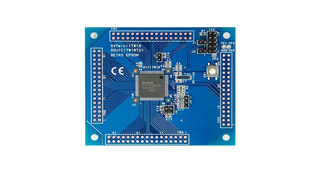
The S5U1C17M03T (SVT board) is equipped with a 16-bit MCU S1C17M03 for Seiko Epson digital multimeters (DMM).
The SVT board is equipped with the functions required for a DMM and can measure voltage, current, resistance, capacitance, continuity check, diodes, and frequencies.
1.1 Board external view
Figuer1.1.1 shows an external view of the SVT board.
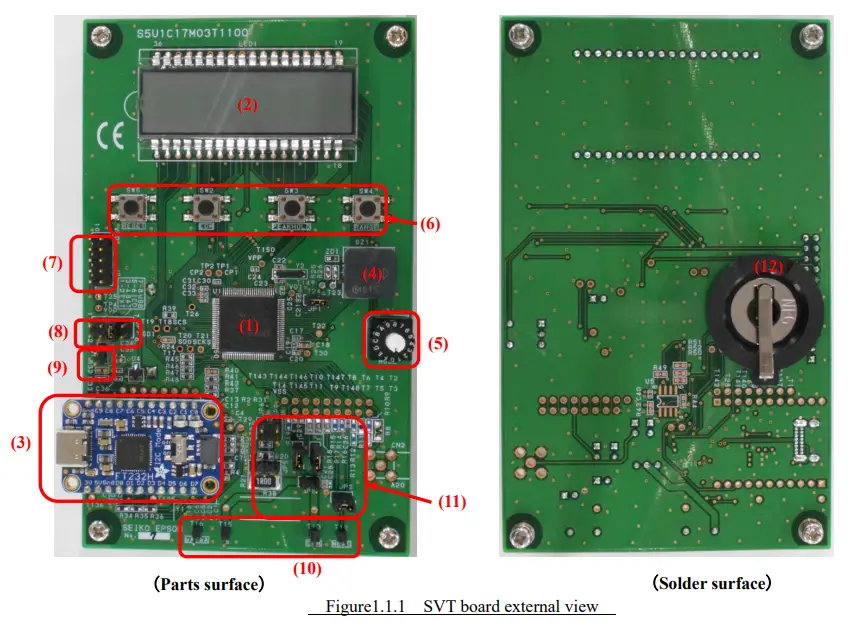
| (1) S1C17M03 16-bit MCU (2) LCD module (8digits、14segments / digit) (3) USB⇔SPI bridge IC module USB Type-C connector (4) Piezo electric buzzer (5) Mode switching rotary switch (6) Tactile switch | (7) S5U1C17001H3 (ICDmini Ver.3 Emulator connector (8) Power selection connector (9) External power input connector (10) Voltage, current, resistance, capacitance, continuity check, diodes, and frequencies measurement terminal (11) Setting jumper pins (12) CR2032 button battery holder |
Specification
The product specifications of the SVT board are shown in Table2.1, and the measurement specifications are in Table2.2.
Table 2.1 Product specifications
| Model | S5U1C17M03T |
|
Power | EXT : External BAT : CR2032 (3V) Lithium battery x1 ICD : Emulator USB: USB VBUS |
| Size | W80×H130×D17.1 (Without spacers) |
| Weight | 60g (Without battery and spacers) |
Table 2.2 Measurement specification
| Measurement mode | Measurement range |
| DC voltage | 600m/6/60V * |
| AC voltage | 600m/6/60V * |
| DC current | 600u/6m/60mA* |
| AC current | 600u/6m/60mA* |
| Resistance | 600/6k/60k/600k/6M/60MΩ |
| Capacitance | 10n/100n/1u/10u/100u/1000uF |
| Frequencies | 5Hz – 100kHz |
| Continuity check | Buzzer sound below 50Ω |
| Diode test | Vf measurement |
* The maximum input should be less than twice each measurement range.
Function
3.1 Power selection connector
The power supply can be set with JP7. Choose from the following four ways.
- EXT : External power is supplied from J1.
- BAT : Power is supplied from the BT1 button battery CR2023.
- ICD : Power is supplied from the emulator connector J2.
- USB : Power is supplied from the USB VBUS.
Table 3.1.1 JP7 Power jumper setting
| Power selection | Jumper settings | Other comments |
| EXT | 1-2 Short | DC+3V±10%, Others should be open. |
| BAT | 3-4 Short | CR2032 x1, Others should be open. |
| ICD | 5-6 Short | Others should be open. |
| USB | 7-8 Short | Others should be open. |
3.2 External power input connector
External power input from JP1. The power supply is DC+3.0V±10%.
Table 3.2.1 JP1 External power input
| JP1 Pin No. | Signal name |
| 1 | DC+3V±10% |
| 2 | GND |
3.3 Mode switching rotary switch
The rotary switch SW1 can switch the measurement mode. (Table 3.3.1)For details on the functions, refer to another “S1C17M02/M03 Application Note”.
Table 3.3.1 Mode switching rotary switch setting
| SW1 No. | Measurement mode | Default range | Mode name |
| 0 | DC voltage | 6V | DCV |
| 1 | AC voltage | 6V | ACV |
| 2 | DC current | 6mA | DCI |
| 3 | AC current | 6mA | ACI |
| 4 | Resistance value (CC method) | 600Ω | OHM CC |
| 5 | Resistance value (CV method) | 600Ω | OHM CV |
| 6 | Continuity check | CV | CONT |
| 7 | Capacitance (CC method) | 1uF | CAP CC |
| 8 | Capacitance (CV method) | 10nF | CAP CV |
| 9 | Diode VF | – | DIODE |
| A | AC voltage frequency | 6V | FREQ ACV |
| B | AC current frequency | 6mA | FREQ ACI |
| C | Internal temperature | – | TEMP |
※ If an unused SW1 number is selected, it will not be measured. “NOFUNC” is displayed on the LCD.
3.4 Tactile switch
The tactile switches SW2 to SW5 have the following function. (Table 3.4.1 )For details on the functions, refer to another “S1C17M02/M03 Application Note”.
Table 3.4.1 Tactile switch
| Switch | Function |
| SW2 | Communication mode: Start/End |
| SW3 | Peak hold setting switching |
| SW4 | Measurement range setting switching |
| SW5 | Perform a hardware reset |
3.5 Jumper settings
The measurement mode is set in JP2,JP3,JP4,JP5,JP6,JP8,JP9. Table 3.5.1 shows the jumper setting table.
Table 3.5.1 Jumper settings
| Measurement mode | Mode | SW1 | Measurement range | JP2 | JP3 | JP4 | JP5 | JP6 | JP8 | JP9 |
| DC voltage | DCV | 0 | 600mV | short | short | short | open | open | open | open |
| 6V | open | |||||||||
| 60V | ||||||||||
| AC voltage | ACV | 1 | 600mV | short | short | short | open | open | open | open |
| 6V | open | |||||||||
| 60V | ||||||||||
| DC current | DCI | 2 | 600uA | open | short | short | 2-3short | short | short | open |
| 6mA | ||||||||||
| 60mA | 1-2short | |||||||||
| AC current | ACI | 3 | 600uA | open | short | short | 2-3short | short | short | open |
| 6mA | ||||||||||
| 60mA | 1-2short | |||||||||
| Resistance value (CC method) | OHM_CC |
4 | 600Ω | short | short | short | open | open | open | open |
| 6kΩ | ||||||||||
| 60kΩ | ||||||||||
| 600kΩ | ||||||||||
| 6MΩ | ||||||||||
| 60MΩ | ||||||||||
| Resistance value (CV method) | OHM_CV | 5 | 600Ω | short | short | short | open | open | open | open |
| 6kΩ | ||||||||||
| 60kΩ | ||||||||||
| Continuity check | CONT | 6 | CV | short | short | short | open | open | open | open |
| CC | ||||||||||
| Capacitance (CC method) | CAP_CC | 7 | 1uF | short | short | short | open | open | open | open |
| 10uF | ||||||||||
| 100uF | ||||||||||
| 1000uF | ||||||||||
| Capacitance (CV method) | CAP_CV | 8 | 10nF | short | short | short | open | open | open | open |
| 100nF | ||||||||||
| Diode VF | Diode | 9 | – | short | short | short | open | open | open | open |
| AC voltage frequency | Freq_ACV | a | 600mV | short | short | short | open | open | open | open |
| 6V | open | |||||||||
| 60V | ||||||||||
| AC current frequency | Freq_ACI | b | 600uA | open | short | short | 2-3short | short | short | open |
| 6mA | ||||||||||
| 60mA | 1-2short | |||||||||
| Temperature | Temp | c | – | open | short | short | open | open | open | open |
3.6 Emulator connector
J2 is the S5U1C17001H3 ICDmini Ver.3 emulator “S5U1C17001H3” connector.
Table 3.6.1 J2 pin assignment
| Pin No. | Signal name | Other comments |
| 1 | DCLK | |
| 2 | GND | Ground |
| 3 | DSIO | |
| 4 | DST2 | |
| 5 | FLASH VCC OUT | Flash memory, power output for programming |
| 6 | GND | Ground |
| 7 | RSTO | Target reset output |
| 8 | VCCIN | |
| 9 | 3.3V | 3.3V power supply |
| 10 | N.C. | N.C. |
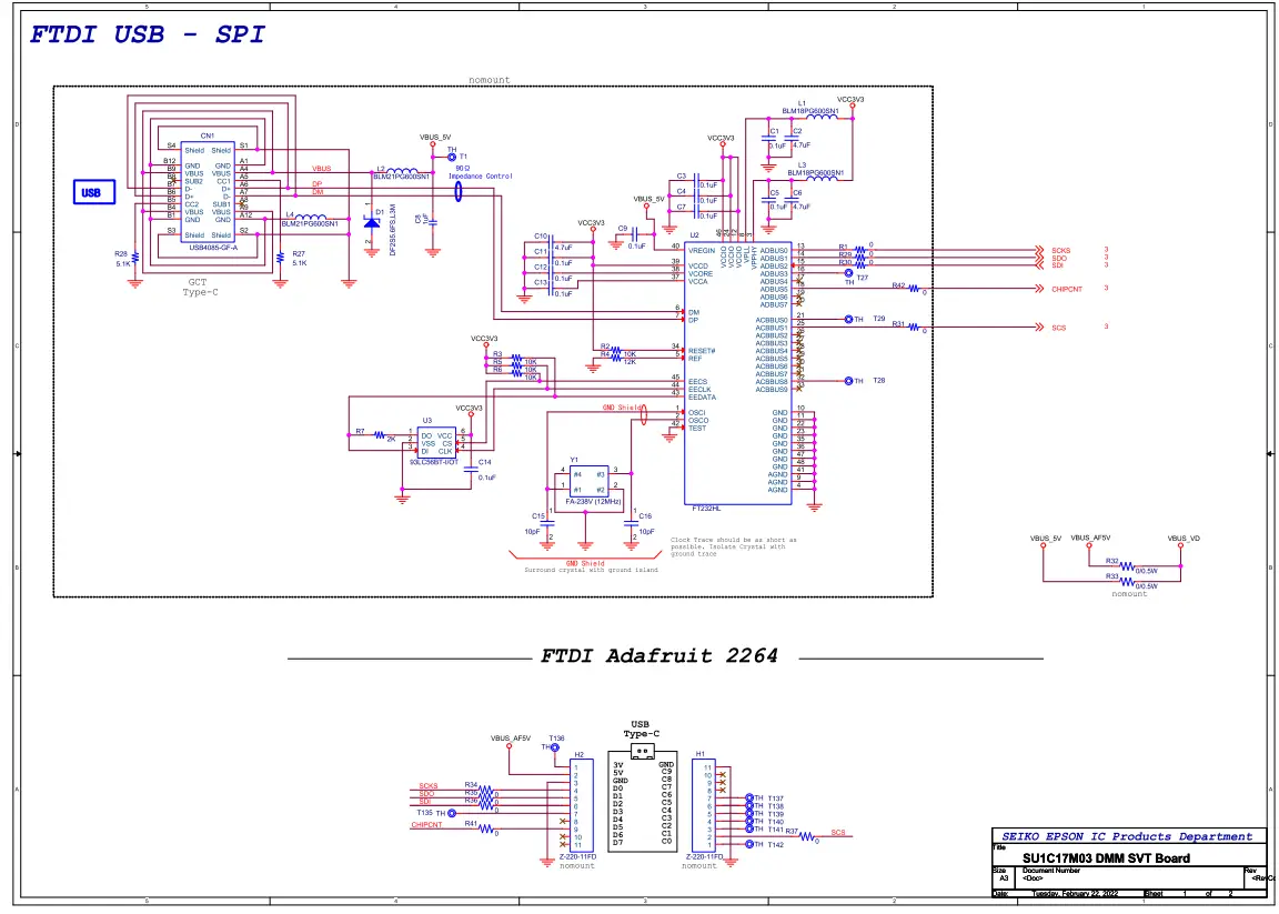
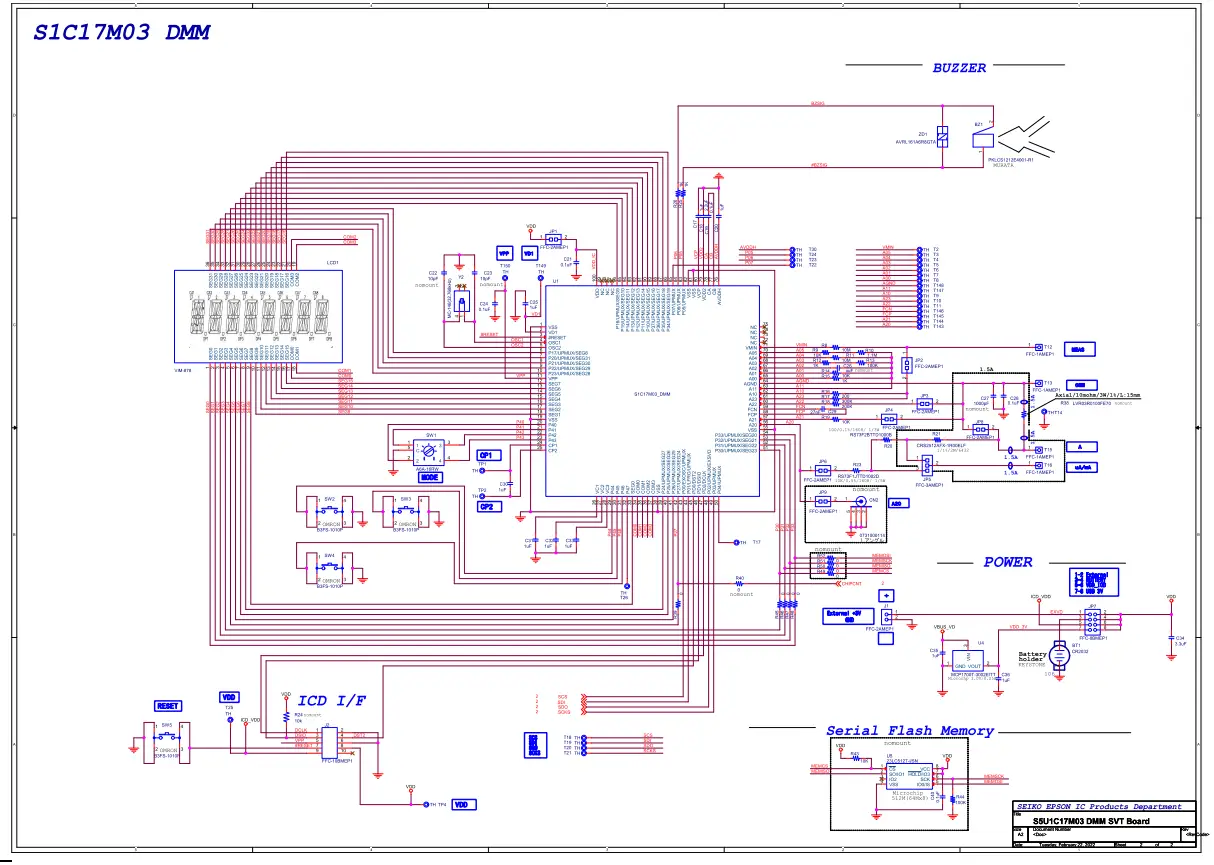
Appendix A S5U1C17M03T SVT Board schematic
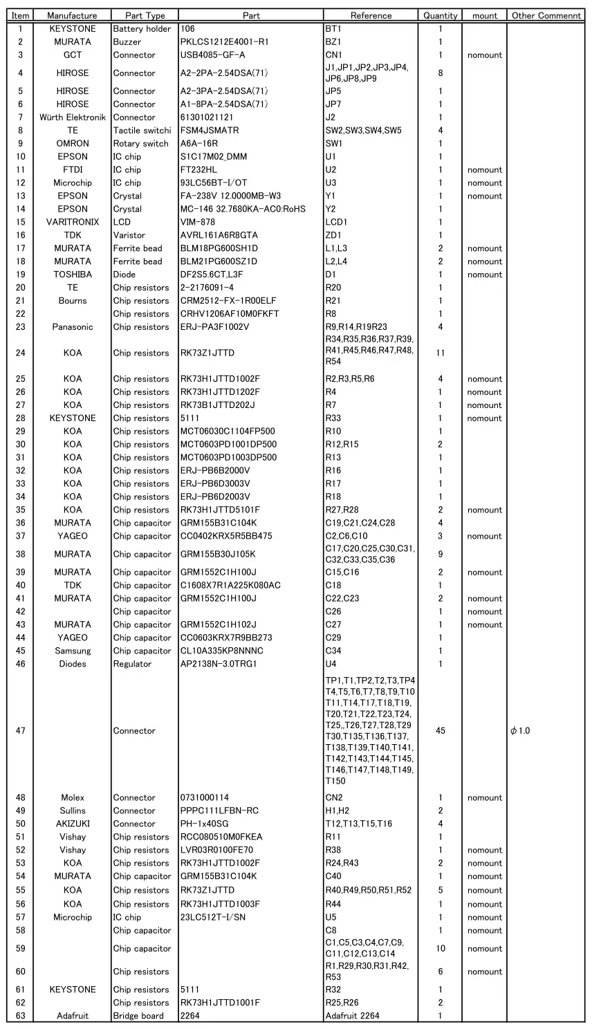
Appendix B S5U1C17M03T SVT Board Parts List
Note! Parts are subject to change without notice.
Table B.1 S5U1C17M03T SVT Board Parts List
Revision History
| Rev. No. | Date | Page | Category | Contents |
| Rev 1.0 | 2022/02/22 | All | New | New establishment |
International Sales Operations
America
Epson America, Inc.
Headquarter:
3131 Katella Ave.
Los Alamitos, CA 90720, USA
Phone: +1-800-463-7766
San Jose Office:
2860 Zanker Road Suite 204
San Jose, CA 95134, USA
Phone: +1-800-463-7766
Europe
Epson Europe Electronics GmbH
Riesstrasse 15, 80992 Munich,
Germany
Phone: +49-89-14005-0
FAX: +49-89-14005-110
Asia
Epson (China) Co., Ltd.
4th Floor, Tower 1 of China Central Place, 81 Jianguo Road, Chaoyang
District, Beijing 100025 China
Phone: +86-10-8522-1199 FAX: +86-10-8522-1120
Shanghai Branch
Room 601-603, Building A One East, No.325 East Longhua Road,
Shanghai 200023, China
Phone: +86-21-5330-4888 FAX: +86-21-5423-4677
Shenzhen Branch
Room 804-805, 8 Floor, Tower 2, Ali Center,No.3331
Keyuan South RD(Shenzhen bay), Nanshan District, Shenzhen
518054, China
Phone: +86-755-3299-0588 FAX: +86-755-3299-0560
Epson Taiwan Technology & Trading Ltd.
15F, No.100, Songren Rd, Sinyi Dist, Taipei City 110. Taiwan
Phone: +886-2-8786-6688
Epson Singapore Pte., Ltd.
438B Alexandra Road,
Block B Alexandra TechnoPark, #04-01/04, Singapore 119968
Phone: +65-6586-5500
FAX: +65-6271-7066
Epson Korea Co.,Ltd
10F Posco Tower Yeoksam, Teheranro 134 Gangnam-gu,
Seoul, 06235, Korea
Phone: +82-2-3420-6695
Seiko Epson Corp.
Sales & Marketing Division
MD Sales & Marketing Department
29th Floor, JR Shinjuku Miraina Tower, 4-1-6 Shinjuku,
Shinjuku-ku, Tokyo 160-8801, Japan
Document Code: 414282500
Issue March 2022 in JAPAN


