CAI-221 LED Dimming Table Lamp DIY Kit
ICStation LED Dimming Table Lamp DIY Kit
Introduction:
CAI-221 is a LED Dimming Table Lamp DIY Kit.
Its design inspiration comes from the desk lamp commonly used in home/office.
It uses 24 pure white LED and adjusts the brightness of the lamp through a potentiometer.
It is ideal for personal desktop lighting. It is a very interesting DIY electronic product which enables users to understand the circuit more clearly and learn soldering skills.
Feature:
1>.PWM Adjustable Brightness.
2>.Pure White LED.
3>.Flexible Lamppost.
4>.USB 5V work circuit.
Parameter:
1>.Item name: CAI-221 LED Dimming Table Lamp DIY Kit
2>.Model:CAI-221
3>.Work voltage:DC 3.7V-5V
4>.Work current:1.7A
5>.Work power:8.5W
6>.LED color temperature:6000-8000K
7>.Luminance:20-1000LUX
8>.Brightness Adjustable: 0%-100% PWM
9>.Turn ON/OFF Lamp: Yes
10>.Housing material:Metal+ABS
11>.Work Temperature:-20℃~85℃
12>.Work Humidity:5%~95%RH
13>.Size(Installed):120*90*350mm
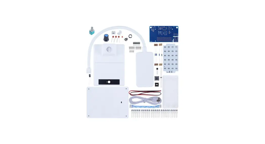
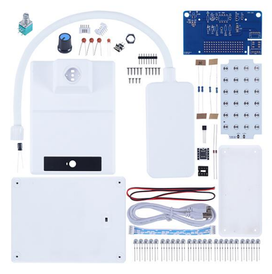
Component list:
| NO. | Component Name | PCB Marker | Parameter | QTY |
| 1 | Ceramic Capacitor | C5 | 0.001uF 102 | 1 |
| 2 | Ceramic Capacitor | C1,C3,C4 | 0.1uF 104 | 3 |
| 3 | Electrolytic Capacitor | C2 | 100uF | 1 |
| 4 | Metal Film Resistor | R1,R2 | 200ohm | 2 |
| 5 | Metal Film Resistor | R3,R4 | 10Kohm | 2 |
| 6 | IN4148 Diode | D1,D2 | DO-35 | 2 |
| 7 | ALJ2302 MOS-N | Q1 | TO-92 | 1 |
| 8 | Potentiometer | RP1 | 50Kohm | 1 |
| 9 | PH2.0-5P Socket | P2 | Bend Pin | 1 |
| 10 | PH2.0-5P Socket | P3 | Straight | 1 |
| 11 | Micro USB 2Pin | USB | SMD | 1 |
| 12 | IC Socket | U2 | DIP-8 | 1 |
| 13 | NE555 Board | U2 | 1 | |
| 14 | Male Pin | U2 | 8Pin | 1 |
| 15 | Knob Cap | 1 | ||
| 16 | PH2.0-5P Wire | 10cm | 1 | |
| 17 | 0.5W White LED | 5mm | 24 | |
| 18 | PA1.7*7 Self Tapping Screw | 10 | ||
| 19 | PA1.7*5 Self Tapping Screw | 4 | ||
| 20 | Potentiometer Nut | 1 | ||
| 21 | Red/Black Wire | 20cm | 1 | |
| 22 | USB Wire | 100cm | 1 | |
| 23 | Main PCB | 1 | ||
| 24 | LED Board | 1 | ||
| 25 | Table Lamp Case | 4 | ||
| Note:Users can complete installation according to PCB silk screen and component list. | ||||
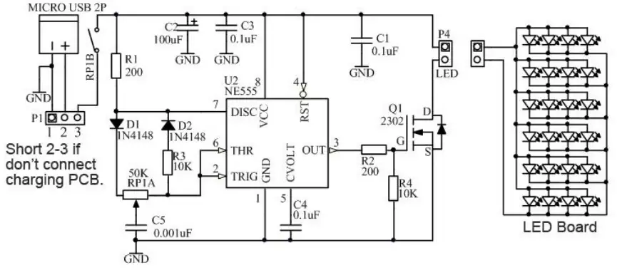
Schematic Diagram:
Installation Tips:
1>.User needs to prepare the soldering tool at first.
1.1>.Soldering iron (<50 Watt)
1.2>.Rosin core (“radio”) solder
1.3>.Wire cutters
1.4>.Wire strippers
1.5>.Philips screwdriver
2>.Please be patient until the installation is complete.
3>.The package is DIY kit.It need finish install by user.
4>.The soldering iron can’t touch components for a long time(1.0s), otherwise damage components.
5>.Pay attention to the positive and negative of the components.
6>.Strictly prohibit short circuit.
7>.Install complex components preferentially.
8>.Make sure all components are in right direction and right place.
9>.Please wear anti-static gloves or anti-static wristbands when installing electronic components.
10>.It is strongly recommended to read the installation manual before starting installation!!!
Installation Steps(Please be patient):
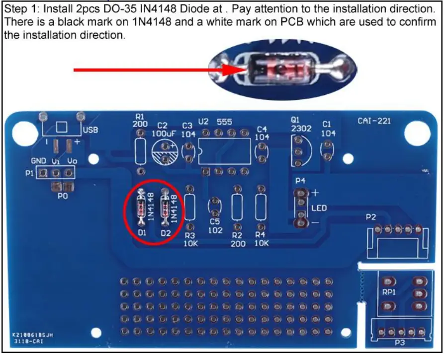
1>.Step 1: Install 2pcs DO-35 IN4148 Diode at . Pay attention to the installation direction. There is a black mark on 1N4148 and a white mark on PCB which are used to confirm the installation direction.
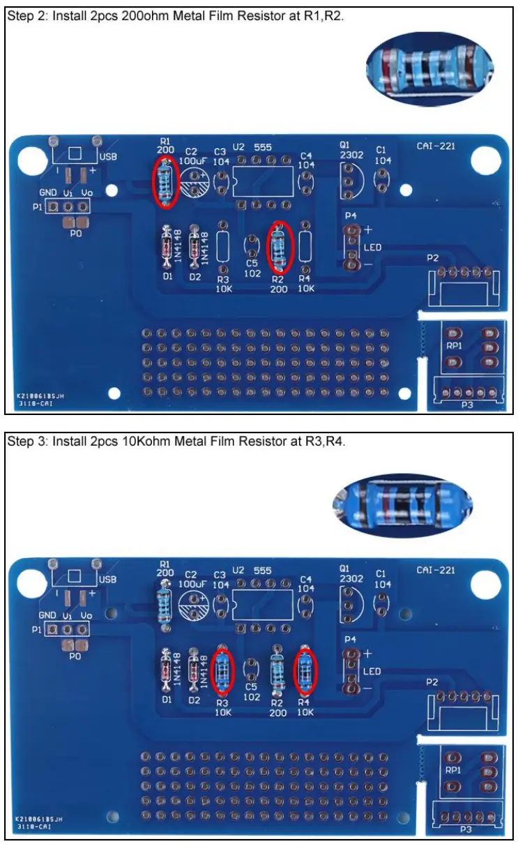
2>.Step 2: Install 2pcs 200ohm Metal Film Resistor at R1,R2.
3>.Step 3: Install 2pcs 10Kohm Metal Film Resistor at R3,R4.
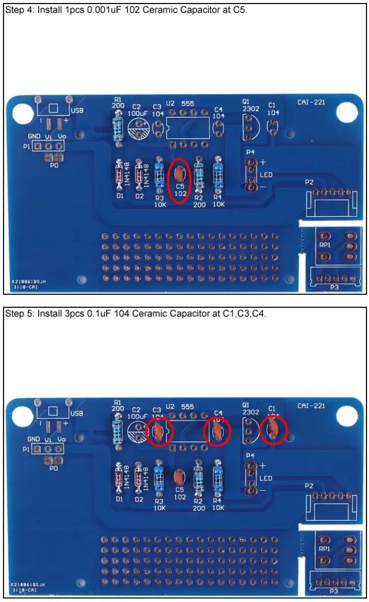
4>.Step 4: Install 1pcs 0.001uF 102 Ceramic Capacitor at C5.
5>.Step 5: Install 3pcs 0.1uF 104 Ceramic Capacitor at C1,C3,C4.
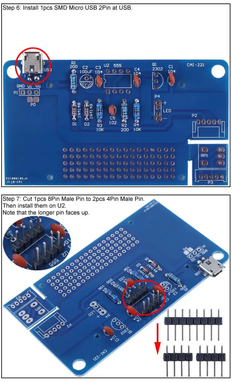
6>.Step 6: Install 1pcs SMD Micro USB 2Pin at USB.
7>.Step 7: Cut 1pcs 8Pin Male Pin to 2pcs 4Pin Male Pin. Then install them on U2. Note that the longer pin faces up.
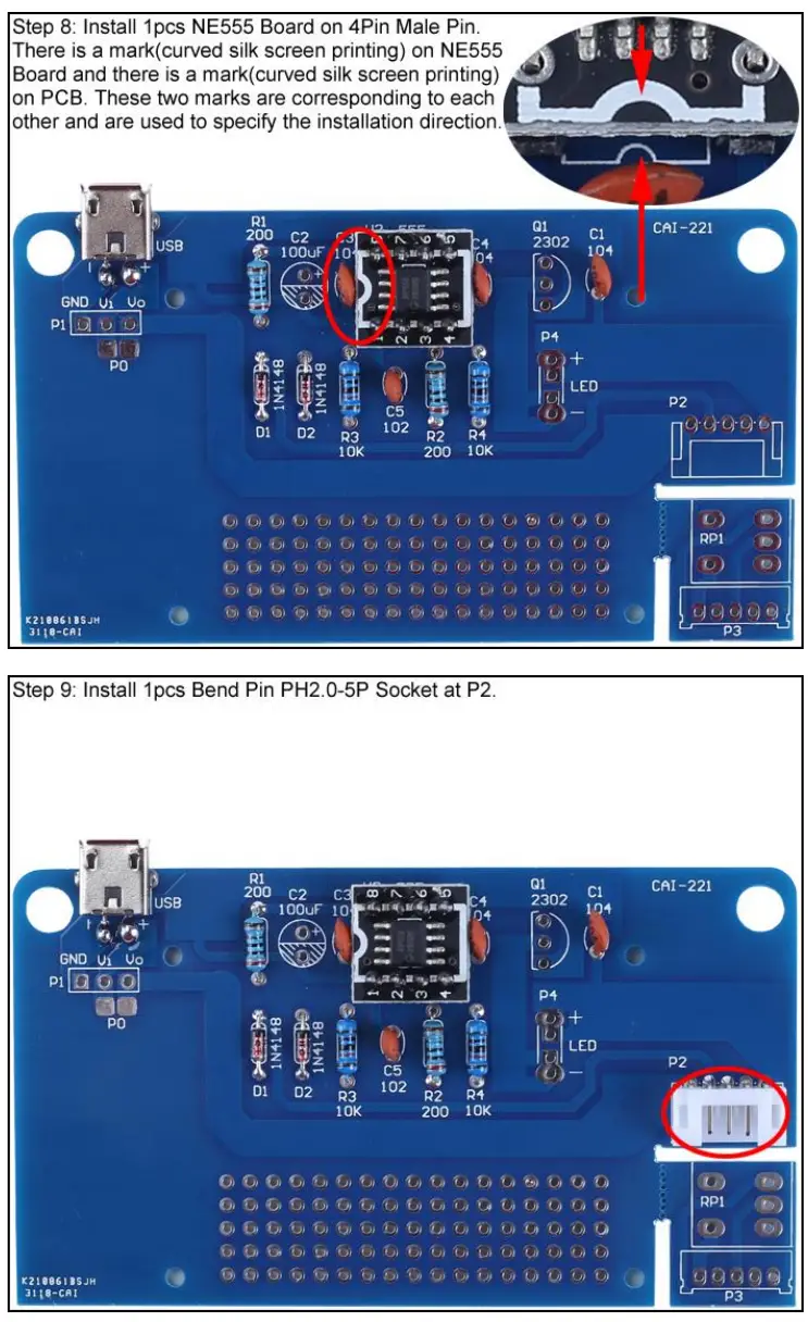
8>.Step 8: Install 1pcs NE555 Board on 4Pin Male Pin. There is a mark(curved silk screen printing) on NE555 Board and there is a mark(curved silk screen printing) on PCB. These two marks are corresponding to each other and are used to specify the installation direction.
9>.Step 9: Install 1pcs Bend Pin PH2.0-5P Socket at P2.
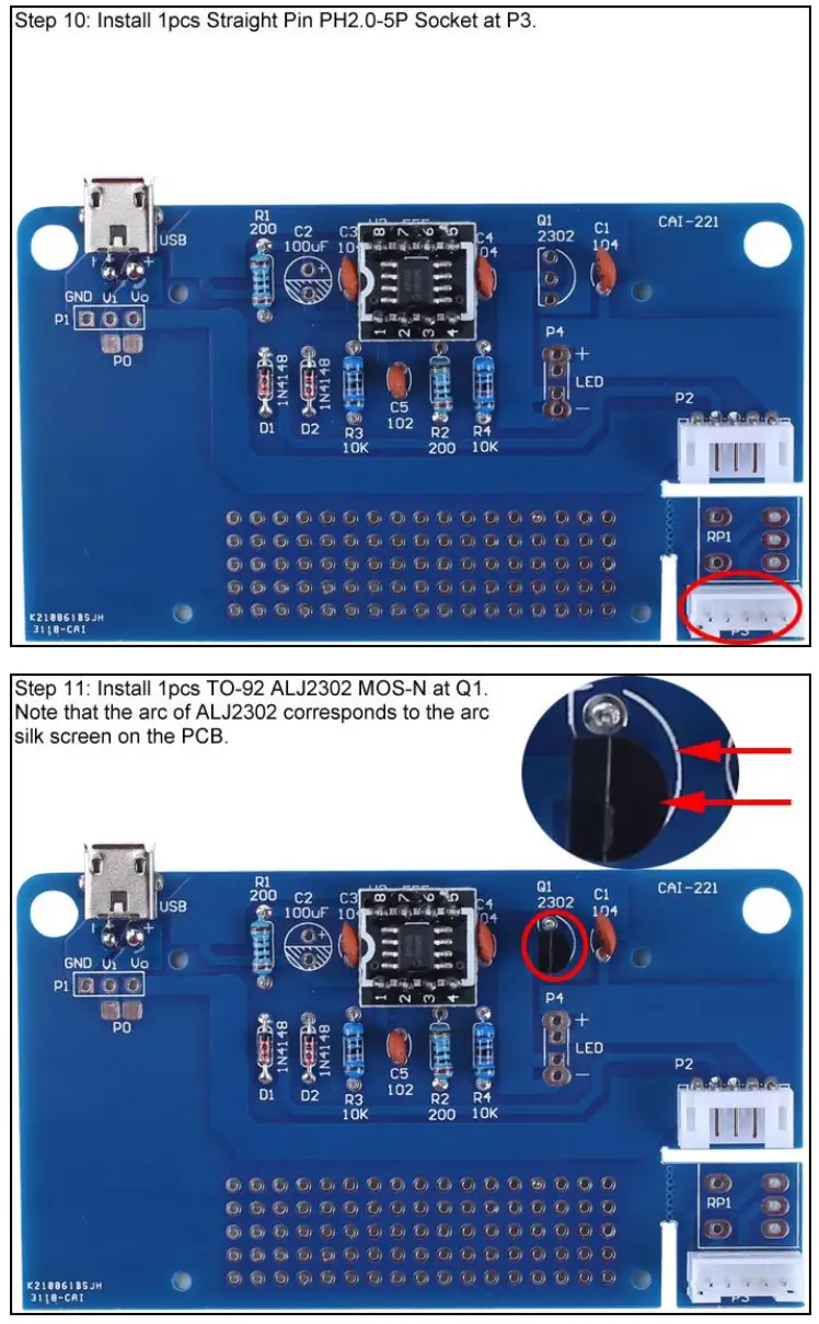
10>.Step 10: Install 1pcs Straight Pin PH2.0-5P Socket at P3.
11>.Step 11: Install 1pcs TO-92 ALJ2302 MOS-N at Q1. Note that the arc of ALJ2302 corresponds to the arc silk screen on the PCB.
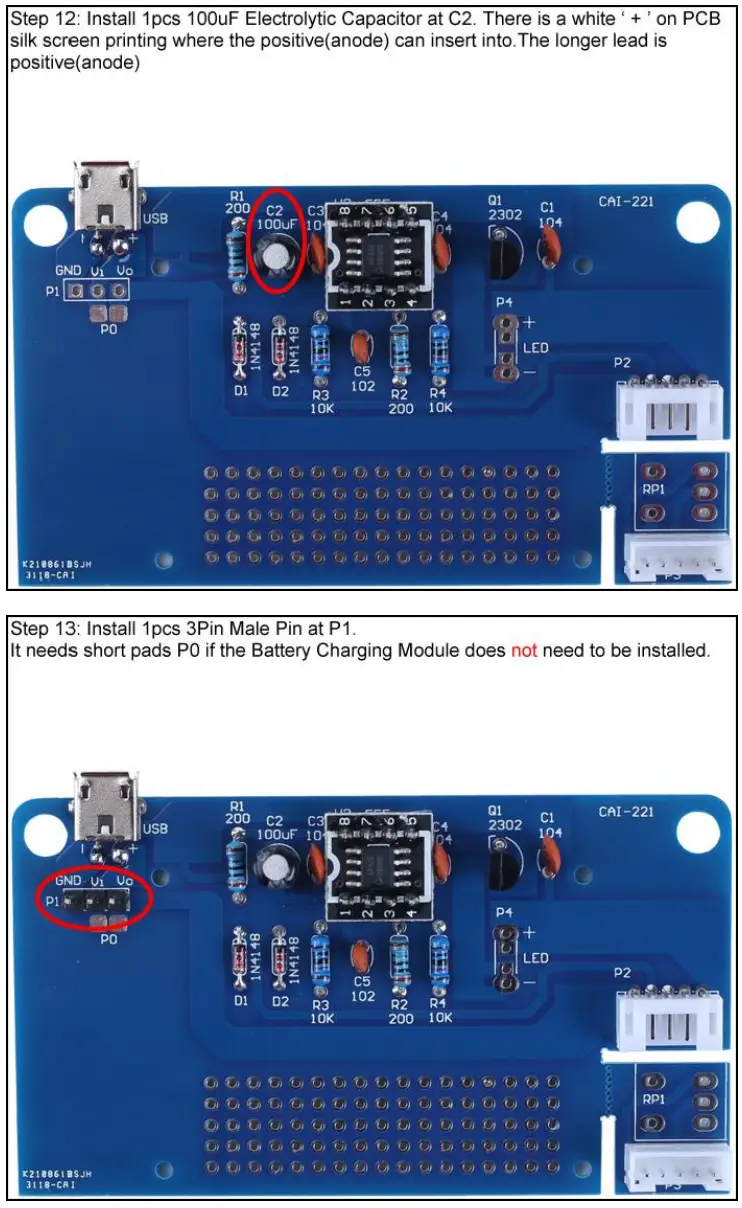
12>.Step 12: Install 1pcs 100uF Electrolytic Capacitor at C2. There is a white ‘ + ’ on PCB silk screen printing where the positive(anode) can insert into.The longer lead is positive(anode)
13>.Step 13: Install 1pcs 3Pin Male Pin at P1. It needs short pads P0.
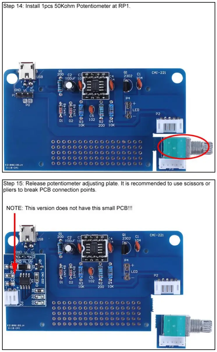
14>.Step 14: Install 1pcs 50Kohm Potentiometer at RP1.
15>.Step 15: Release potentiometer adjusting plate. It is recommended to use scissors or pliers to break PCB connection points.
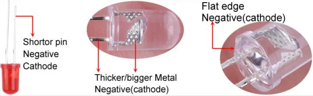
16>.Step 16: Identify the positive(anode) and negative(cathode) lead of LED.The leads of the LED must be installed correctly, otherwise the LED cannot be turned on.Here are four methods as following:
16.1>.According to the length of the LED lead to distinguish. The longer pin is positive(anode) lead.
The shorter pin is negative(cathode) lead.
16.2>.Identify the negative(cathode) of the LED is to look into the plastic case where one can see that the negative(cathode) is much thicker/bigger inside the plastic case than the anode lead.
16.3>.Identify by edge of plastic case.The negative(cathode) lead of the LED should be the pin nearest the flat on the plastic case.
16.4>.Test by 3V battery or multi-meter.The pin is positive(anode) lead which has connect to the positive of 3V if LED can light up after connect 3V power supply.(LED should not be powered directly from the 3V for a short time:less then 0.5second)
16.5>.It is positive(anode) where the white mark “ + ” pointing to on PCB.
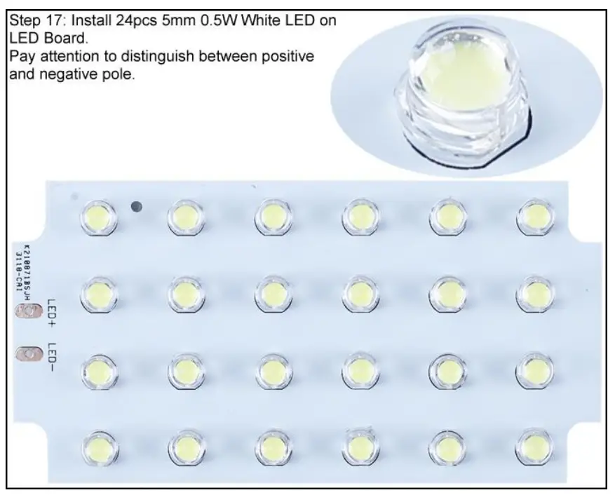
17>.Step 17: Install 24pcs 5mm 0.5W White LED on LED Board. Pay attention to distinguish between positive and negative pole.
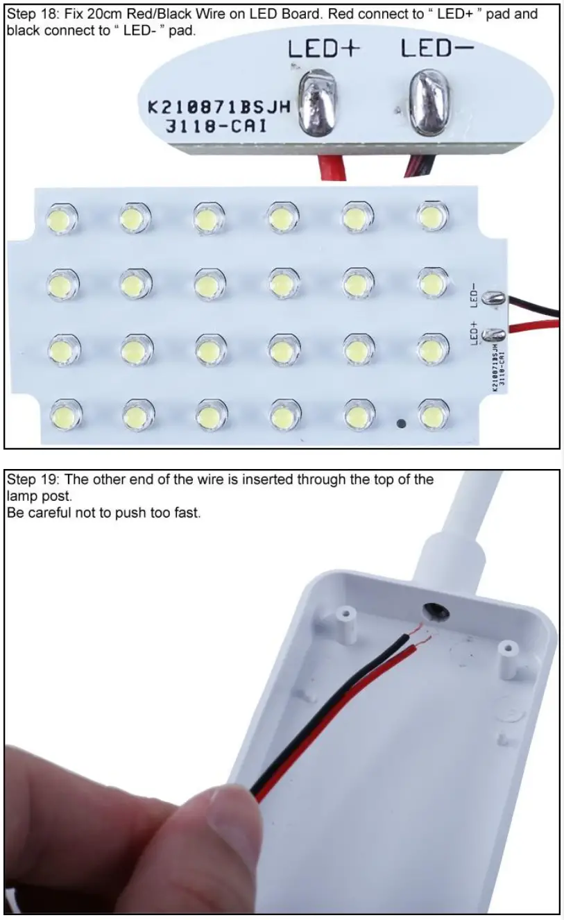
18>.Step 18: Fix 20cm Red/Black Wire on LED Board. Red connect to “ LED+ ” pad and black connect to “ LED- ” pad.
19>.Step 19: The other end of the wire is inserted through the top of the lamp post.Be careful not to push too fast.
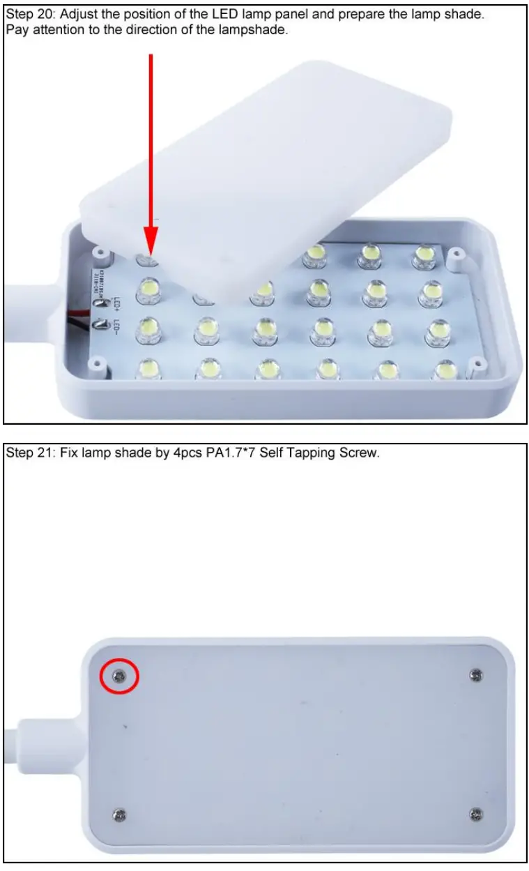
20>.Step 20: Adjust the position of the LED lamp panel and prepare the lamp shade.Pay attention to the direction of the lampshade.
21>.Step 21: Fix lamp shade by 4pcs PA1.7*7 Self Tapping Screw.
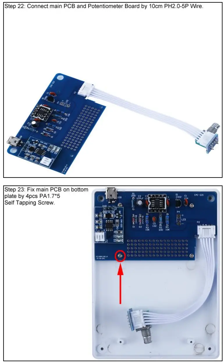
22>.Step 22: Connect main PCB and Potentiometer Board by 10cm PH2.0-5P Wire.
23>.Step 23: Fix main PCB on bottom plate by 4pcs PA1.7*5 Self Tapping Screw.
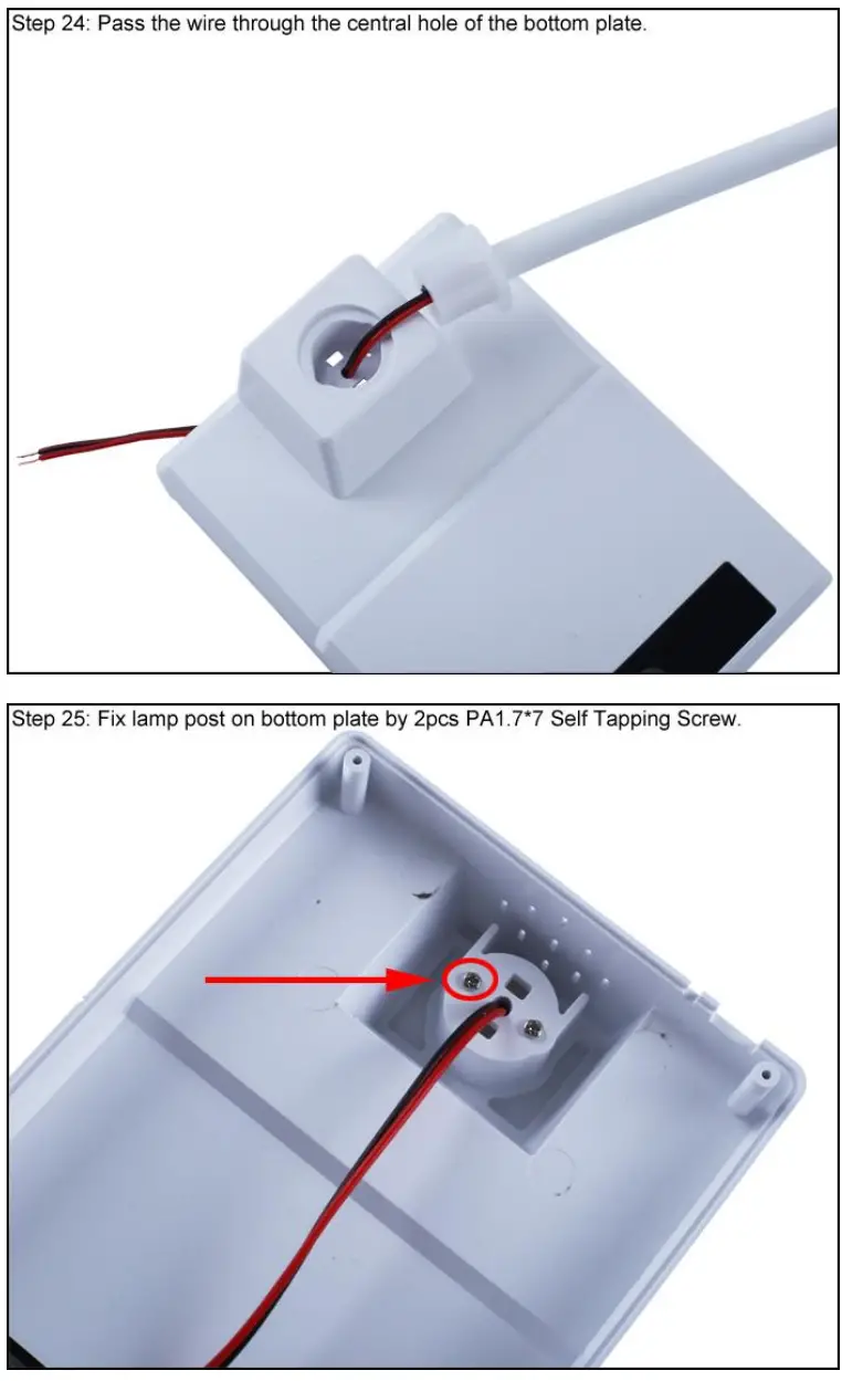
24>.Step 24: Pass the wire through the central hole of the bottom plate.
25>.Step 25: Fix lamp post on bottom plate by 2pcs PA1.7*7 Self Tapping Screw.
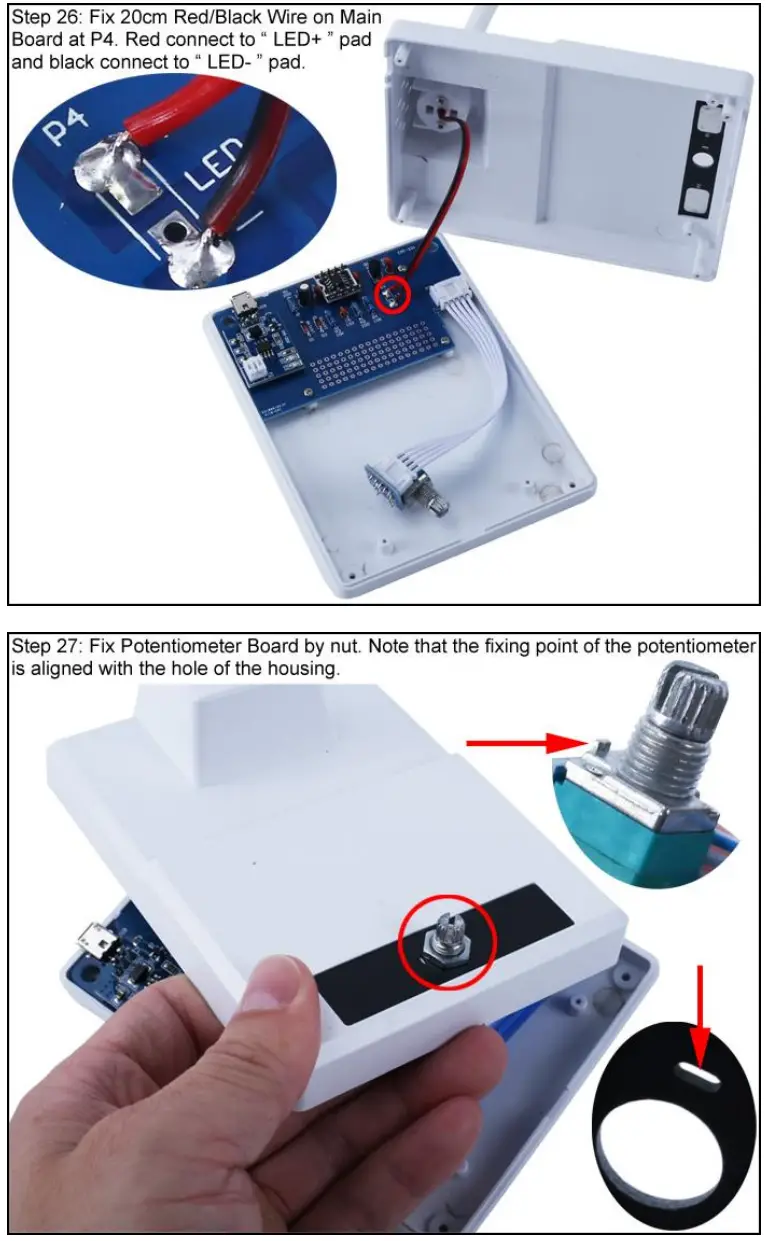
26>.Step 26: Fix 20cm Red/Black Wire on Main Board at P4. Red connect to “ LED+ ” pad and black connect to “ LED- ” pad.
27>.Step 27: Fix Potentiometer Board by nut. Note that the fixing point of the potentiometer is aligned with the hole of the housing.
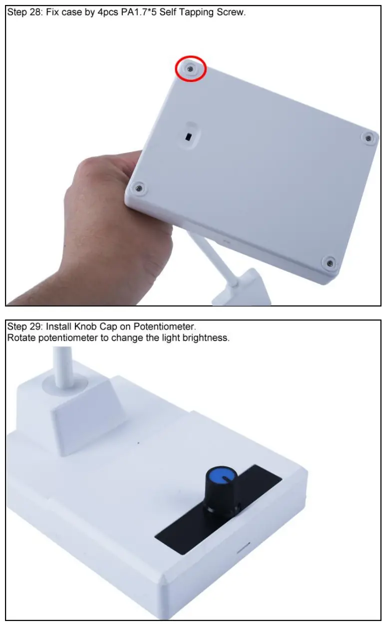
28>.Step 28: Fix case by 4pcs PA1.7*5 Self Tapping Screw.
29>.Step 29: Install Knob Cap on Potentiometer. Rotate potentiometer to change the light brightness.
Install shown steps:
Step 16: Identify the positive(anode) and negative(cathode) lead of LED.The leads of the LED must be installed correctly, otherwise the LED cannot be turned on.Here are four methods as following:
16.1>.According to the length of the LED lead to distinguish. The longer pin is positive(anode) lead. The shorter pin is negative(cathode) lead.
16.2>.Identify the negative(cathode) of the LED is to look into the plastic case where one can see that the negative(cathode) is much thicker/bigger inside the plastic case than the anode lead.
16.3>.Identify by edge of plastic case.The negative(cathode) lead of the LED should be the pin nearest the flat on the plastic case.
16.4>.Test by 3V battery or multimeter.The pin is positive(anode) lead which has connect to positive of 3V if LED can light up after connect 3V power supply. (LED can not be powered directly from 3V for a short time:less then 0.5second)
16.5>.Note:lf the flat on package disagrees with other indicators(short lead,large cathode lead end), then other indicators take priority. I.e. if the flat disagrees with the lead length.use the lead length as the cathode indicator.
CAI-221 LED Dimming Table Lamp DIY Kit


