
Poulan pro PP19A42 LAWN TRACTOR

REPAIR PARTS
TRACTOR – MODEL NUMBER PP19A42 (96046007700), PRODUCT NO. 960 46 00-77 SCHEMATIC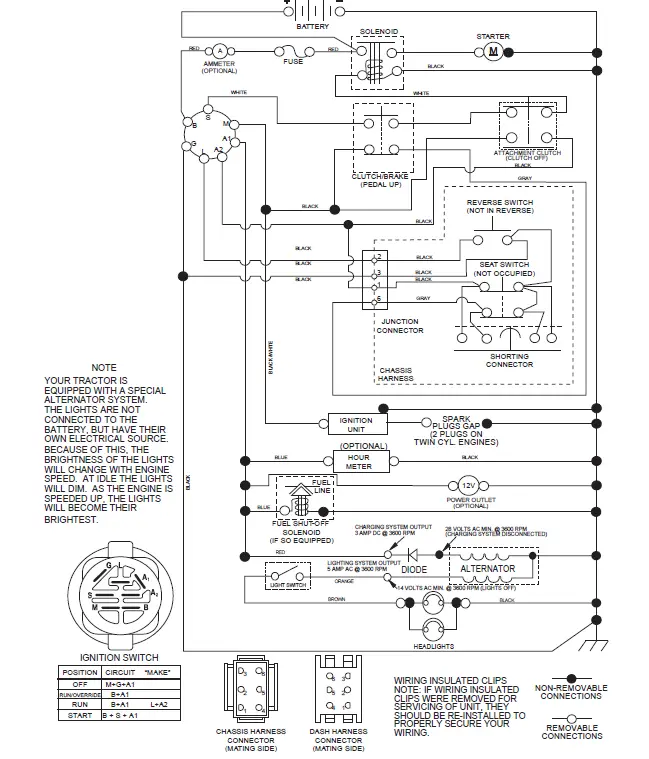
TRACTOR – MODEL NUMBER PP19A42 (96046007700), PRODUCT NO. 960 46 00-77 ELECTRICAL 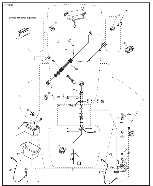
| KEY | PART | |
| NO. | NO. | DESCRIPTION |
| 1 | 532 14 49-25 | Battery |
| 2 | 874 76 04-12 | Bolt Hex Hd 1/4-20 unc x 3/4 |
| 8 | 532 19 32-28 | Box Battery |
| 16 | 532 17 61-38 | Switch Interlock |
| 21 | 532 40 02-52 | Harness Asm Light w/4152j |
| 22 | 532 00 41-52 | Bulb Light #1156 |
| 25 | 581 49 80-01 | Cable Starter |
| 26 | 532 17 51-58 | Fuse 20 AMP |
| 27 | 873 51 04-00 | Nut Keps Hex 1/4-20 unc |
| 28 | 532 42 16-86 | Cable Ground 6 Ga. 12″ Black |
| 29 | 532 19 27-49 | Switch Seat |
| 30 | 532 19 33-50 | Switch Ign |
| 33 | 532 41 19-33 | Key/Chain |
| 34 | 532 11 07-12 | Switch Light/Reset |
| 40 | 581 02 31-01 | Harness Ign Dash |
| 43 | 532 19 25-07 | Solenoid |
| 55 | 817 06 05-12 | Screw 5/16-18 x 3/4 |
| 71 | 581 02 30-01 | Harness Chassis |
| 79 | 532 17 52-42 | Socket Asm. Bulb Twistlock |
| 87 | 532 19 78-02 | Switch Interlock |
| 90 | 532 43 53-95 | Cover Terminal Battery |
| 99 | 817 67 04-12 | Screw Hexwsh Thdrol 1/4-20 x 3/4 |
| 102 | 581 02 34-01 | Harness Pigtail |
| 105 | 532 40 75-68 | Switch Reverse |
| 106 | 532 17 48-14 | Palnut 1/4 Lugs |
NOTE: All component dimensions given in U.S. inches 1 inch = 25.4 mm.
| KEY | PART | |
| NO. | NO. | DESCRIPTION |
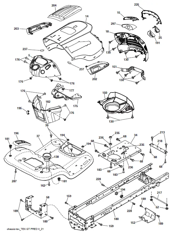
| 5 | 532 44 18-82 | Dash |
| 14 | 501 12 85-01 | Hood |
| 15 | 581 10 31-01 | Lens LH |
| 18 | 581 10 29-02 | Grille |
| 25 | 581 10 30-01 | Lens RH |
| 34 | 580 91 08-01 | Plate Engine |
| 36 | 817 06 05-12 | Screw 5/16-18 x 3/4 |
| 37 | 532 42 07-96 | Fender |
| 52 | 873 68 05-00 | Nut Lock 5/16-18 |
| 58 | 532 41 22-80 | Drawbar Upper |
| 68 | 817 49 05-08 | Screw Thdrol 5/16-18 x 1/2 |
| 130 | 532 41 63-58 | Screw #10 x 0.750 |
| 138 | 532 40 97-30 | Cupholder |
| 150 | 584 86 29-03 | Duct Heat Hood |
| 151 | 532 44 54-94 | Bracket Pivot |
| 152 | 532 19 95-35 | Shield Browning |
| 159 | 817 00 06-12 | Screw Hexwsh Thdrol 3/8-16 x 3/4 |
| 162 | 532 14 24-32 | Screw Hex Wsh Hi-Lo 1/4 x 1/2 |
| 175 | 532 19 63-04 | Crossmember |
| 176 | 532 40 07-76 | Screw 10-24 x 5/8 Wshd Qdrx |
| 177 | 532 19 52-28 | Bushing Steering |
| 180 | 532 41 50-63 | Chassis |
| 181 | 532 40 47-96 | Bushing Mtg. Fender Crgo. |
| 182 | 586 73 86-02 | Dash Lower |
| 183 | 874 52 05-20 | Bolt 5/16-18 x 1-1/4 |
| 189 | 817 00 05-12 | Screw 5/16-18 x 3/4 |
| 191 | 581 22 35-01 | Insert Reflector RH |
| 194 | 873 90 05-00 | Nut Lock Hex Flange 5/16-18 |
| 195 | 532 40 41-37 | Plug Hole Dash Lower |
| 196 | 532 41 45-81 | Console Asm. Deck Lift |
| 202 | 501 51 01-01 | Vent Side Hood RH |
| 203 | 501 51 01-02 | Vent Side Hood LH |
| 204 | 587 96 32-01 | Vent Asm. Top |
| 213 | 874 76 05-12 | Bolt 5/16-18 x 3/4 |
| 217 | 532 40 91-67 | Rod Pivot Hood |
| 218 | 532 19 63-95 | X-Piece Hood Step |
| 225 | 581 10 32-01 | Trim Ring |
| 228 | 532 19 51-61 | Stud Fastener |
| 235 | 532 40 61-29 | Spacer Fender |
| 236 | 873 93 05-00 | Nut Center Lock 5/16-18 |
| 237 | 532 40 37-04 | Plug Mount Cargo |
| 287 | 817 60 04-06 | Screw 1/4-20 x 3/8 |
| 297 | 581 22 36-01 | Insert Reflector LH |
| – – | 532 44 11-26 | Plug Dash Srvmndr |
| KEY | PART | KEY | PART | ||
| NO. | NO. | DESCRIPTION | NO. | NO. | DESCRIPTION |
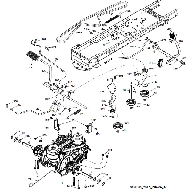
| 1 | – – – – – – | Transaxle, Variator SD Pedal | 186 | 532 19 43-21 | Spacer Retainer |
| (580486201) (Order parts from | 187 | 819 13 32-10 | Washer 13/32 x 2 x 10 ga | ||
| transaxle manufacturer.) | 188 | 532 19 43-23 | Link Clutch Ground Drive | ||
| 2 | 532 12 35-83 | Key Square | 189 | 532 19 43-17 | Bellcrank Ground Drive |
| 5 | 874 76 06-36 | Bolt Hex Hs 3/8-16 unc x 2-1/4 | 190 | 532 19 43-18 | Keeper. Bellcrank |
| 6 | 532 12 40-28 | Bushing Snap | 195 | 581 50 46-01 | Bracket Brake |
| 15 | 819 13 13-16 | Washer 13/32 x 13/16 x 16 Ga. | 203 | 819 11 11-16 | Washer 11/32 x 11/16 x 16 Ga. |
| 17 | 584 95 40-01 | Spring, Brake | 205 | 532 12 17-48 | Washer 25/32 x 1-5/8 16 Ga. |
| 29 | 584 82 31-01 | Rod, Brake | 210 | 532 44 82-70 | Rocker Asm. Pedal |
| 33 | 812 00 00-01 | Ring E | 214 | 532 42 12-63 | Pedal Forward |
| 35 | 583 86 45-01 | Rod, Brake, Park | 215 | 532 44 82-54 | Pad Pedal Reverse |
| 37 | 532 18 89-67 | Washer .793 x 1.637 x 060 | 211 | 532 12 01-83 | Bearing Nylon |
| 42 | 532 12 48-72 | Cover, Foot Pedal | 221 | 532 40 31-87 | Retainer Spring |
| 49 | 872 11 06-14 | Bolt 3/8-16 unc | 222 | 879 21 20-10 | Washer Flat |
| 50 | 532 19 43-27 | Idler Flat | 277 | 532 44 85-00 | Subasm. Link Rocker Pedal |
| 51 | 873 90 06-00 | Nut Lock 3/8-16 unc | 282 | 874 49 05-48 | Screw Thdrol 5/16-18 x 3 |
| 52 | 532 19 43-26 | Idler V-Groove | 299 | 532 41 56-83 | Bracket Mount |
| 56 | 532 19 72-53 | V-Belt, Drive | 300 | 532 41 56-81 | Keeper Idler |
| 64 | 532 44 83-53 | Subasm. Shaft Pedal Brake | 301 | 532 41 56-80 | Pulley Idler Groove |
| 67 | 819 13 13-12 | Washer 13/32 x 13/16 x 12 Ga. | 302 | 581 42 05-01 | Puller Idler Flat |
| 73 | 874 49 05-44 | Bolt Hex 5/16-18 x 3.75 | 303 | 872 11 06-18 | Bolt |
| 99 | 532 43 59-35 | Rod Bypass | 306 | 876 02 04-16 | Pin Cotter 1/8 x 1 |
| 116 | 873 90 05-00 | Nut Lock Hex Flange 5/16-18 | 345 | 872 11 06-06 | Bolt 3/8-16 unc |
| 125 | 817 00 05-12 | Screw 5/16-18 x 3/4 | 373 | 581 46 18-01 | Spacer Idler |
| 143 | 817 49 05-08 | Screw Thdrol 5/16-18 x 1/2 TYTT | 374 | 581 47 52-01 | Arm Control Brake |
| 159 | 876 02 04-12 | Pin Cotter 1/8 x 3/4 | 375 | 873 68 06-00 | Nut Crownlock 3/8-16 unc |
| 160 | 532 16 94-84 | Retainer Clip | 378 | 584 28 77-01 | Nut Push 8 mm |
| 161 | 532 10 57-09 | Spring, Return, Clutch | |||
| 163 | 587 84 79-01 | Rod Control | |||
| 166 | 532 42 91-64 | Nut Push .625 | |||
| 167 | 532 40 52-57 | Latch Brake Parking | |||
| 172 | 583 97 42-01 | Strap Torque | |||
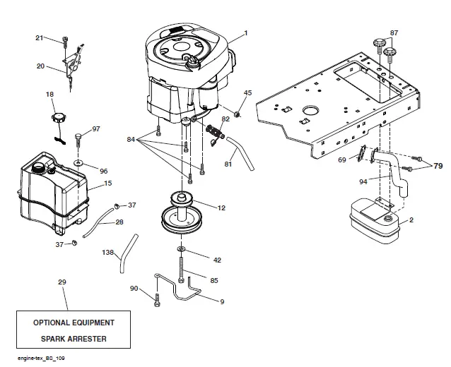
| 2 | 580 53 23-01 | Muffler Exhaust B&S |
| 9 | 584 91 16-01 | Keeper Belt Engine |
| 12 | 586 72 90-01 | Pulley Engine |
| 15 | 532 43 30-07 | Tank Fuel Front |
| 18 | 581 17 61-01 | Cap Asm Fuel |
| 20 | 532 18 38-97 | Control Th/Ch |
| 21 | 532 41 63-58 | Screw #10 x 0.750 |
| 28 | 532 40 11-37 | Line Fuel |
| 29 | 532 13 71-80 | Kit Spark Arrestor (Flat Scrn) |
| 37 | 532 12 34-87 | Clamp Hose |
| 42 | 810 04 07-00 | Washer Lock Hvy Hlcl Spr 7/16 |
| 45 | 873 51 04-00 | Nut Keps Hex 1/4-20 unc |
| 69 | 532 16 52-91 | Gasket Eng 1 313 Id Tin Plated |
| 79 | 532 19 23-34 | Screw Socket Head 5/16-18 x 3/4 |
| 81 | 532 14 84-56 | Tube Drain Oil Easy |
| 82 | 532 42 82-87 | Valve Oil Drain |
| 84 | 817 06 06-20 | Screw 3/8-16 x 1-1/4 |
| 85 | 532 17 39-37 | Bolt Hex 7/16-20 x 4 x Gr 5-1.5 Thr. |
| 87 | 532 17 18-77 | Bolt 5/16-18 unc x 3/4 w/Sems |
| 90 | 817 00 06-16 | Screw 3/8-16 x 1 |
| 94 | 581 88 09-01 | Exhaust Tube |
| 96 | 819 09 14-16 | Washer 9/32 x 7/8 x 16 Ga. |
| 97 | 817 67 04-12 | Screw Thdrol 1/4-20 x 3/4 |
| 138 | 532 41 41-19 | Purge Line |
NOTE: All component dimensions given in U.S. inches 1 inch = 25.4 mm
For engine service and replacement parts, call the toll-free number for your engine manufacturer listed below: Briggs & Stratton 1-800-233-3723
Engine Power Rating Information
The gross power rating for individual gas engine models is labeled in accordance with SAE (Society of Automotive Engineers) code J1940 (Small Engine Power & Torque Rating Procedure), and rating performance has been obtained and corrected in accordance with SAE J1995 (Revision 2002-05). Torque values are derived at 3060 RPM; horsepower values are derived at 3600 RPM. Actual gross engine power will be lower and is affected by, among other things, ambient operating conditions and engine-to-engine variability. Given both the wide array of products on which engines are placed and the variety of environmental issues applicable to operating the equipment, the gas engine will not develop the rated gross power when used in a given piece of power equipment (actual “on-site” or net power). This difference is due to a variety of factors including, but not limited to, accessories (air cleaner, exhaust, charging, cooling, carburetor, fuel pump, etc.), application limitations, ambient operating conditions (temperature, humidity, altitude), and engine-to-engine variability. Due to manufacturing and capacity limitations, Briggs & Stratton may substitute an engine of higher-rated power for this Series engine.
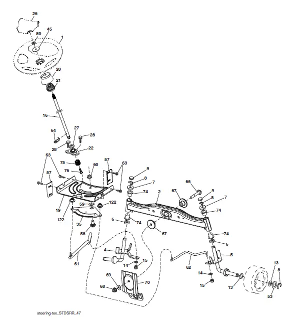
| KEY | PART | |
| NO. | NO. | DESCRIPTION |
| 1 | 532 42 45-43 | Wheel, Steering |
| 2 | 532 41 81-68 | Axle Asm., Front |
| 4 | 532 40 30-87 | Spindle Asm., LH |
| 5 | 532 40 30-88 | Spindle Asm., RH |
| 6 | 532 12 49-31 | Washer Thrust 0.75 x 1.23 |
| 7 | 532 12 17-48 | Washer 25/32 x 1-5/8 x 16 Ga. |
| 8 | 812 00 00-29 | Ring, Clip #T5304-75 |
| 9 | 532 12 12-32 | Cap, Spindle |
| 13 | 532 12 17-49 | Washer 25/32 x 1-1/4 x 16 Ga. |
| 14 | 810 04 06-00 | Washer Lock 3/8 |
| 15 | 873 54 06-00 | Nut, Crown Lock 3/8-24 unf |
| 16 | 587 01 60-01 | Shaft Steering |
| 19 | 532 19 47-29 | Plate Steering |
| 20 | 532 42 47-40 | Boot, Steering |
| 21 | 586 84 02-01 | Adapter, Wheel Steering |
| 22 | 585 02 98-02 | Bearing Subasm Shaft Steer Low |
| 26 | 532 42 46-91 | Insert, Wheel Steering |
| 27 | 819 21 16-16 | Washer 21/32 x 1 x 16 Ga. |
| 28 | 817 00 06-12 | Screw 3/8-16 x 3/4 |
| 35 | 532 19 47-32 | Gear, Sector Plate |
| 45 | 587 01 64-01 | Washer 3/8 ID x 2-3/8 OD 12 Ga. |
| 50 | 873 90 06-00 | Nut Lock Flg. 3/8-16 unc |
| 53 | 532 18 89-67 | Washer Hardened .793 x 1.637 x .060 |
| 57 | 532 40 74-65 | Bracket Upstop |
| 58 | 532 19 47-47 | Bolt Shoulder Sector Pivot CFM |
| 59 | 532 19 47-48 | Washer Thrust Sector Steering |
| 60 | 873 97 10-00 | Nut Flange Lock 5/8-11 |
| 61 | 532 19 47-40 | Draglink, LH |
| 62 | 532 19 47-41 | Draglink, RH |
| 63 | 817 00 05-12 | Screw 5/16-18 x 3/4 |
| 64 | 532 19 98-49 | Retainer Clip Spring Steering |
| 66 | 871 02 07-48 | Bolt Hex Fghd 7/16-14 x 3 Serr |
| 67 | 532 19 47-37 | Bushing PM Front Axle |
| 68 | 873 90 07-00 | Nut Lock Flange 7/16-14 Gr. 5 |
| 69 | 532 19 91-62 | Washer 1.5 x .505 x .118 |
| 70 | 585 33 88-01 | Bracket Deck Susp. Front |
| 74 | 532 12 49-37 | Bearing |
| 75 | 580 68 37-01 | Pinion |
| 76 | 580 68 36-01 | Screw Head Sock |
| 122 | 532 44 49-62 | Cap Gear |
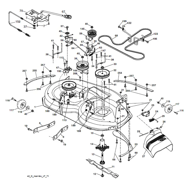
| KEY | PART | KEY | PART | ||
| NO. | NO. | DESCRIPTION | NO. | NO. | DESCRIPTION |
| 1 | 532 42 46-96 | Mower Housing | 59 | 532 14 10-43 | Guard, Tuv Idler (94) |
| 6 | 532 19 51-86 | Arm Suspension | 60 | 532 19 72-61 | Arm Brake Mower |
| 7 | 532 41 63-58 | Screw #10 x 0.750 BOS Thread | 62 | 872 11 06-16 | Bolt Rdhd Sqnk 3/8-16 unc x 2 |
| 11 | 532 13 89-71 | Blade, 42″ Hi-Lift | 63 | 532 19 94-77 | Arm Brake Mower |
| (For bagging or discharge) 64 532 19 99-18 Linkage Brake | |||||
| – – | 532 13 97-75 | Blade, 42″ Mulching Premium | 67 | 532 40 30-12 | Handle, Clutch Cable |
| (For better wear when mulching) 68 532 42 96-36 V-Belt | |||||
| – – | 532 13 41-49 | Blade, 42″ Mulching Std | 69 | 872 14 05-05 | Bolt Rdhd Sqnk 5/16-18 x 5/8 |
| (For mulching mowers only) 70 532 19 99-72 Clutch Asm. Manual | |||||
| – – | 532 42 47-52 | Blade 42SP” 3N1 | 113 | 817 00 05-10 | Screw 5/16-18 |
| – – | 532 42 27-19 | Blade 42SP” Premium | 116 | 532 12 48-42 | Bolt Shoulder |
| 12 | 584 30 93-01 | Screw Sems 7/16-20 x 1 Hx Hd | 117 | 532 18 86-06 | Wheel Gauge |
| 13 | 532 19 28-72 | Shaft Assembly, Mandrel | 119 | 819 12 14-14 | Washer 3/8 x 7/8 x 14 Ga. |
| 14 | 532 18 72-81 | Housing, Mandrel | 122 | 532 19 72-58 | Keeper Belt Eng. LH |
| 15 | 532 11 04-85 | Bearing, Ball, Mandrel | 123 | 532 19 72-59 | Keeper Belt Eng. RH |
| 19 | 532 19 65-39 | Bolt, Shoulder | 144 | 532 19 92-04 | Keeper Belt |
| 20 | 532 15 97-70 | Baffle, Vortex | 145 | 532 19 31-97 | Pulley Idler Primary |
| 21 | 873 68 05-00 | Nut, Crownlock 5/16-18 unc | 147 | 532 40 19-71 | Spring Return |
| 23 | 532 19 25-57 | Bracket, Deflector | 152 | 584 24 35-01 | Cable Clutch Manual |
| 24 | 532 10 53-04 | Cap, Sleeve | 188 | 532 19 51-61 | Stud Fastener |
| 25 | 532 19 70-26 | Spring, Torsion, Deflector | 189 | 873 90 05-00 | Nut Lock Hex Flange |
| 26 | 532 11 04-52 | Nut, Push | 192 | 532 19 72-60 | Bracket Brake Stand LH |
| 27 | 532 40 30-04 | Shield, Deflector | 195 | 817 00 06-12 | Screw Hexwsh Thdr 3/8-16 x 3/4 |
| 29 | 532 13 14-91 | Rod, Hinge | 208 | 817 67 06-08 | Screw THDROL 3/8-16 x 1/2 |
| 32 | 532 19 74-73 | Pulley, Mandrel | 254 | 585 31 68-05 | Plate Reinforcement Front |
| 33 | 532 40 02-34 | Nut, Toplock, Flanged | 255 | 585 31 70-05 | Plate Reinforcement Side |
| 34 | 872 11 06-12 | Bolt Carr Sh. 3/8-16 x 1-1/2 Gr. 5 | 256 | 539 10 98-00 | Carriage Bolt 1/4-20 x 1 Gr. 5 |
| 36 | 532 19 73-79 | Pulley, Idler 4.50 RAW | 257 | 873 90 04-00 | Nut Hex Flg 1/4-20 unc |
| 37 | 819 13 13-16 | Washer 13/32 x 13/16 x 16 Ga. | – – | 587 25 33-01 | Mandrel Assembly (Includes |
| 38 | 532 43 25-20 | Keeper Belt Mandrel | housing (key#14), shaft assembly | ||
| 40 | 873 90 06-00 | Nut, Lock Flg. 3/8-16 unc | (key#13), and bearing only (key#15) | ||
| 41 | 584 95 39-01 | Bolt Hex Wsh Hd 313-18 x 1.19 | – pulley/nut/washer and blade bolt/ | ||
| 42 532 19 84-10 Spring Torsion Brake washers not included) | |||||
| 43 | 532 19 72-56 | Spring Torsion Retainer | – – | 501 45 13-01 | Replacement Mower, Complete |
| 46 | 532 13 77-29 | Screw Thd Roll 1/4-20 x 5/8 | |||
| 47 | 532 19 72-50 | Bracket Clutch Cable | |||
| 55 | 532 43 71-10 | Arm, Idler | |||
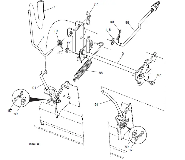
- 2 532 42 20-27 Shaft Asm., Cross Lift
- 3 532 19 52-31 Lever Asm., Lift RH
- 7 580 96 23-01 Grip, Lever
- 10 532 19 63-14 Spring Torsion
- 87 532 19 42-09 Pin Cotter 7/16 Bow Tie Lock
- 88 532 41 07-10 Spring Lift Assist
- 89 819 19 19-12 Washer Clear Zinc
- 90 532 19 42-08 Pin Cotter 5/16 Bow Tie Lock
- 91 532 19 79-84 Link Lift Susp Mower Rear
- 97 817 00 06-12 Screw 3/8-16 x .75 Smgml Tap/R.Z
- 98 532 42 05-25 Link Lift Susp. Front Mower
- 116 819 15 15-16 Washer 15/32 x 15/16 x 16 Ga.
NOTE: All component dimensions given in U.S. inches 1 inch = 25.4 mm
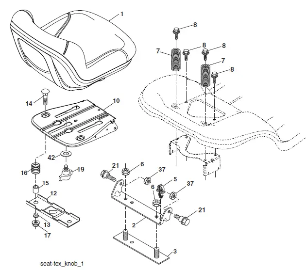
- 1 532 19 75-14 Seat
- 2 532 18 01-66 Bracket Pivot Fender
- 3 532 14 06-75 Strap, Asm Fender
- 5 532 14 50-06 Clip Push-in Hinged
- 6 873 80 06-00 Nut, Lock w/Ins. 3/8-16 unc
- 7 587 61 33-01 Spring, Seat Cprsn
- 8 532 17 18-77 Bolt 5/16-18 unc x 3/4 w/Sems
- 10 532 44 18-05 Pan, Seat
- 12 532 19 93-70 Bracket Mnt.
- 13 532 12 12-48 Bushing Snap
- 14 872 05 04-12 Bolt 1/4-20 x 1-1/2
- 15 532 13 43-00 Spacer Split
- 16 532 12 37-40 Spring CPRSN Plate
- 17 532 12 39-76 Nut Lock 1/4
- 19 532 19 93-72 Knob Seat
- 21 587 90 78-01 Bolt, Shoulder 5/16-18 x 5/8
- 37 873 80 05-00 Nut, Lock 5/16-18 unc
- 42 532 19 93-71 Cup Washer
NOTE: All component dimensions given in U.S. inches 1 inch = 25.4 mm
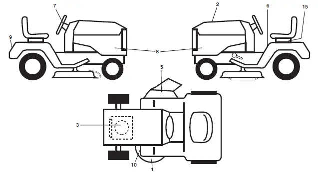
| KEY NO. | PART NO. |
DESCRIPTION | 1 | KEY NO. | PART NO. |
DESCRIPTION |
| 1 | 587 71 20-01 | Decal, Deck Warranty | 15 | 532 14 50-05 | Decal, Caution, Battery | |
| 2 | 585 71 38-01 | Decal, Replacement | – – | 581 72 48-01 | Decal, Bypass | |
| 3 | 585 55 61-01 | Decal, Engine HP | – – | 532 40 95-07 | Pad Foot Pedal RH | |
| 5 | 584 90 46-01 | Decal, Deflect. Warning | – – | 532 40 95-05 | Pad Footrest LH | |
| 6 | 581 57 89-01 | Decal, Fender Warning | – – | 115 78 30-49 | Manual, Operator’s (English/Spanish) | |
| 7 | 587 61 91-01 | Decal, Ins Str Wh | – – | 115 78 31-49 | Manual, Parts (English/Spanish) | |
| 8 | 501 50 36-01 | Decal, Side Panel | – – | 115 63 96-46 | Manual, Quick Start Guide | |
| 9 | 587 61 89-01 | Decal, Fender | (English/Spanish) | |||
| 10 | 581 58 00-01 | Decal, V-Belt Sch. |
WHEELS & TIRES
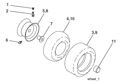
| KEY | PART | |
| NO. | NO. | DESCRIPTION |
| 1 | 532 05 91-92 | Cap, Tire Valve |
| 2 | 532 06 51-39 | Stem, Valve |
| 3 | 532 10 62-22 | Tire, Front 15 x 6-6 |
| 4 | 532 05 99-04 | Tube, Front (Service item only) |
| 5 | 532 12 51-21 | Rim Assembly, 6″ Front |
| 6 | 532 12 49-57 | Fitting, Grease (Front wheel only) |
| 7 | 532 12 49-59 | Bearing, Flange (Front wheel only) |
| 8 | 532 12 51-22 | Rim Assembly, 8″ Rear |
| 9 | 532 13 84-68 | Tire, Rear 20 x 8-8 |
| 10 | 532 12 49-26 | Tube, Rear (Service item only) |
| 11 | 532 19 32-68 | Cap, Hub Axle |
| – – | 532 14 43-34 | Sealant, Tire (10 oz. Tube) |
NOTE: All component dimensions given in U.S. inches 1 inch = 25.4 mm
PARTS AND SERVICE
This product has been expertly en gi needed and carefully many fac turned to rigid quality standards. As with all mechanical products, some adjustments or part replacements may be necessary during the life of your unit.
For Parts and services, contact our authorized distributor: call 1-800-849-1297
- For replacement parts, have available the following information:
- Model Number/Manufacturer’s I.D. Number
- Description of part.
For Technical Assistance: call 1-800-829-5886
For a Parts Manual, go to our website: www.poulanpro.com
NOTE: HOP provides parts and services through its authorized distributors and dealers; therefore, all requests for parts and services should be directed to your local dealer(s). The phi loso phy of HOP is to con tinu ally improve all of its products. If the operating characteristics or the appearance of your product differs from those described in this Manual, please contact your local dealer for updated information and assistance.


