![]()
![]()
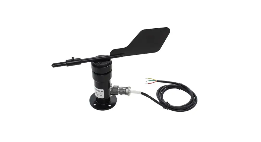
XM5387
User Manual
File Version: V22.2.25 
XM5387 using the standard , easy access to PLC, DCS, and other instruments or systems for monitoring conductivity state quantities.The internal use of high-precision sensing core and related devices to ensure high reliability and excellent long-term stability can be customized
RS232,RS485,CAN,4-20mA,DC0~5V\10V,ZIGBEE,Lora,WIFI,GPRS and other output methods.
Technical Parameters
| Technical parameter | Parameter value |
| Brand | XUNCHIP |
| Wind direction range | 0~360° |
| Wind direction resolution | 22.5° |
| Interface | RS485/4-20mA/DC0-5V |
| Power | DC12~24V 1A |
| Running temperature | -40~80°C |
| Working humidity | 5%RH~90%RH |
Product Selection
Product DesignRS485,4-20mA, DC0-5VMultiple output methods, the products are divided into the following models depending on the output method.
| Product model | Output method |
| XM5387B | RS485 |
| XM5387M | 4-20mA |
| XM5387V5 | DC0-5V |
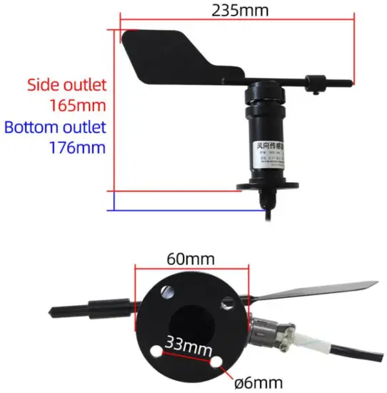
Product Size
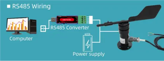
 How to wiring?
 How to wiring?
| RS485 Wiring | Pulse wiring | ||
 | RD PWR+ | | RD PWR+ |
 | GN PWR- |  | BK PWR- |
 | YE RS485 A+ |  | BU Pulse output |
| BU RS485 B- | ||
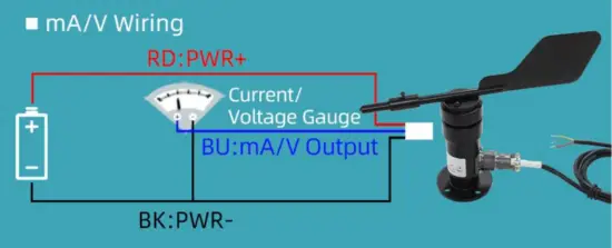
mA Wiring | V Wiring | ||
| RD PWR+ | | RD PWR+ |
| RD PWR+ | | RD PWR+ |
| YE mA Output | | YE V Output |
*Note: When wiring, connect the positive and negative poles of the power supply first and then connect the signal line
Application solution
16 AZIMUTH MAP OF WIND DIRECTOR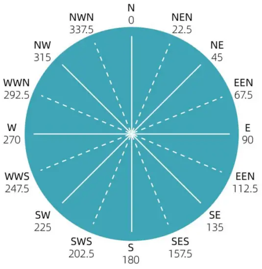
How to use it?

Communication Protocol
The product uses RS485 MODBUS-RTU standard protocol format, all operation or reply commands are hexadecimal data. The default device address is 1 when the device is shipped, the default baud rate is 9600, 8, n, 1
Read Data (Function id 0x03)
Inquiry frame (hexadecimal), sending example: Query 1# device 1 data, the host computer sends the command:01 03 00 00 00 01 84 0A.
| Device ID | Function id | Start Address | Data Length | CRC16 |
| 1 | 3 | 00 00 | 00 01 | 84 0A |
For the correct query frame, the device will respond with data:01 03 02 00 79 79 A6, the response the format is parsed as follows:
| Device ID | Function id | Data Length | Data 1 | Check Code |
| 1 | 3 | 2 | 00 79 | 79 A6 |
Data Description: The data in the command is hexadecimal. Take data 1 as an example. 00 79 is converted to a decimal value of 121. If the data magnification is 100, the actual value is 121/100=1.21. Others and so on.
Data Address Table
| Address | Start Address | Description | Data type | Value range |
| 40001 | 00 00 | conductivity | Read Only | 0~65535 |
| 40101 | 00 64 | model code | read/write | 0~65535 |
| 40102 | 00 65 | total points | read/write | 1~20 |
| 40103 | 00 66 | Device ID | read/write | 1~249 |
| 40104 | 00 67 | baud rate | read/write | 0~6 |
| 40105 | 00 68 | mode | read/write | 1~4 |
| 40106 | 00 69 | protocol | read/write | 1~10 |
Read and modify the device address
- Read or query device address
If you don’t know the current device address and there is only one device on the bus, you can use the command FA 03 00 64 00 02 90 5F Query device address.
| Device ID | Function id | Start Address | Data Length | CRC16 |
| FA | 3 | 00 64 | 00 02 | 90 5F |
FA is 250 for the general address. When you don’t know the address, you can use 250 to get the real device address, 00 64 is the device model register.
For the correct query command, the device will respond, for example, the response data is 01 03 02 07 12 3A 79, the format of which is shown in the following table:
| Device ID | Function id | Start Address | Model Code | CRC16 |
| 1 | 3 | 2 | 55 3C 00 01 | 3A 79 |
The response should be in the data, the first byte 01 indicates that the real address of the current device is, 55 3C converted to decimal 20182 indicates that the current device’s main model is 21820, and the last two bytes 00 01 Indicate that the device has a status quantity.
(2)Change device address
For example, if the current device address is 1, we want to change it to 02, the command is:01 06 00 66 00 02 E8 14.
| Device ID | Function id | Start Address | Destination | CRC16 |
| 1 | 6 | 00 66 | 00 02 | E8 14 |
After the change is successful, the device will return information: 02 06 00 66 00 02 E8 27, its format is parsed as shown in the following table:
| Device ID | Function id | Start Address | Destination | CRC16 |
| 1 | 6 | 00 66 | 00 02 | E8 27 |
The response should be in the data, after the modification is successful, the first byte is the new device address. After the general device address is changed, it will take effect immediately. At this time, the user needs to change the query command of the software at the same time.
Read and Modify Baud Rate
(1) Read baud rate
The device’s default factory baud rate is 9600. If you need to change it, you can change it according to the following table and the corresponding communication protocol. For example, read the current device’s baud rate ID, the command is:01 03 00 67 00 01 35 D5, and its format is parsed as follows.
| Device ID | Function id | Start Address | Data Length | CRC16 |
| 1 | 3 | 00 67 | 00 01 | 35 D5 |
Read the baud rate encoding of the current device. Baud rate encoding: 1 is 2400; 2 is 4800; 3 is 9600; 4 is 19200; 5 is 38400; 6 is 115200.
For the correct query command, the device will respond, for example, the response data is 01 03 02 00 03 F8 45, the format of which is as shown in the following table:
| Device ID | Function id | Data Length | Rate ID | CRC16 |
| 1 | 3 | 2 | 00 03 | F8 45 |
coded according to baud rate, 03 is 9600, ie the current device has a baud rate of 9600.
(2)Change the baud rate
For example, changing the baud rate from 9600 to 38400, ie changing the code from 3 to 5, the command is 01 06 00 67 00 05 F8 1601 03 00 66 00 01 64 15.
| Device ID | Function id | Start Address | Target Baud Rate | CRC16 |
| 1 | 3 | 00 66 | 00 01 | 64 15 |
Change the baud rate from 9600 to 38400, changing the code from 3 to 5. The new baud rate will take effect immediately, at which point the device will lose its response and the baud rate of the device should be queried accordingly. Modified.
Read Correction Value
(1) Read Correction Value
When there is an error between the data and the reference standard, we can reduce the display error by adjusting the correction value. The correction difference can be modified to be plus or minus 1000, that is, the value range is 0-1000 or 64535 -65535. For example, when the display value is too small, we can correct it by adding 100. The command is: 01 03 00 6B 00 01 F5 D6 . In the command 100 is hex 0x64 If you need to reduce, you can set a negative value, such as -100, corresponding to the hexadecimal value of FF 9C, which is calculated as 100-65535=65435, and then converted to hexadecimal to 0x FF 9C. The correction value starts from 00 6B. We take the first parameter as an example. The correction value is read and modified in the same way for multiple parameters.
| Device ID | Function id | Start Address | Data Length | CRC16 |
| 1 | 3 | 00 6B | 00 01 | F5 D6 |
For the correct query command, the device will respond, for example, the response data is : 01 03 02 00 64 B9 AF, the format of which is as shown in the following table:
| Device ID | Function id | Data Length | Data value | CRC16 |
| 1 | 3 | 2 | 00 64 | B9 AF |
In the response data, the first byte 01 indicates the real address of the current device, and 00 6B is the first state quantity correction value register. If the device has multiple parameters, other parameters operate in this way. The same, the general temperature, and humidity have this parameter, the light generally does not have this item.
(2)Change correction value
For example, if the current state quantity is too small, we want to add 1 to its true value, and the current value plus 100 correction operation command is:01 06 00 6B 00 64 F9 FD.
| Device ID | Function id | Start Address | Destination | CRC16 |
| 1 | 6 | 00 6B | 00 64 | F9 FD |
After the operation is successful, the device will return information: 01 06 00 6B 00 64 F9 FD, the parameters take effect immediately after a successful change.
For example, the range is 0~360°, and the analog output is 4~20mA current signal, conductivity, and current The calculation relationship is as shown in the formula: C = (A2-A1) * (X-B1) / (B2-B1) + A1, where A2 is conductivity range upper limit, A1 is the lower limit of the range, B2 is current output range upper limit, B1 is the lower limit, X is the currently read conductivity value, and C is the calculated current value. The list of commonly used values is as follows:
| current(mA) | conductivityValue (°) | Calculation Process |
| 4 | 0 | (360-0)*(4-4)÷ (20-4)+0 |
| 5 | 22.5 | (360-0)*(5-4)÷ (20-4)+0 |
| 6 | 45 | (360-0)*(6-4)÷ (20-4)+0 |
| 7 | 67.5 | (360-0)*(7-4)÷ (20-4)+0 |
| 8 | 90 | (360-0)*(8-4)÷ (20-4)+0 |
| 9 | 112.5 | (360-0)*(9-4)÷ (20-4)+0 |
| 10 | 135 | (360-0)*(10-4)÷ (20-4)+0 |
| 11 | 157.5 | (360-0)*(11-4)÷ (20-4)+0 |
| 12 | 180 | (360-0)*(12-4)÷ (20-4)+0 |
| 13 | 202.5 | (360-0)*(13-4)÷ (20-4)+0 |
| 14 | 225 | (360-0)*(14-4)÷ (20-4)+0 |
| 15 | 247.5 | (360-0)*(15-4)÷ (20-4)+0 |
| 16 | 270 | (360-0)*(16-4)÷ (20-4)+0 |
| 17 | 292.5 | (360-0)*(17-4)÷ (20-4)+0 |
| 18 | 315 | (360-0)*(18-4)÷ (20-4)+0 |
| 19 | 337.5 | (360-0)*(19-4)÷ (20-4)+0 |
| 20 | 360 | (360-0)*(20-4)÷ (20-4)+0 |
As shown in the above formula, when measuring 8mA, the current is 94°。
For example, the range is 0~360°, the analog output is 0~5V DC0-5Vvoltage signal, conductivity, and DC0-5Vvoltage The calculation relationship is as shown in the formula: C = (A2-A1) * (X-B1) / (B2-B1) + A1, where A2 is conductivity range upper limit, A1 is the lower limit of the range, B2 is DC0 -5Vvoltage output range upper limit, B1 is the lower limit, X is the currently read conductivity
| DC0-5Vvoltage(V) | conductivity value (°) | Calculation Process |
| 0 | 0 | (360-0)*(0-0)÷ (5-0)+0 |
| 1 | 72 | (360-0)*(1-0)÷ (5-0)+0 |
| 2 | 144 | (360-0)*(2-0)÷ (5-0)+0 |
| 3 | 216 | (360-0)*(3-0)÷ (5-0)+0 |
| 4 | 288 | (360-0)*(4-0)÷ (5-0)+0 |
| 5 | 360 | (360-0)*(5-0)÷ (5-0)+0 |
y value and C is the calculated DC0-5Vvoltage value. The list of commonly used values is as follows:
As shown in the above formula, when measuring 2.5V, the current DC0-5Vvoltage is 180°。
Disclaimer
This document provides all information about the product, does not grant any license to intellectual property, does not express or imply, and prohibits any other means of granting any intellectual property rights, such as the statement of sales terms and conditions of this product, other issues. No liability is assumed. Furthermore, our company makes no warranties, express or implied, regarding the sale and use of this product, including the suitability for the specific use of the product, the marketability, or the infringement liability for any patent, copyright, or other intellectual property rights, etc. Product specifications and product descriptions may be modified at any time without notice.
Contact Us
Brand: XUNCHIP/Xunxin
Address: Room 208, Building 8, No. 215, Nandong Road, Baoshan District, Shanghai, Xinxin Brand
Business Department
Chinese site: http://www.xunchip.com
International site: http://www.xunchip.com
SKYPE: soobuu
E-mail: [email protected]
Tel: 86-021-51083595 / 66862055 / 66862075 / 66861077
Sha nghai XUNCHIP Industrial Co., Ltd XUNCHIP Brand Division


