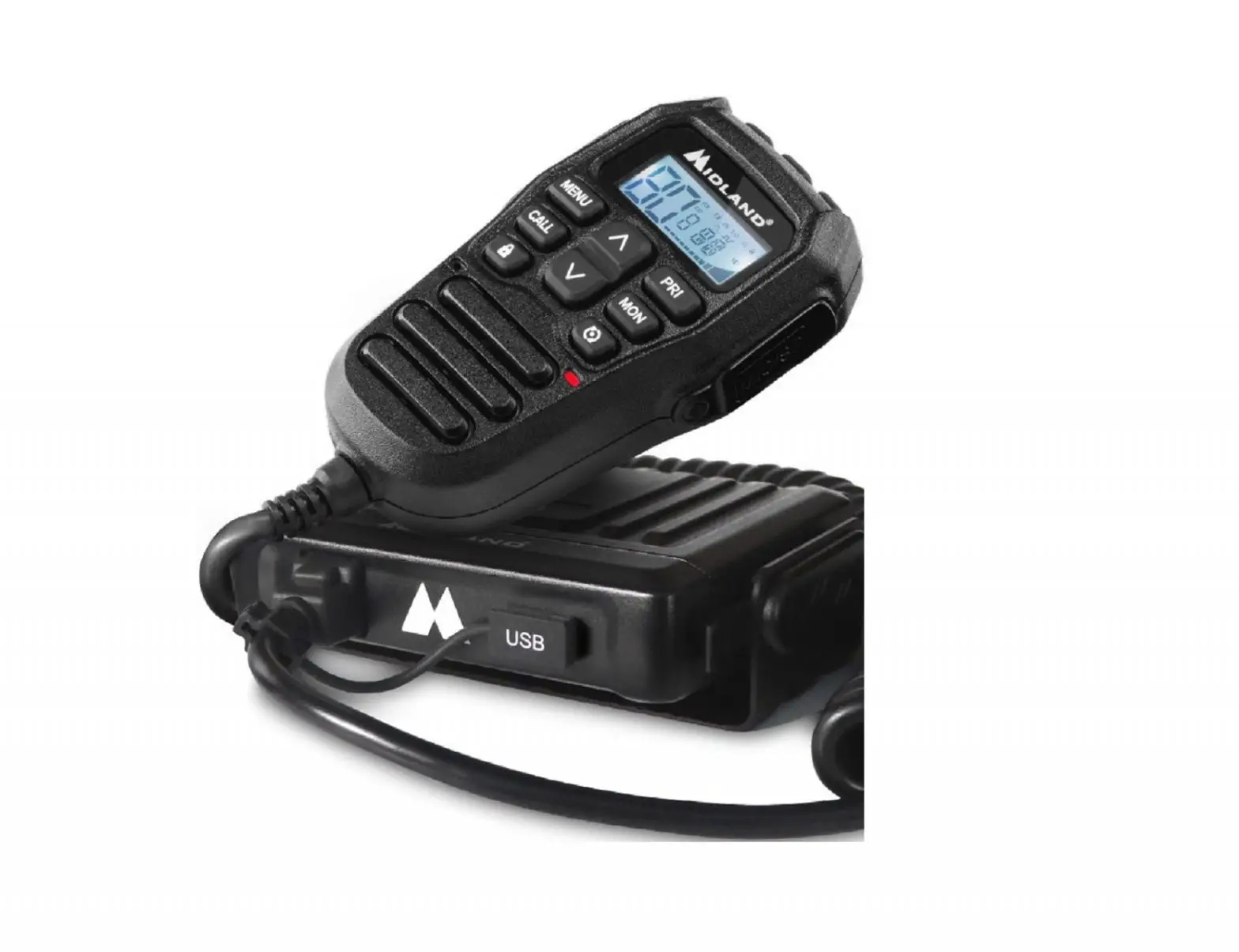
MIDLAND PRO902 HEAVY DUTY UHF CB/LMR with REMOTE SPEAKER MIC User Manual
Specifications:
- Output Power: 5 Watts (CB), 15 Watt (LMR)
- CB Channels: 2 Banks: 80(CB), 19 (LMR – Dealer Programmable)
- CB Frequency Range: 476.425 ~ 477.4125MHz
- LMR Frequency Range: 450 ~ 520MHz
- Channel Width: 12.5kHz (Narrowband + Wideband))
- Power Source (Nominal): 13.8V
- Max Absorption Current in TX: 1.3A (5W), <3.2A (15W)
- Operation Mode: Simplex & Duplex
- Audio Output Power: 4 Watt (Base & Microphone)
- Digital Coded Squelch (DCS): 104
- Interference Eliminator (CTCSS): 50
- Duplex Capability: Yes
- Channel Memory Scan: Yes
- Scan/Priority Scan: Yes
- Backlit LCD Display: Yes, 7 Colour (Selectable)
- External Speaker Jack: Yes
- TX/RX Indicator: Yes
- Scanning Receive Functions: Yes
- Key Lock: Yes
- Key Beep On/Off: Yes
- Auto Squelch: Yes
- Speaker: Dual (Base & Microphone)
- USB Charging Port: Yes
- Typical Range: 18km Line of Sight
- Slide-In Mounting Cradle: Yes
- Dimensions: (excl bracket) 110H x 120W x 25D mm
Included:
- Dual Mounting Brackets
- Microphone Hanger
- Adaptor Cable
Introduction
Thank you for purchasing this MIDLAND in-vehicle HYBRID UHF/CB radio.
Please read this manual carefully to understand its functions and operations.
The PRO902 you purchased is an advanced UHF in-vehicle two way radio. PRO902 combines the very latest in electronic hardware with the most up-to date computer aided design and manufacturing techniques to produce an extremely compact mobile radio with outstanding specifications and performance.
PRO902 has remote controls built into the microphone. The radio is designed for unobtrusive mounting in modern vehicles with limited space. Its innovative features include built-in loud-speakers housed within an extremely compact case and the remote microphone.
Note: The use of the Citizen Band radio service is licensed in Australia by ACMA Radio Communications (Citizen Band Radio Stations) Class license and in New Zealand by the Ministry of Economic Development New Zealand.
Thank you for your support and interest in our products!
Maintenance service and support
The Company provides long-term support for its products. This support includes maintenance, spare parts and warranty within the warranty period.
After the expiry of the warranty
The company provides technical services and spare parts to authorized radio dealers.
The ordering of replacement parts
When ordering replacement parts or equipment information, please specify the complete part code. All parts include part number, components or chassis. If you do not know the part code, please indicate the chassis or group that the part relates to.
Personal safety
For personal safety, please disconnect all power and RF cables before attempting any repair work.
![]() All articles displaying this symbol on the body, packaging or instruction manual must not be thrown away in normal waste bins but should be placed in recycling bins or taken to a specialised waste disposal centre.
All articles displaying this symbol on the body, packaging or instruction manual must not be thrown away in normal waste bins but should be placed in recycling bins or taken to a specialised waste disposal centre.
![]() This symbol assures that a device complies with all applicable ACMA regulatory arrangements for radio communication equipment used in Australian UHF citizen band radio service.
This symbol assures that a device complies with all applicable ACMA regulatory arrangements for radio communication equipment used in Australian UHF citizen band radio service.
What’s Included
Please carefully unpack the transceiver from the carton.
Please check that all accessories are included.
| SPARE PARTS | UNITS | QUANTITY |
| In-vehicle radio | pc | 1 |
| Mounting brackets (U and Quick Release) | pc | 2 |
| Microphone | pc | 1 |
| Microphone bracket | pc | 1 |
| Microphone Extension Cable (2m) | pc | 1 |
| User manual | pc | 1 |
| Power cable | pc | 1 |
| Power Adaptor Cable | pc | 1 |
| Screws | pc | 1 |
Please contact the retailer if any parts are missing.
Emergency Channel
ACMA has pre-allocated channels 5/35. Channel 5 is only for emergency application.
Channel 5 repeater access is available in most areas. Activate duplex on Channel 5.
Telecommand Channels
ACMA has reserved Channel 22 and Channel 23 as telecommand channels. Transmission is prohibited on these channels. PRO901 blocks transmission on these 2 channels. Channels 61, 62 and 63 are for future use and TX is inhibited on these channels.
Commercial UHF-LMR
The PRO902 features hybrid funcionality allowing high power (13-17 Watt) use on UHFLMR commercial frequencies. Please note that according to ACMA regulations this is only permissable for authorised commercial license holders. Activation of this high power LMR function can only be done with licensed Midland software available through authorised dealers and agents.
Features
Microprocessor Controlled Frequency Synthesiser
Allows user programmable control of scanning, channel memories and selected options.
Scanning Function
Quickly finds radio channels.
Individually Programmable DUPLEX Function
Selectable only for individual channels in areas that can access a repeater. This leaves others free for use as simplex channels.
High Contrast Liquid Crystal Display
Fully detailed LCD provides a visual indication of the selected channel and all selected functions. Backlit for night viewing.
Compact Size
Fits into the smallest locations allowing installations in space challenged environments
CTCSS & DCS
A built-in Continuous Tone Coded Squelch and Digital Coded Squelch System option provides quiet channel operation.
Overvoltage Protection
Special overvoltage detection circuitry protects the radio and warns of excessive voltage conditions by flashing the display.
Surface Mount Technology
The very latest surface-mount components, design, assembly techniques and quality control procedures are used to ensure high performance and reliability.
General Operation
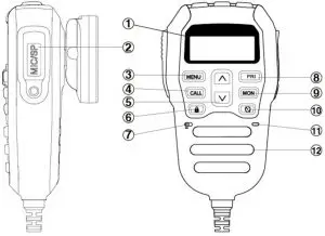
- LCD
- Mic/Programming Socket
- Menu
- Call
- Function Select
- Key Lock
- Mic
- Priority Channel
- Monitor
- Scan
- T/R LED
- Speaker
- Channel Down
- Power
- Channel Up
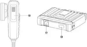
- PTT (Press to talk)
- Mic Connector
- USB Port (Charging)
About Banks
The radio is designed with 2 bands. BANK1 is fixed to low power (LCD does not display Lo for 80 UHF/CB channels). The frequency range is: 476.425 – 477.4125MHz. Channels 1-80 are fixed for Australian frequencies. BANK2 450-520MHz LMR frequency for Channels 81-99. These channels can be programmed using optional programming software available to authorised dealers.
They can also be switched to high and low power (LCD will show Hi/Lo).
BANK1 and BANK2 switching mode: LOCK + MON, the liquid crystal display will show P1 (bank1), P2 (bank2)
Power
- To turn on, briefly press the
 key for three seconds.
 - To turn off, briefly press the key for three seconds.


Key Lock
With radio in standby, press ![]() for three seconds. Then the LCD will display
for three seconds. Then the LCD will display ![]() icon. To unlock press
icon. To unlock press ![]() button for three seconds.
button for three seconds.
When radio is in key lock, only the volume function can be adjusted. The radio mode will display “LC” if any button is pressed.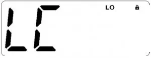
Volume
Press the ˄ or ˅ keys to increase or decrease the volume. The radio will beep with each key press and the display will flash to indicate the volume setting. The volume level can be set from 00 (min) to 09 (max). The display will stop flashing and return to the selected channel display a few seconds after the last volume adjustment.
Selecting Channels
Press the ▲ or ▼ keys to step up or down through the channels.
Transmitting
To transmit, press the PTT button. Hold the microphone about 5-8 cm from your face and speak at a normal voice level. The microphone is quite sensitive so it is not necessary to raise your voice or shout. Release the PTT when you have finished talking.
IMPORTANT: Always listen to ensure the channel is free before transmitting.
CTCSS (Continuous Tone Coded Squelch System) and DCS (Digitally Coded Squelch)
CTCSS (Continuous Tone Coded Squelch System) and DCS (Digitally Coded Squelch) are squelch quieting systems that allow several groups of users to share the same channel without disturbing each other. The system applies a continuous low-level tone to your transmission and uses a matching tone decoder to control your receiver’s Squelch. With CTCSS or DCS enabled, the channel remains quiet to all incoming signalsunless they carry the correct tone. When a transmission with the correct tone is received, the squelch opens and remains open for as long as the signal is present. When the transmission ends the channel becomes quiet again. Transmissions that do not use the correct tone will not to be heard. There are two tone sets installed in your PRO902 comprising 50 CTCSS and 104 DCS user-selectable tones.
The PRO902 allows CTCSS or DCS to be enabled or disabled on individual channels.
Note: The CTCSS/DCS tone you select will be used for all CTCSS/DCS enabled channels in your radio.
Selecting the CTCSS or DCS
Choosing which tone to use will probably be dependent on the other radios you talk to. If you talk to others outside your group who already use CTCSS or DCS tones you will needto select the tone that matches theirs.
The PRO902 includes most of the commonly used tone sets.
If the users you talk to don’t currently use CTCSS or DCS, choose your own tones.
There is no difference in performance between the two tone sets.
The CTCSS and DCS tones are stored in your radio in a sequential table. The first table location is OFF. The next 50 locations are CTCSS tones followed by 104 DCS tones.
OFF -> CTCSS 01 to CTCSS 50 OFF-> DCS01 to DCS 104
To Select CTCSS Tone
- Briefly press MENU key to enter the MENU function.
- Then press ▲ or ▼ in the menu to enter your choice.
Then press the Lock key on the handset to enter the sub-audio selection menu, then select the category by pressing the handset’s function selection key, ~ represents CTCSS (analog sub-audio), DCS (digital sub-audio), OF represents no sub tone.
(The unit provides 50 sets of CTCSS and 104 sets of DCS) - After selecting the sub-audio category you want to set, press the Lock key to confirm your choice.
- Then press the handset function select button to confirm the selection of the desired sub-audio group, and then press
 to confirm your choice
Note: If you select a CTCSS personal code, the previously set code will be canceled. In the channel 5 and channel 35 is not allowed to set sub-audio, this feature is invalid.

Once a DCS or CTCSS code is selected, your radio will now be in “Silent” mode on that channel and will remain muted in that channel unless a signal containing your selected CTCC/DCS tone is received. Channels that do not have CTCSS/DCS enabled will remain open to all signals.
You may activate CTCSS/DCS on as many channels as you wish except channel 5 which is designated for emergency use.
Note: CTCSS/DCS may not work through some repeaters.
To Monitor the Channel
Briefly press the “MON” key. If there are no signals present, you will hear the usual hiss of an empty channel. Press the “MON” key again to restore the Squelch to its previous setting.
Squelch Control
Squelch control is used to eliminate the background noise when there are no signals present. The PRO902 features a preset Squelch system. The Squelch sensitivity has been factory set to provide optimum performance in most environments. The sensitivity can be altered by the user if required to suit varying environmental situations. The Squelch can be opened or closed by pressing the “MON” key. When the Squelch is open, the receiver’s background noise can be heard and ![]() is displayed. When the Squelch is closed, the receiver remains quiet when there are no present signals but an incoming signal will override the squelch and be heard through the speaker.
is displayed. When the Squelch is closed, the receiver remains quiet when there are no present signals but an incoming signal will override the squelch and be heard through the speaker.
To Open the Squelch
Briefly press the “MON” key again. A low beep will be heard. If there no signals present you will hear the receiver’s background noise.
To Adjust the Preset Squelch Sensitivity
- Briefly press the MENU key to enter the menu .
- Then press ▲ or ▼ key to select and stop when the LCD display “Sq”, and briefly press the key to confirm and enter squelch sensitivity setting.
- Then you can press ▲ or ▼ key to choose the squelch sensitivity level you want, and press the key to confirm
The default setting is 05 which generally provides reliable squelch operation for most applications.

Squelch Sensitivity
The sensitivity of the Squelch to incoming signals can be set to suit your operating environment.
For example, excessively noisy environments may cause the squelch to open on local noise.
The PRO902 has nine preset Squlech sensitivity settings.
Backlight
- Briefly press the MENU key to enter the menu.
- Then press ▲ or ▼ key to select and stop when the LCD display “db”, and briefly press the key to confirm and enter backlight setting.
- Then you can press ▲ or ▼ key to choose the desired backlight color, and briefly press the key to confirm.
Select ‘OFF’ or one of the 7 colour options: Green, Red, Yellow, Blue, Cyan, Magenta, White.

Duplex Operation
Press and hold the MENU key on channels 1-8 and channels 41-48 to enable the Duplex operation.Duplex operation allows the radio to transmit on a different frequency to that which it receives allowing operation through repeater stations. Repeaters automatically retransmit your signal over a wider area providing greatly increased range. Duplex operates only on channels 1-8 & 41-48. When duplex is selected on these channels, the radio receives on that channel but actually transmits 30 channels higher. In repeater mode, the radio only operates on repeater channels.
- Channel Selecting : 1 2 3 4 5* 6 7 8
- Receiving Channel : 1 2 3 4 5* 6 7 8
- Transmitting Channel : 31 32 33 34 35* 36 37 38
- Channel Selecting : 41 42 43 44 45* 46 47 48
- Receiving Channel : 41 42 43 44 45* 46 47 48
- Transmitting Channel : 71 72 73 74 75* 76 77 78
* Channel only for Emergency.

PRI Channel
The Priority Channel feature allows you to immediately recall any one of your channels with instant access to your working channel or your local repeater with one button.
PRI Channel Setting
- Select the channel you requested
- Press and hold the PRI function key, then enter the priority channel setting, and then select the priority channel through the channel selection key. When selecting the channel you requested, press the PRI function key for a second time to complete the priority channel setting.


Call Back the PRI Channel
Press the PRI function key, the intercom will switch to the set priority channel immediately after the PC logo is displayed. PRI short press the function key again to exit the priority channel mode.
When you press the PTT button, the LCD will display the PC logo instead of the priority channel number.

Note: If the PRI function key is pressed while the intercom is in the scanning status, it will exit the scan mode.
Scanning
PRO902 has a SCAN function that allows a selection of user programmable channels to be scanned for signals. Channels are scanned at 4 channels per second. When a signal is found, scanning will pause on that channel to allow the signal to be heard. Scanning will resume when the channel is clear again.
To Start and Stop Scanning
To begin scanning, briefly press the ![]() key. A beep will be heard, and the
key. A beep will be heard, and the ![]() icon will be displayed on the LCD and the radio will begin scanning.
icon will be displayed on the LCD and the radio will begin scanning.
If a busy channel is found, scanning will pause on that channel to allow the signal to be heard and will remain there for as long as the channel remains busy. Once the channel has been clear for 5 seconds, scanning will resume automatically.
If your radio is paused on a busy channel and you wish to remain there, briefly press the ![]() key. The radio will exit Scan mode and remain on the busy channel.
key. The radio will exit Scan mode and remain on the busy channel.
If the radio pauses on a busy channel and you don’t wish to listen to the conversation, briefly press either of the ▲ or ▼ keys. The radio will skip over that channel and resume scanning from the next channel in the sequence.
Briefly press the ![]() key again to stop scanning and it will return to the previous channel.
key again to stop scanning and it will return to the previous channel.
To Activate Repeater Channels
- Press and hold the MENU button for 3 seconds to activate the relative repeater channel.
This works only if you are on the list of channels able to have repeater channels.
Example: On CH5 display shows “05” Press and hold the MENU button for 3 seconds. The radio changes from 05 to “05R”. The display then shows a small “R” behind the channel number.
If you are on CH10 keep pressing the MENU button (nothing happens) you have the double beep sound (to identify error procedure) and the radio still on CH10. - If you press UP/DW button (to change the channel) the channel is on the changed repeater only: 01R – 02R – 03R……08R – 41R – 42R…..48R – 01R
- To return to “standard channels” keep pressing the MENU button 3 seconds more.
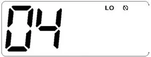
Reset Function
When the radio is off, press PTT+PRI+POWER at the same time.
During resetting, the software version number (current version number is 4A) will be displayed. After reset, the radio will be in the default setting.
Default Setting Table
| SQL | 5 |
| Roger Beep | OFF |
| CTCSS/CDCSS | OFF |
| Volume | 6 |
| Beep | ON |
| Backlight | 07 |
| Call Tone | 1 |

Call Tone
Press Call button and the radio will send a call alarm signal. The caller can hear the tone to confirm the display. There is a TX icon displayed.
Note: When you send out an alarm signal, the signal will only last for three seconds in a minute.
After one minute the alarm will continue.
Call Tone Setting
- Briefly press the menu key to enter the menu.
- Press ▲ or ▼ key to select and stop when the LCD display “CA”. Press the key to confirm and enter calltone setting.
- Press ▲ or ▼ key to choose the desired setting, and briefly press the key to confirm. There are 5 kinds of sounds from 01 to 05.


High/Low Power Selecting (In Power OFF Mode)
Change Hi/Lo power mode by pressing PTT+CALL+MENU+POWER at the same time (For bank2, bank1 is locked in low power mode).
- High Power, LCD displays Hi.
- Low Power, LCD displays Lo.
Roger Beep
- Briefly press the menu key to enter the menu.
- Then press ▲ or ▼ key to select and stop when the LCD displays “rb”, and press the key to confirm and enter Roger Beep setting.
- Press ▲ or ▼ key to choose ON/OFF. Briefly press the key to confirm.


Keytone Setting
- Briefly press the MENU key to enter the menu.
- Then press ▲ or ▼ key to select and stop when the LCD displays “bp”. Press the key to confirm and enter keytone setting.
- Press ▲ or ▼ key to choose ON/OFF. Briefly press the key to confirm.


Wide/Narrow Band
Wide/Narrow Band select only through PC programming.
USB Charger
Charging power for cellphones and other devices.
Speaker Selection
When the radio is ON, press ![]() to switch “HO AF” or “HF AO”.
to switch “HO AF” or “HF AO”.
“HO AF” activates base unit speaker. Microphone speaker will be OFF.
“HF AO” switches base unit speaker off. Microphone speaker will be ON.
Dual Speaker Function (Bank 2)
“HO AO” means base and mic speaker ON. To activate this: ![]() button.
button.
Note: In BANK 1, 477MHz this operation cannot be activated.
Appendix
Two Way Radio Frequency List
| CH | Simplex Mode Frequency (MHz) | Duplex Mode Frequency (MHz) | CH | Simplex Mode Frequency (MHz) | CH | Simplex Mode Frequency (MHz) | Duplex Mode Frequency (MHz) | CH | Simplex Mode Frequency (MHz) |
| 01 | 476.4250 | 477.1750 (CH31) Repeater TX | 21 | 476.9250 | 41 | 476.4375 Repeater RX | 477.1875 (CH71) Repeater Transmit | 61 | 476.9375 (RX Only) Future Use |
| 02 | 476.4500 | 477.2000 (CH32) Repeater TX | 22 | 476.9500 Data Only | 42 | 476.4625 Repeater RX | 477.2125 (CH72) Repeater Transmit | 62 | 476.9625 (RX Only) Future Use |
| 03 | 476.4750 | 477.2250 (CH33) Repeater TX | 23 | 476.9750 Data Only | 43 | 476.4875 Repeater RX | 477.2375 (CH73) Repeater Transmit | 63 | 476.9875 (RX Only) Future Use |
| 04 | 476.5000 | 477.2500 (CH34) Repeater TX | 24 | 477.0000 | 44 | 476.5125 Repeater RX | 477.2625 (CH74) Repeater Transmit | 64 | 477.0125 |
| 05 | 476.5250 Emergency Only | 477.2750 (CH35) Repeater TX | 25 | 477.0250 | 45 | 476.5375 Repeater RX | 477.2875 (CH75) Repeater Transmit | 65 | 477.0375 |
| 06 | 476.5500 | 477.3000 (CH36) Repeater TX | 26 | 477.0500 | 46 | 476.5625 Repeater RX | 477.3125 (CH76) Repeater Transmit | 66 | 477.0625 |
| 07 | 476.5750 | 477.3250 (CH37) Repeater TX | 27 | 477.0750 | 47 | 476.5875 Repeater RX | 477.3375 (CH77) Repeater Transmit | 67 | 477.0875 |
| 08 | 476.6000 | 477.3500 (CH38) Repeater TX | 28 | 477.1000 | 48 | 476.6125 Repeater RX | 477.3625 (CH78) Repeater Transmit | 68 | 477.1125 |
| 09 | 476.6250 | 29 | 477.1250 | 49 | 476.6375 | 69 | 477.1375 | ||
| 10 | 476.6500 | 30 | 477.1500 UHF CB Broadcast | 50 | 476.6625 | 70 | 477.1625 | ||
| 11 | 476.6750 Call Channel | 31 | 477.1750 Repeater Input | 51 | 476.6875 | 71 | 477.1875 Repeater Input | ||
| 12 | 476.7000 | 32 | 477.2000 Repeater Input | 52 | 476.7125 | 72 | 477.2125 Repeater Input | ||
| 13 | 476.7250 | 33 | 477.2250 Repeater Input | 53 | 476.7375 | 73 | 477.2375 Repeater Input | ||
| 14 | 476.7500 | 34 | 477.2500 Repeater Input | 54 | 476.7625 | 74 | 477.2625 Repeater Input | ||
| 15 | 476.7750 | 35 | 477.2750 Emergency Only | 55 | 476.7875 | 75 | 477.2875 Repeater Input | ||
| 16 | 476.8000 | 36 | 477.3000 Repeater Input | 56 | 476.8125 | 76 | 477.3125 Repeater Input | ||
| 17 | 476.8250 | 37 | 477.3250 Repeater Input | 57 | 476.8375 | 77 | 477.3375 Repeater Input | ||
| 18 | 476.8500 | 38 | 477.3500 Repeater Input | 58 | 476.8625 | 78 | 477.3625 Repeater Input | ||
| 19 | 476.8750 | 39 | 477.3750 | 59 | 476.8875 | 79 | 477.3875 | ||
| 20 | 476.9000 | 40 | 477.4000 Highway Channel | 60 | 476.9125 | 80 | 477.4125 |
CTCSS: 50 Groups of CTCSS Frequencies
| 01 | 67.0 | 11 | 94.8 | 21 | 131.8 | 31 | 171.3 | 41 | 203.5 |
| 02 | 69.3 | 12 | 97.4 | 22 | 136.5 | 32 | 173.8 | 42 | 206.5 |
| 03 | 71.9 | 13 | 100.0 | 23 | 141.3 | 33 | 177.3 | 43 | 210.7 |
| 04 | 74.4 | 14 | 103.5 | 24 | 146.2 | 34 | 179.9 | 44 | 218.1 |
| 05 | 77.0 | 15 | 107.2 | 25 | 151.4 | 35 | 183.5 | 45 | 225.7 |
| 06 | 79.7 | 16 | 110.9 | 26 | 156.7 | 36 | 186.2 | 46 | 229.1 |
| 07 | 82.5 | 17 | 114.8 | 27 | 159.8 | 37 | 189.9 | 47 | 233.6 |
| 08 | 85.4 | 18 | 118.8 | 28 | 162.2 | 38 | 192.8 | 48 | 241.8 |
| 09 | 88.5 | 19 | 123.0 | 29 | 165.5 | 39 | 196.6 | 49 | 250.3 |
| 10 | 91.5 | 20 | 127.3 | 30 | 167.9 | 40 | 199.5 | 50 | 254.1 |
104 Groups of DCS Frequencies
| 01 | 023 | 19 | 116 | 37 | 225 | 55 | 325 | 73 | 452 | 91 | 627 |
| 02 | 025 | 20 | 122 | 38 | 226 | 56 | 331 | 74 | 454 | 92 | 631 |
| 03 | 026 | 21 | 125 | 39 | 243 | 57 | 332 | 75 | 455 | 93 | 632 |
| 04 | 031 | 22 | 131 | 40 | 244 | 58 | 343 | 76 | 462 | 94 | 654 |
| 05 | 032 | 23 | 132 | 41 | 245 | 59 | 346 | 77 | 464 | 95 | 662 |
| 06 | 036 | 24 | 134 | 42 | 246 | 60 | 351 | 78 | 465 | 96 | 664 |
| 07 | 043 | 25 | 143 | 43 | 251 | 61 | 356 | 79 | 466 | 97 | 703 |
| 08 | 047 | 26 | 145 | 44 | 252 | 62 | 364 | 80 | 503 | 98 | 712 |
| 09 | 051 | 27 | 152 | 45 | 255 | 63 | 365 | 81 | 506 | 99 | 723 |
| 10 | 053 | 28 | 155 | 46 | 261 | 64 | 371 | 82 | 516 | A0 | 731 |
| 11 | 054 | 29 | 156 | 47 | 263 | 65 | 411 | 83 | 523 | A1 | 732 |
| 12 | 065 | 30 | 162 | 48 | 265 | 66 | 412 | 84 | 526 | A2 | 734 |
| 13 | 071 | 31 | 165 | 49 | 266 | 67 | 413 | 85 | 532 | A3 | 743 |
| 14 | 072 | 32 | 172 | 50 | 271 | 68 | 423 | 86 | 546 | A4 | 754 |
| 15 | 073 | 33 | 174 | 51 | 274 | 69 | 431 | 87 | 565 | ||
| 16 | 074 | 34 | 205 | 52 | 306 | 70 | 432 | 88 | 606 | ||
| 17 | 114 | 35 | 212 | 53 | 311 | 71 | 445 | 89 | 612 | ||
| 18 | 115 | 36 | 223 | 54 | 315 | 72 | 446 | 90 | 624 |
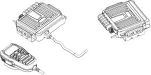
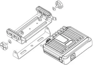
Dismantling and Assembly Drawings
- The whole chart

- Bracket Assembly Diagram

WARRANTY
Congratulations on your purchase of a quality ![]() Mobile Communication Product! You’re joining thousands of satisfied customers who enjoy & experience the benefits of the products we distribute. In the unlikely event that some technical difficulty arises with your purchase, be assured that we are most anxious to see that the problem is quickly rectified to your satisfaction. Please familiarise yourself with the following simple conditions of our warranty. This warranty covers faults through component failure or failure of the product to operate in accordance with published specifications. Product failure as a result of unreasonable environmental conditions, accident, misuse, improper installation, unauthorised repair, vehicle electrical or wiring faults or neglect etc, will not be covered by this warranty. Removal and installation costs, if any, would be paid by the owner as well as any freight or postage costs of transporting the product to AudioXtra. AudioXtra shall not be liable or responsible for any loss of use of this product or any form of consequential loss.
Mobile Communication Product! You’re joining thousands of satisfied customers who enjoy & experience the benefits of the products we distribute. In the unlikely event that some technical difficulty arises with your purchase, be assured that we are most anxious to see that the problem is quickly rectified to your satisfaction. Please familiarise yourself with the following simple conditions of our warranty. This warranty covers faults through component failure or failure of the product to operate in accordance with published specifications. Product failure as a result of unreasonable environmental conditions, accident, misuse, improper installation, unauthorised repair, vehicle electrical or wiring faults or neglect etc, will not be covered by this warranty. Removal and installation costs, if any, would be paid by the owner as well as any freight or postage costs of transporting the product to AudioXtra. AudioXtra shall not be liable or responsible for any loss of use of this product or any form of consequential loss.
CONSUMER WARRANTY
This product is warranted by AudioXtra Pty Ltd to be free from defects in materials and workmanship under NORMAL USE for a period of FIVE YEARS from the date of purchase. The battery and accessories are warranted for TWELVE MONTHS. To claim bonus 2 year warranty visit www.midlandaustralia.com.au to register your product.
WITHIN 30 DAYS OF PURCHASE DATE:
Please return the unit for replacement to our National Service Centre or the Retailer from where you made the purchase. All accessories must be included. Proof of purchase date must accompany the products.
AFTER 30 DAYS OF PURCHASE DATE:
Warranty repair and service is carried out by our National Service Centre. Repair and service will be carried out at no cost to the owner if proof of ownership and the date of purchase can be verified to the satisfaction of the authorised centre concerned with this repair. This proof should take the form of either:
- The warranty card accompanying this product, stamped and dated by the dealer.
- A Tax Invoice or Receipt showing full details of original vendor, purchaser, model number and serial number.
COMMERCIAL WARRANTY
A product used in or associated with a commercial application will carry a limited SIX MONTH warranty. An abnormal commercial application is one where usage, dust, vibration, heat/cold and other environmental conditions exist at an extreme level.
Our goods come with guarantees that cannot be excluded under the Australian Consumer Law. You are entitled to a replacement or refund for a major failure and for compensation for any other reasonably foreseeable loss or damage.
You are also entitled to have the goods repaired or replaced if the goods fail to be of acceptable quality and the failure does not amount to a major failure.
Please complete details below in the event of warranty service being required.
Purchaser’s Name: __________________________________________
Purchaser’s Address: _________________________________________
Model Number: ___PRO902________ Serial Number: __________
Dealer Name: __________________ Date of Purchase: / /
Dealer Address:____________________________________________
Invoice/Sales Docket no: __________________________________
General Hints: To expedite service and prompt return of the equipment, please:
- Clearly describe the fault in detail
- Safely and securely pack the unit for transport
- Include your return address
- Provide proof of purchase date as outlined above.
National Service Centre:
10 STODDART ROAD, PROSPECT, SYDNEY NSW 2148 Australia
Telephone: (02) 8841 9000
Fax: (02) 9636 1204
email: [email protected]


