
ABUS
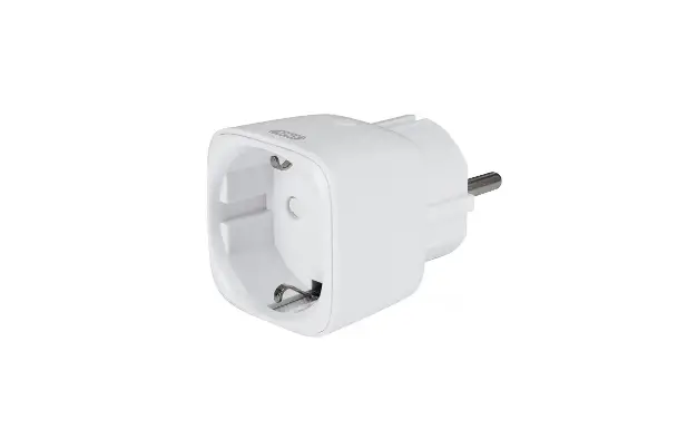
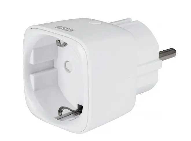
ABUS Z-Wave Wireless-Socket
SKU: SHHA10000


Quickstart
This is a
secure
On/Off Power Switch
for
CEPT (Europe).
To run this device please connect it to your mains power supply.
To add this device to your network execute the following action:
A.) Plug the Wireless-Socket into an outlet. The Status-LED is flashing.B.) Click the + (Add) button in your Z-Wave App and follow the further instructionsC.) Press the Network-Button on the Socket once. The App will show if the Add device process was successful. The Status LED does not flash anymore but indicates if device is switched on or off. Repeat the inclusion process from step B if it was not successful.
Please refer to the
Manufacturers Manual for more information.
Important safety information
Please read this manual carefully. Failure to follow the recommendations in this manual may be dangerous or may violate the law.
The manufacturer, importer, distributor and seller shall not be liable for any loss or damage resulting from failure to comply with the instructions in this manual or any other material.
Use this equipment only for its intended purpose. Follow the disposal instructions.
Do not dispose of electronic equipment or batteries in a fire or near open heat sources.
What is Z-Wave?
Z-Wave is the international wireless protocol for communication in the Smart Home. This
device is suited for use in the region mentioned in the Quickstart section.

Z-Wave ensures a reliable communication by reconfirming every message (two-way
communication) and every mains powered node can act as a repeater for other nodes
(meshed network) in case the receiver is not in direct wireless range of the
transmitter.
This device and every other certified Z-Wave device can be used together with any other
certified Z-Wave device regardless of brand and origin as long as both are suited for the
same frequency range.
If a device supports secure communication it will communicate with other devices
secure as long as this device provides the same or a higher level of security.
Otherwise it will automatically turn into a lower level of security to maintain
backward compatibility.
For more information about Z-Wave technology, devices, white papers etc. please refer
to www.z-wave.info.
Product Description
the ABUS Z-Wave Wireless Socket is a compact plug adapter for switching connected devices and power metering. It includes a repeater function for extending the range of the Z-Wave radio signal. The Socket can be triggered remotely via the contected Gateway or by a button on the device.
Prepare for Installation / Reset
Please read the user manual before installing the product.
In order to include (add) a Z-Wave device to a network it must be in factory default
state. Please make sure to reset the device into factory default. You can do this by
performing an Exclusion operation as described below in the manual. Every Z-Wave
controller is able to perform this operation however it is recommended to use the primary
controller of the previous network to make sure the very device is excluded properly
from this network.
Reset to factory default
This device also allows to be reset without any involvement of a Z-Wave controller. This
procedure should only be used when the primary controller is inoperable.
1. Keep pressing the Button on the socket for more than 5 seconds (the flash interval of the Status LED is now accelerated)2. The wireless socket is now restored to factory settingsNote: 1, This procedure should only be used if the primary gateway is not capable of acting. 2, If the multi-sensor is set to the factory setting, the status is set to “not included”, the association settings and possible configurations are reset to default.
Safety Warning for Mains Powered Devices
ATTENTION: only authorized technicians under consideration of the country-specific
installation guidelines/norms may do works with mains power. Prior to the assembly of
the product, the voltage network has to be switched off and ensured against re-switching.
Inclusion/Exclusion
On factory default the device does not belong to any Z-Wave network. The device needs
to be added to an existing wireless network to communicate with the devices of this network.
This process is called Inclusion.
Devices can also be removed from a network. This process is called Exclusion.
Both processes are initiated by the primary controller of the Z-Wave network. This
controller is turned into exclusion respective inclusion mode. Inclusion and Exclusion is
then performed doing a special manual action right on the device.
Inclusion
A.) Plug the Wireless-Socket into an outlet. The Status-LED is flashing.B.) Click the + (Add) button in your Z-Wave App and follow the further instructionsC.) Press the Network-Button on the Socket once. The App will show if the Add device process was successful. The Status LED does not flash anymore but indicates if device is switched on or off. Repeat the inclusion process from step B if it was not successful.
Exclusion
A.) Click the – (Remove) button in your Z-Wave App and follow the further instructions.B.) Press the Button on the socket 3 times. The App will show if the Remove Device process was successful. The Status-LED will now flash continuously. Repeat the exclusion process from step A if it was not successful.
Quick trouble shooting
Here are a few hints for network installation if things dont work as expected.
- Make sure a device is in factory reset state before including. In doubt exclude before include.
- If inclusion still fails, check if both devices use the same frequency.
- Remove all dead devices from associations. Otherwise you will see severe delays.
- Never use sleeping battery devices without a central controller.
- Dont poll FLIRS devices.
- Make sure to have enough mains powered device to benefit from the meshing
Association – one device controls an other device
Z-Wave devices control other Z-Wave devices. The relationship between one device
controlling another device is called association. In order to control a different
device, the controlling device needs to maintain a list of devices that will receive
controlling commands. These lists are called association groups and they are always
related to certain events (e.g. button pressed, sensor triggers, …). In case
the event happens all devices stored in the respective association group will
receive the same wireless command wireless command, typically a ‘Basic Set’ Command.
Association Groups:
Group NumberMaximum NodesDescription
| 1 | 5 | Z-Wave Plus Lifeline1. When the state of Smart Plug (turn on or off the load) is changed: 1.Set Configuration parameter 0x03 to 0:Do not send Basic Report 2. Set Configuration parameter 0x03 to 1: Send Basic Report 3. Set Configuration parameter 0x03 to 2: Send Basic Report only when Load condition is changed not by Z-WAVE Command, such as short pressing. 2. Sending Meter Report. |
Configuration Parameters
Z-Wave products are supposed to work out of the box after inclusion, however
certain configuration can adapt the function better to user needs or unlock further
enhanced features.
IMPORTANT: Controllers may only allow configuring
signed values. In order to set values in the range 128 … 255 the value sent in
the application shall be the desired value minus 256. For example: To set a
parameter to 200 it may be needed to set a value of 200 minus 256 = minus 56.
In case of a two byte value the same logic applies: Values greater than 32768 may
needed to be given as negative values too.
Parameter 1: Over current protection
Size: 1 Byte, Default Value: 1
SettingDescription
| 0 | function is disabled |
| 1 – 0 | function is enabled (default) |
Parameter 100: Setting the parameters 101~104 to the default value.
Size: 1 Byte, Default Value: 0
SettingDescription
| 85 – 0 | Setting the parameters 101~104 to the default value. |
| 0 | function is disabled |
Parameter 101: setting time for sending meter report (watt)
Size: 4 Byte, Default Value: 0
SettingDescription
| 5 – 2678400 | Available Settings (default) |
| 0 | function is disabled |
Parameter 102: setting time for sending meter report (KWh)
Size: 4 Byte, Default Value: 0
SettingDescription
| 5 – 2678400 | Available Settings (default) |
| 0 | function is disabled |
Parameter 103: setting time for sending meter report (voltage)
Size: 4 Byte, Default Value: 0
SettingDescription
| 5 – 2678400 | Available Settings (default) |
| 0 | function is disabled |
Parameter 104: setting time for sending meter report (current)
Size: 4 Byte, Default Value: 0
SettingDescription
| 5 – 2678400 | Available Settings (default) |
| 0 | function is disabled |
Parameter 16: The value represents min. change in wattage (in terms of wattage) for a meter report to be sent
Size: 2 Byte, Default Value: 0
SettingDescription
| 1 – 65535 | Available settings (default) |
| 0 | function is disabled |
Parameter 17: The value here represents minimum change in wattage percent (in terms of percentage) for a meter report (watt) to be sent
Size: 2 Byte, Default Value: 0
SettingDescription
| -128 – 127 | Available settings (default) |
| 0 | function is disabled |
Parameter 2: Setting device status after power failure
Size: 1 Byte, Default Value: 0
SettingDescription
| 0 | Smart Plug memorizes its state after a power failure. (default) |
| 1 – 0 | Connected device will be on after the power supply is reconnected. |
| 2 – 0 | Connected device will be off after the power supply is reconnected. |
Parameter 254: Enable/disable the configuration command
Size: 1 Byte, Default Value: 0
SettingDescription
| 0 | unlock (default) |
| 1 – 0 | lock |
Parameter 3: Notification when Load status changes
Size: 1 Byte, Default Value: 1
SettingDescription
| 0 | function is disabled |
| 1 – 0 | send basic report (default) |
| 2 – 0 | Send Basic report only when Load status is not changed by Z-Wave command |
Parameter 4: LED Load indicator mode selection
Size: 1 Byte, Default Value: 0
SettingDescription
| 0 | The LED status follows the load change (default) |
| 1 – 0 | when operating the load, the LED lights for 5 seconds and then turns off. |
Technical Data
| Hardware Platform | ZM5101 |
| Device Type | On/Off Power Switch |
| Network Operation | Always On Slave |
| Firmware Version | HW: 1 FW: 2.12 |
| Z-Wave Version | 6.71.01 |
| Certification ID | ZC10-18116297 |
| Z-Wave Product Id | 0x0403.0x0003.0x0003 |
| Supported Meter Type | Electric Energy |
| Firmware Updatable | Updatable by Consumer by RF |
| Switch Type | Push Button |
| Z-Wave Scene Type | Scene |
| Security V2 | S2_UNAUTHENTICATED |
| Frequency | XXfrequency |
| Maximum transmission power | XXantenna |
Supported Command Classes
- Association Grp Info
- Association V2
- Basic
- Configuration
- Device Reset Locally
- Firmware Update Md V4
- Manufacturer Specific V2
- Meter V3
- Powerlevel
- Scene Activation
- Scene Actuator Conf
- Security
- Security 2
- Supervision
- Switch Binary
- Transport Service V2
- Version V2
- Zwaveplus Info V2
Explanation of Z-Wave specific terms
- Controller — is a Z-Wave device with capabilities to manage the network.
Controllers are typically Gateways,Remote Controls or battery operated wall controllers. - Slave — is a Z-Wave device without capabilities to manage the network.
Slaves can be sensors, actuators and even remote controls. - Primary Controller — is the central organizer of the network. It must be
a controller. There can be only one primary controller in a Z-Wave network. - Inclusion — is the process of adding new Z-Wave devices into a network.
- Exclusion — is the process of removing Z-Wave devices from the network.
- Association — is a control relationship between a controlling device and
a controlled device. - Wakeup Notification — is a special wireless message issued by a Z-Wave
device to announces that is able to communicate. - Node Information Frame — is a special wireless message issued by a
Z-Wave device to announce its capabilities and functions.


 Hs-zwpb700 Manual")


