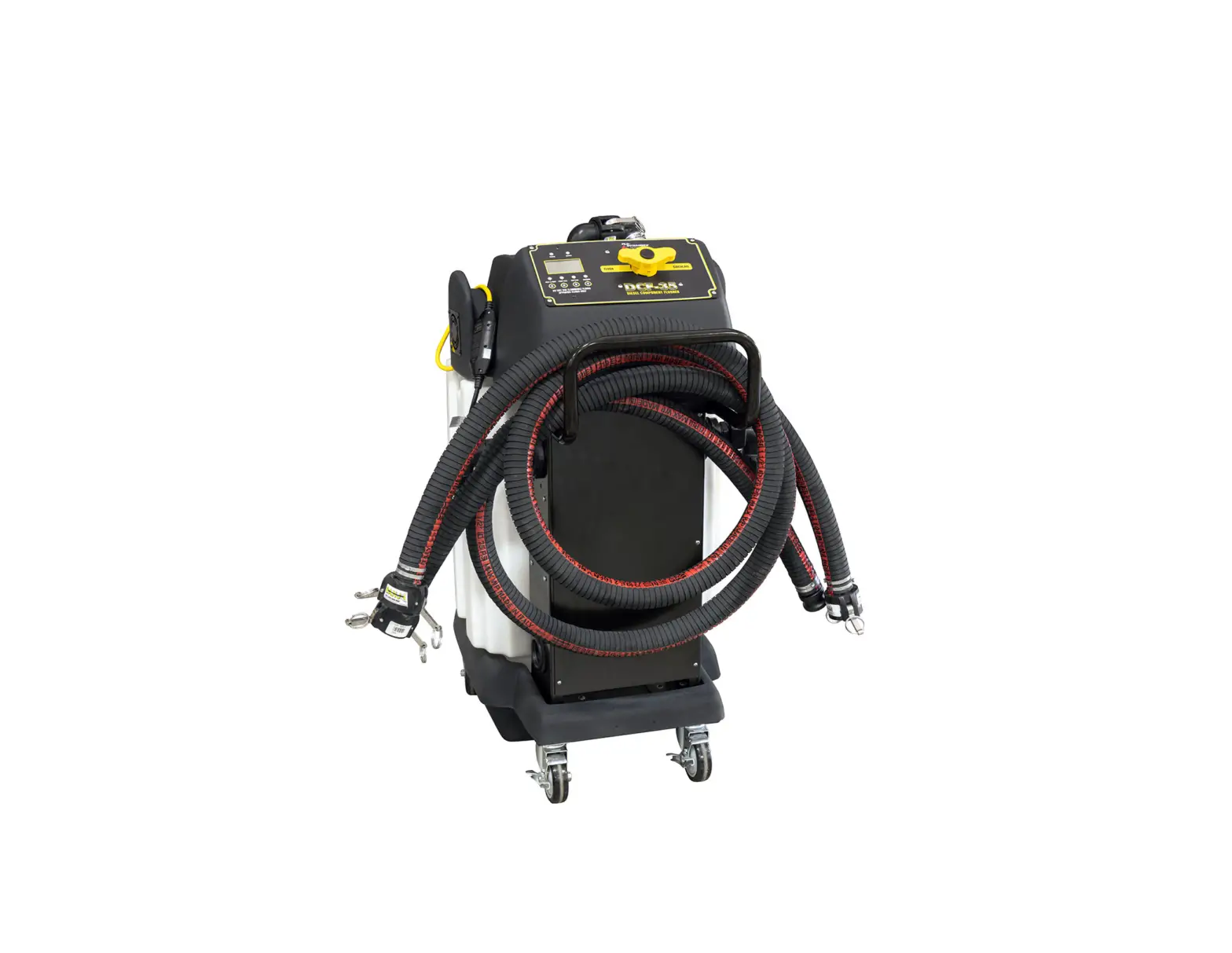
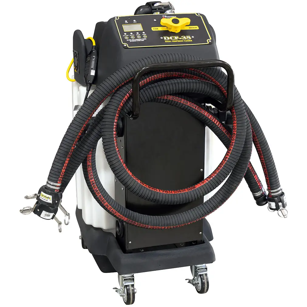
FLO-DYNAMICS DCF-35 Diesel Component Flusher
OPERATION
SAFETY RECOMMENDATIONS
Use extreme safety measures when working around a running engine, pressurized storage vessels, and automotive chemicals.
Always block the vehicle’s drive wheels.
Ventilate the vehicle’s exhaust if engine will be started.
Always wear safety glasses, protective clothing, and gloves.
WARNING: Use only the approved Flo-Dynamics FLOCOR Flo Carbon & Oil Remover (P/N 40201131). Do not use any other non-approved cleaners or any cleaner that is flammable to prevent a health hazard or personal injury
FLUSHING PROCEDURES
Inspect engine compartment and visible components to be flushed for signs of damage or unusual wear.
FLUSHING PROCEDURES:
A.) COMPONENT FLUSHING – CAC (Charge Air Coolers), Cooling System & Components
B.) FORD 6.7L EGR VALVE AND COOLER FLUSHING
PRESSURE CHECKING A COMPONENT
| NOTE: Pressure checking an EGR valve and cooler assembly is not required. If applicable, pressure testing a component can be performed with the component installed on the vehicle. Disconnect inlet and outlet hoses from the component being cleaned. Connect blocked pressure adapter to one outlet and pressure adapter with gauge and regulator to the other. Secure safety cables on each adapter to vehicle or component to prevent becoming airborne if blown off. Connect shop air to pressure gauge, make sure valve is open, and adjust to manufacturer’s pressure check PSI rate or 15 PSI. CAUTION: Do not exceed 25 PSI on any component. Turn valve off and observe amount of pressure decay, noting any decrease on the gauge. Check with manufacturer on the leakage rate that is within their acceptable limits of the component being checked. If component leakage is acceptable, release pressure and remove safety cables and adapters. Proceed to Procedure “A” – Performing a Component Flush. | 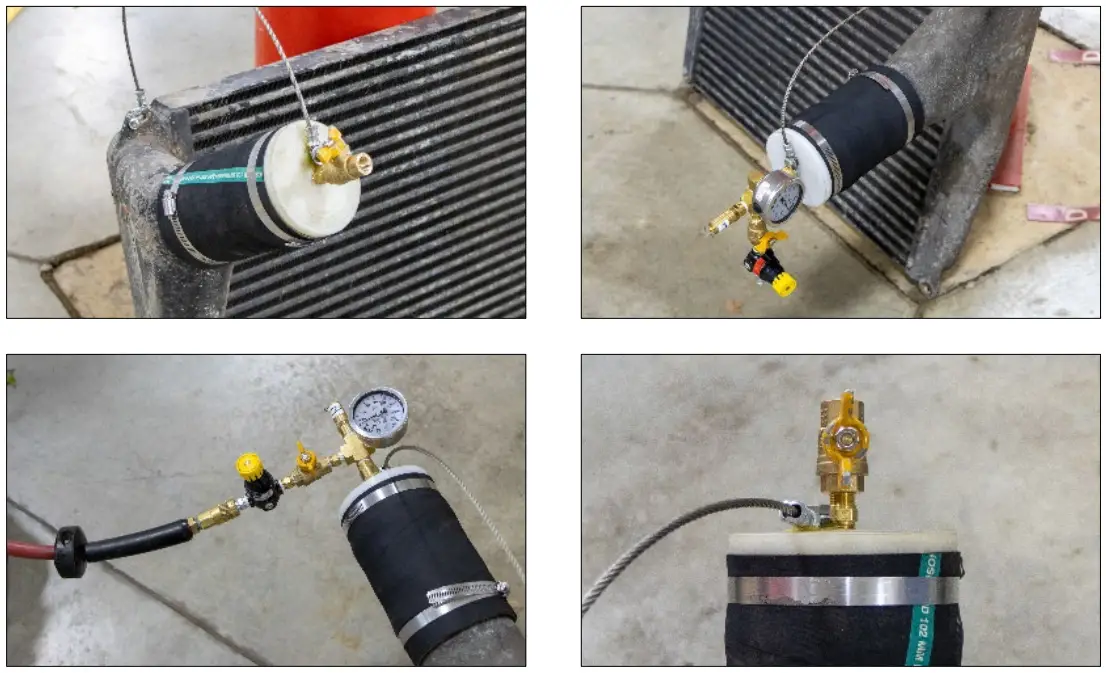 |
PROCEDURE “A” – PERFORMING A COMPONENT FLUSH
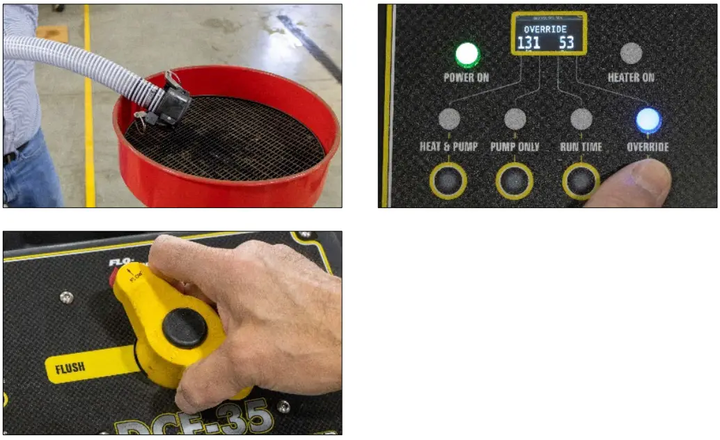
| Once a component has passed the pressure check procedure, perform the following: Add 10 gallons of water and 1 gallon of FLOCOR Carbon & Oil Remover (P/N 40201131) to the DCF-35 reservoir. Position the Flow Control Valve to CIRCULATE mode. Plug the DCF-35’s power cord into an electrical outlet. The green power light will illuminate. Press the RUN TIME button to select CONTINUOUS. Press the HEAT & PUMP button to circulate and heat reservoir to 130°F while adapters are being installed. | 
|
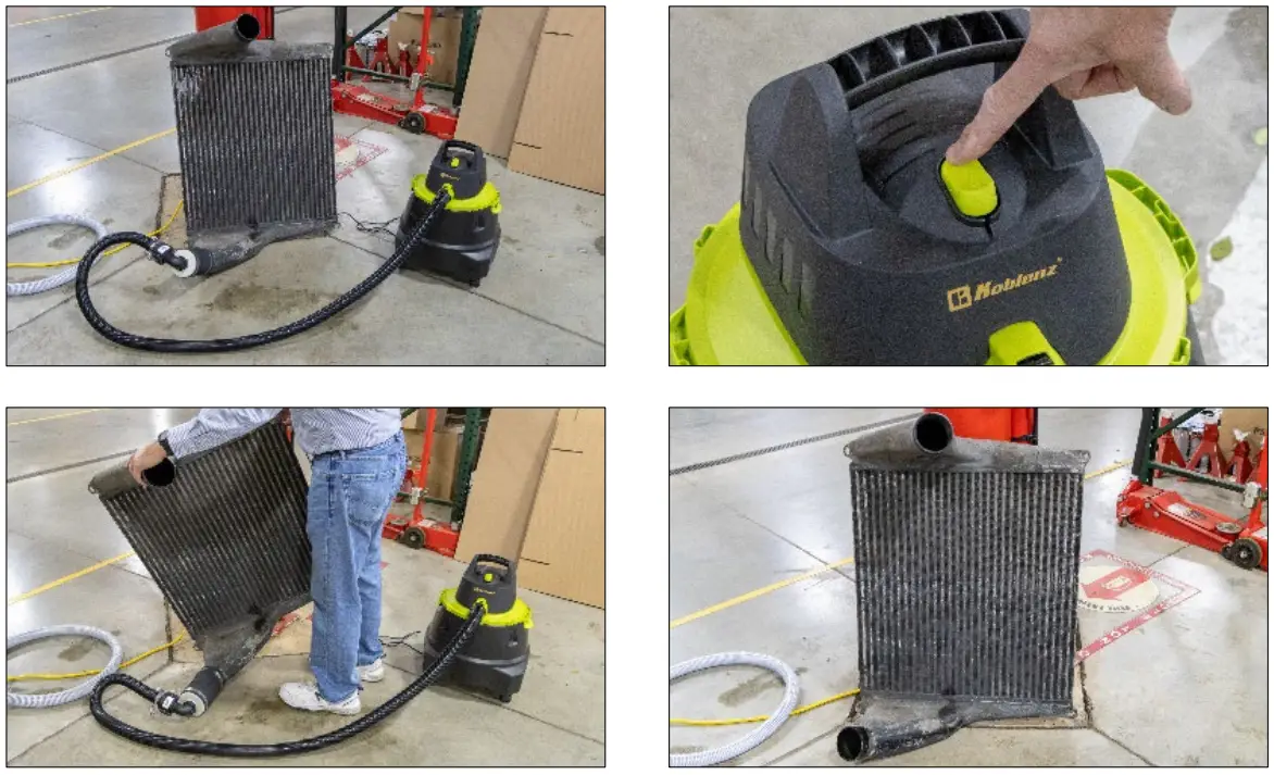
| Position component with flow outlet on top and inlet on the bottom. Using the DCF-35 CAC Pressure & Flushing Adapter Kit (P/N 40100104 KIT), install adapters to component or system being flushed. Connect the DCF-35 outlet service hose (left side) to the component’s outlet adapter (top) and the DCF-35 inlet service hose (right side) to the component’s inlet adapter (bottom). | 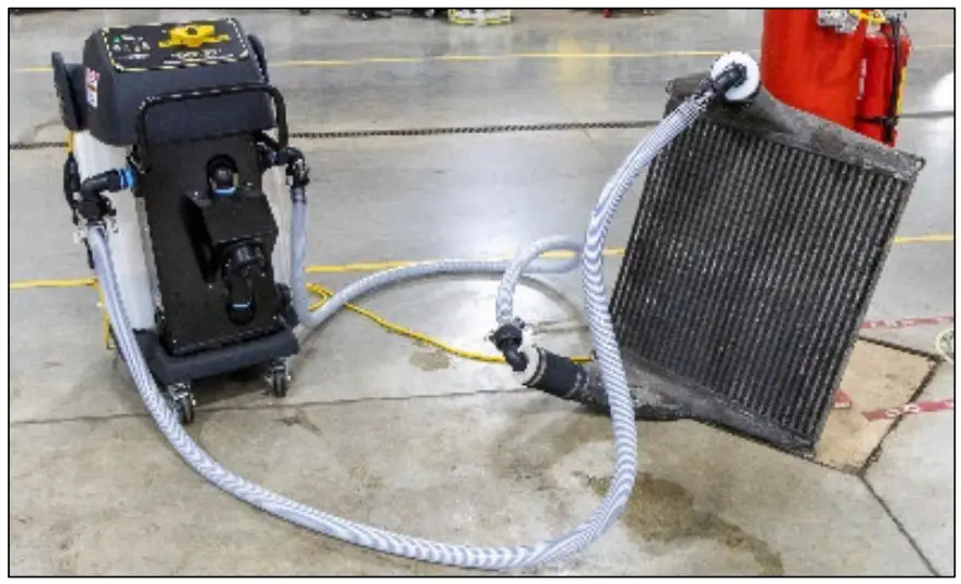 |
| When the red HEATER ON light turns off, the reservoir temperature is at 130°F and you are ready to flush. Press the RUN TIME button to select desired flush time. Position the Flow Control Valve to FLUSH mode. When the run time has elapsed, the DCF-35 will turn off and the RUN TIME light will flash. Position the Flow Control Valve to CIRCULATE mode. | 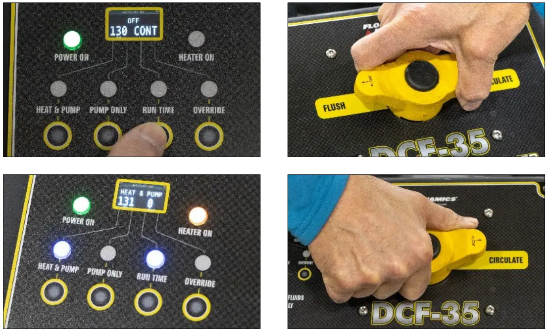 |
| Position the component on its side with the DCF-35 outlet service hose on the top. Slowly remove the top service hose, which is connected to the DCF-35 outlet, and drain into a suitable container. Connect a wet/dry vac hose to the blow port, and the other end to the component’s top adapter. Turn on vacuum to blow cleaning fluid back into DCF-35 until air begins to enter DCF-35 reservoir, then turn off. CAUTION: To prevent cleaner foaming in reservoir do not continue to blow back into DCF-35 reservoir after component has been emptied and bubbles begin agitating cleaner. | 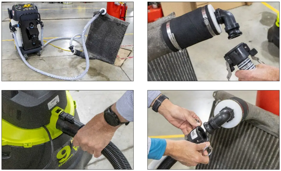
|
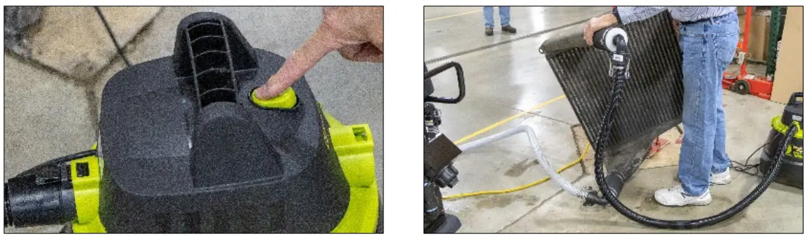
| Remove DCF-35 inlet service hose from bottom component adapter. Switch vacuum hose from the blow port to the suction port and connect the other end to the bottom component adapter. Remove top adapter to increase air flow. Turn on vacuum to air purge and position the component so the bottom adapter is at the lowest point to capture all the cleaning fluid. Air purge with vacuum for 10-20 minutes or until all moisture droplets are removed from component being cleaned. Inspect component being flushed for cleanliness and if needed select a new run time and repeat until component is at the desired cleanliness. Remove adapters. Component is ready to be re-installed. Empty wet/dry vac into a suitable container. NOTE: Dispose of used cleaner in compliance with local guidelines only. Do not dispose into local drains. See “ADDITIONAL FUNCTIONS” draining reservoir procedures to drain reservoir. | 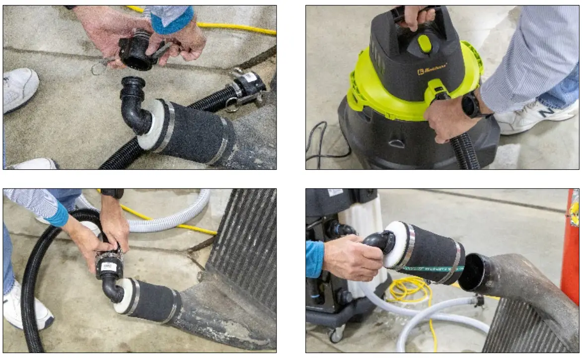
|

PROCEDURE “B” – FORD 6.7L EGR VALVE AND COOLER FLUSHING
| CAUTION: When flushing a Ford 6.7L EGR valve and cooler, it is very important to adhere to the following: FORD DEALERSHIPS NON-FORD DEALERSHIPS WARNING: To perform a Ford 6.7L EGR cooler and valve cleaning, the Ford 6.7L EGR Cooler Cleaning Kit (P/N 40100130) must be used to connect, remove, and air purge any remaining liquid in the EGR cooler assembly. THIS IS A MUST SINCE THERE IS STILL APPROXIMENTLY 1 QT OF LIQUID IN THE EGR VALVE AND COOLER ASSEMBLY. FAILURE TO REMOVE REMAINING LIQUID COULD RESULT IN ENGINE DAMAGE FROM INGESTING CLEANING FLUID. | |
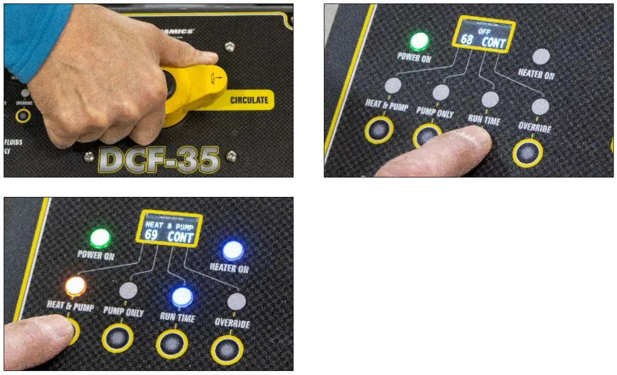
| Drive vehicle and note if any warning lights are illuminating on instrument cluster and check for any existing diagnostic codes using a Ford IDS or similar. Add 10 gallons of water and 1 gallon of FLOCOR Carbon & Oil Remover (P/N 40201131) to DCF-35 reservoir. Position the Flow Control Valve to CIRCULATE mode. Plug the DCF-35’s power cord into an electrical outlet. The green power light will illuminate. Press the RUN TIME button to select CONTINUOUS. Press the HEAT & PUMP button to circulate and heat the reservoir to 130°F while the EGR tubes are being removed and adapter hoses installed. | 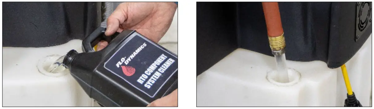
|
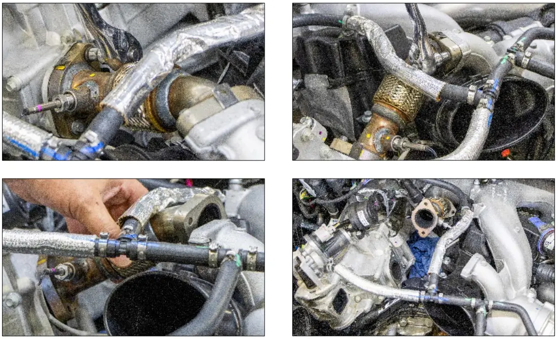
| Remove zip-tube to enable access to EGR cooler inlet and outlet tubes. Remove inlet and outlet EGR cooler tubes, noting the above CAUTION on removing bolts.Identifying the EGR cooler inlet and outlet ports: – EGR inlet is the square port at EGR valve – EGR outlet is the round port CAUTION: EGR outlet tube metal gaskets can have sharp edges. Use caution when handling. Inspect amount of carbon build-up by using a borescope or viewing through the outlet port or by looking at the bottom corner of the EGR cooler through the round outlet port with an inspection light. Suggested EGR cooler flush times: | 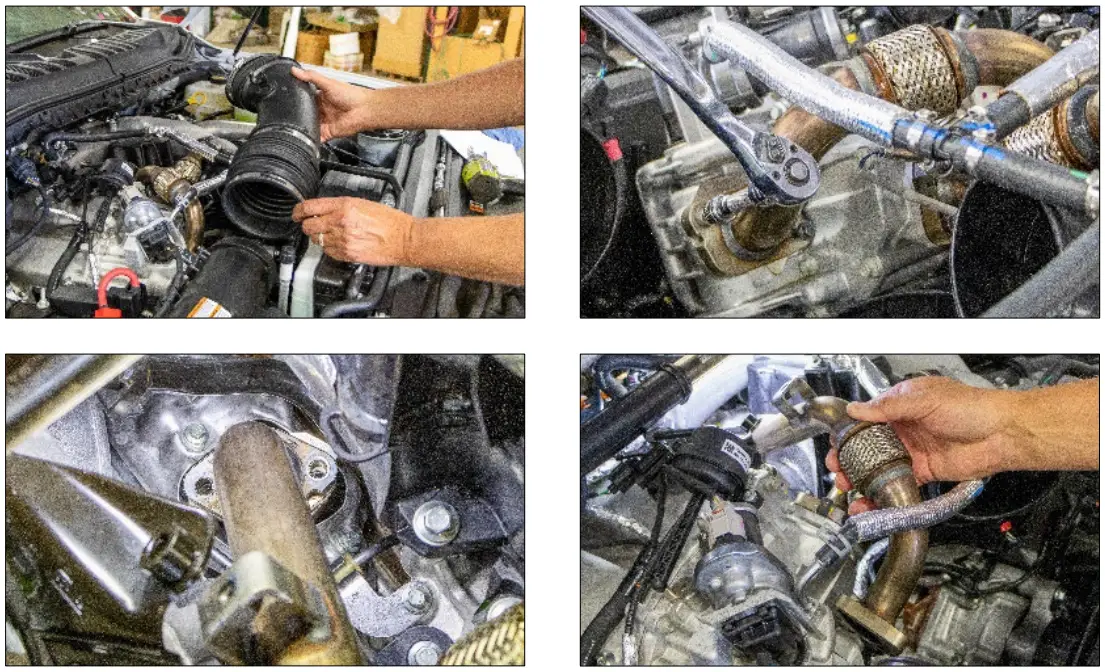
|
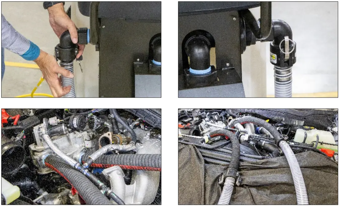
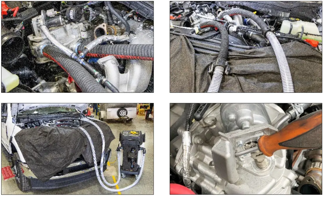
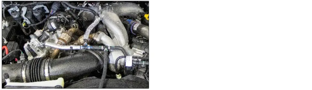
| Secure the white service hoses to the DCF-35 using the provided camlocks. Install the Ford 6.7L EGR inlet and outlet adapter hoses onto the EGR cooler. Connect the white DCF-35 outlet service hose (left side) to the black EGR outlet port adapter hose. Connect the white DCF-35 inlet service hose (right side) to the black EGR inlet port adapter hose.Open the EGR valve using one of the following methods:
| 
|
| When the red HEATER ON light turns off, the reservoir temperature is at 130°F and you are ready to flush. Press the RUN TIME button to select the desired flush time as noted when inspecting outlet cooler port above. Position the Flow Control Valve to FLUSH mode. When run time has elapsed, the DCF-35 will turn off and the RUN TIME light will flash. Position the Flow Control Valve to CIRCULATE mode. | 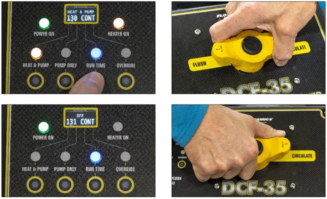 |
| NOTE: When separating camlock connectors, keep hose elevated and drain into a suitable container. Slowly release the camlocks on the DCF-35 outlet service hose at the EGR outlet port adapter hose. Keep the hose elevated and drain the remaining liquid into a suitable container. Release the camlocks on the DCF 35 inlet service hose at the EGR inlet port adapter hose. Keep the hose elevated and drain the remaining liquid into a suitable container. Use the following shop-vac procedure to drain the EGR cooler and adapter hoses. | 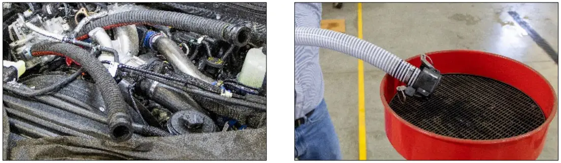 |
| SHOP-VAC DRAINING AND AIR PURGE PROCEDURE – MUST PERFORM! WARNING: FAILURE TO PERFORM THE SHOP-VAC DRAINING AND VACUUM PURGE PROCEDURE COULD RESULT IN ENGINE FAILURE DUE TO INGESTING REMAINING CLEANER IN EGR COOLER. Connect the suction port of a wet/dry vac to the EGR inlet port adapter hose and turn on for 30 seconds to initially remove cleaning fluid from EGR cooler and hoses. | 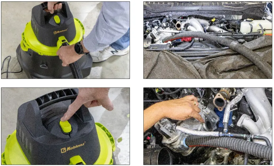
|
ADDITIONAL FUNCTIONS
DRAINING RESERVOIR USING PUMP
| CAUTION: The DCF-35 has a high flow pump. With the Flow Control Valve fully open in FLUSH mode, the DCF35 will pump at a rate of 45 GPM. Plug the DCF-35’s power cord into an electrical outlet. Connect a service hose to the DCF 35’s outlet connection (left side). Position the Flow Control Valve to CIRCULATE mode. Place the service hose into a suitable waste container. Start the pump by pressing PUMP ONLY and OVERRIDE to disable the low fluid shutoff. Slowly move the Flow Control Valve to the FLUSH position to begin directing flow to the service hose placed in the waste container. When the flow stops, the reservoir is emptied to the lowest level possible using the pump. To drain further, see Complete Reservoir Draining or Flushing procedure.NOTE: Dispose of used cleaner in compliance with local guidelines only. Do not dispose into local drains. | 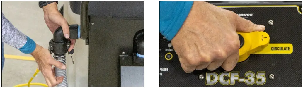
|
COMPLETE RESERVOIR DRAINING OR FLUSHING
| CAUTION: When connecting the supplied drain hose, the reservoir will begin draining immediately. This procedure should only be used after performing the Drain Reservoir Using Pump procedure and with the DCF-35 unplugged. Have a suitable container ready to capture the remaining cleaner when connecting the drain hose, and drain the reservoir.NOTE: Dispose of used cleaner in compliance with local guidelines only. Do not dispose into local drains. | 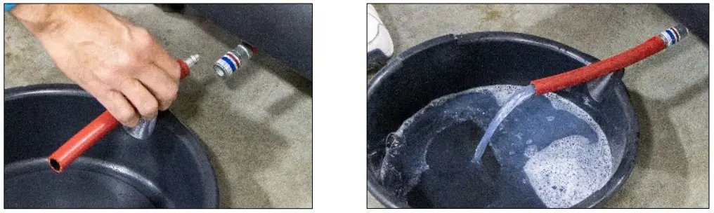 |