
PlantPRO 59130 Drum Pump Set
Product Information
- Product Name: Drum & Container Pumps
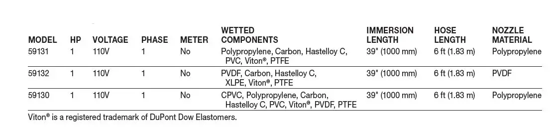
- Model Numbers: Complete Drum Pump Packages 59130, 59131 & 59132; Replacement Electric Motors 59133 & 59134; Replacement Pump Tubes 59135, 59136 & 59137
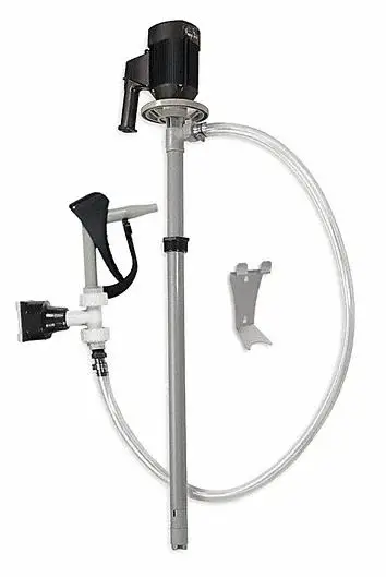
- Description: PlantPRO Drum Pumps are designed for transferring a variety of materials from 55-gallon drums and tanks. The pumps are available in different models, each suitablefor specific applications. It is important to ensure that the pump materials of construction are compatible with the materials being pumped.
Product Usage Instructions
- Handle cartons with care to avoid damage during unpacking.
- Inspect the contents of the carton for any damage or missing parts.
- Read and understand all safety precautions and operating instructions before operating the pump.
- Wear suitable protective clothing, including a face mask, safety shield or goggles, gloves, apron, and safety shoes.
- Verify that the materials being pumped are compatible with the pump’s wetted components.
- Follow all federal, state, and local safety codes.
- Ensure that the motor voltage matches the proper electrical supply.
- Before plugging the motor into the power supply, make sure the motor switch is in the OFF position. Confirm all pump connections are properly tightened.
- Run clean water through the pump initially to familiarize yourself with its operation, flow rate, discharge pressure, and motor speed.
- Securely fasten the discharge hose to the receiving vessel before starting the pump to prevent splashing.
- Never leave the pump unattended during operation.
- Do not submerge the motor in any liquid.
- After using the pump, flush it by pumping water or an appropriate cleaning solution. Do not use flammable or combustible cleaning solutions.
- Do not carry the motor by the power cord.
- Rinse the pump thoroughly and hang it on a wall bracket or store the pump tube in an upright and vertical position. Do not store the pump in a container or drum.
- WARNING: The speed control switch should not be used as the main ON/OFF switch. Using it as such can cause premature failure of the potentiometer. The speed control switch does not cut power to the motor, so inadvertent activation can result in injury or death if the motor is not properly attended and secured. (Applies only to models 59133 and 59134)
- WARNING: Drum Pumps are intended for intermittent duty use. Do not operate the pump for more than 30 minutes at a time. After 30 minutes of use, allow the pump to cool down for 30 minutes. The maximum operating time depends on factors such as ambient temperature, viscosity, specific gravity, and discharge plumbing configuration.
Description
PlantPRO Drum Pumps transfer a variety of materials from 55-gallon drums and tanks. Several different pumps are available, each designed for specific applications. Before operating, please confirm that the pump’s materials of construction are suitable for the application.
Unpacking
Cartons should be handled with care to avoid damage from dropping, etc. After unpacking, inspect carefully for any damage that may have occurred during transit. Check for loose, damaged or missing parts.
General Safety Information
The responsibility for safe assembly, installation, and operation ultimately rests with the operator. Read and understand ALL safety precautions and operating instructions before operation. Careless pump operation can result in serious injury.
- Before operating the pump, read and understand these operating instructions.
- The operator should wear suitable protective clothing, including: face mask, safety shield or goggles, gloves, apron, and safety shoes.
- Before operating, verify the materials being pumped are compatible with the pump’s wetted components.
- All federal, state and local safety codes should be followed.
- Verify that the motor voltage corresponds to proper electrical supply.
- Before plugging motor into power supply, make sure the motor switch is in the OFF position. Before operation, confirm all pump connections are properly tightened
- First pump clean water in order to familiarize yourself with the pump’s operation, flow rate, discharge pressure and motor speed.
- Before starting the pump, confirm the discharge hose is securely fastened to the receiving vessel in order to prevent splashing.
- Never leave pump unattended during operation.
- Do not submerge the motor in any liquid.
- When finished using the pump, flush the pump by pumping water or an appropriate cleaning solution. Do not use flammable or combustible cleaning solutions.
- Never carry the motor by the power cord.
- Never store pump in a container or drum. Always rinse pump thoroughly and hang on wall bracket or ensure pump tube is stored in an upright and vertical position.
WARNING: The speed control should not be used as the main ON/OFF switch. Using the speed control switch in this manner causes excessive wear to the potentiometer and may result in premature failure. The use of the speed control switch does not cut power to the motor and inadvertent activation could result in injury or death if the motor is activated when not properly attended and secured (only applies to 59133 and 59134).
WARNING: Drum Pumps are intended for intermittent duty use. Factory recommendation is that the pumps are NOT operated for more than 30 minutes at one time. After30 minutes of use, the pump will need a 30 minute cool down period. The maximum operating time depends upon several factors including (but not limited to) ambient temperature, viscosity, specific gravity, and the discharge plumbing configuration.
Complete Drum Pump Packages
Specifications
Assembly
- Remove the pump and motor from packaging.
- Inspect all contents for damage.
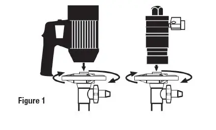
- Couple the motor to the pump tube by using the Hand Wheel (see Figure 1).

Operation
- Once the pump is fully assembled and all connections are securely fastened, insert the pump into the drum or tank.
- Turn the motor switch to the “ON” position or open air inlet valve.
- After use, clean the pump and store vertically.
Maintenance
DISASSEMBLY/CLEANING PROCEDURES
- In order to clean a majority of the residue from the pump tube, immerse the pump into a 55-gallon drum of water. Allow the pump to circulate the water for 3 minutes.
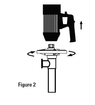
- For a more thorough cleaning, remove the motor from the pump tube by loosening the hand wheel (see Figure 2).

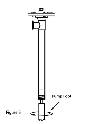
- Remove the pump foot (see Figure 3)

- NOTE: Remove pump foot by turning clockwise.
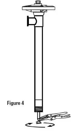
- While holding the drive shaft with pliers (factory suggests using grip-locks to avoid scarring shaft), remove the impeller by turning counterclockwise (see Figure 4).

- NOTE: Use grip lock pliers to hold shaft while removing impeller.
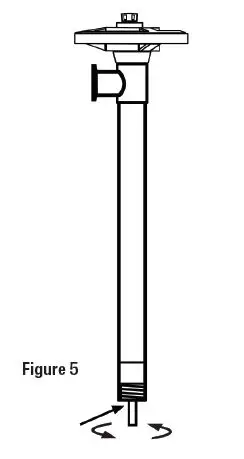
- Remove the Pump Housing (see Figure 5).

- NOTE: Remove pump housing by turning clockwise.
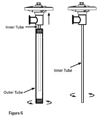
- For plastic and aluminum models, remove outer tube and inner tube from discharge housing by turning clockwise (see Figure 6).

- Remove pump coupling (MFR # 1004) from drive shaft by turning counterclockwise (see Figure 7).
- NOTE: Use grip-lock pliers to hold shaft while removing coupling.

- NOTE: Use grip-lock pliers to hold shaft while removing coupling.
- Pull drive shaft straight down, removing it from the discharge housing or connection flange while inserting a screwdriver through bearing unit (MFR # 1038) (see Figure 8).
- NOTE: Ensure screwdriver is maintained inside bearing unit so spacer and seal are stationary and aligned properly for reassembly.
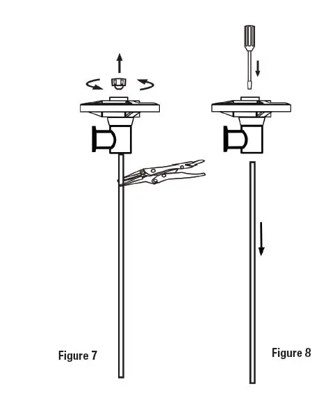
WARNING: When replacing the drive shaft in the bearing unit (MFR # 1038) during reassembly, make sure the driveshaft is inserted through the spacer in between the bearings inside the bearing unit. Failure to do so could cause the bearing unit to prematurely fail.
Electric Drum Pump Motors
Specifications
| MODEL | VOLTAGE | AMPS | WATTS | HP | PHASE | HZ | ENCLOSURE | VARIABLE SPEED | HAZARDOUS DUTY | SHIP WT., LBS (KG) |
| 59133† | 110V | 8.5 | 825 | 1 | 1 | 50-60 | 0DP (IP44) | Y | N | 9.0 (4.0) |
| 59134† | 110V | 8.5 | 825 | 1 | 1 | 50-60 | TEFC (IP54) | Y | N | 12.7 (5.7) |
† Motor has thermal overload protection which stops pump in case of overload. Immediately switch the motor to the OFF position “0”, and allow motor to cool down. Warning: Motor will automatically start after cooling down if switch is left in the ON position “1”.
Parts List
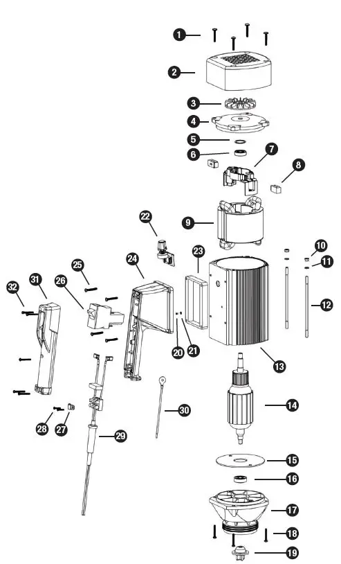
59133 Electric Motor Spare Parts List
| REF # DESCRIPTION MFR # QTY | |||
| 1 | Screw, Motor Cover/Lower Housing | 8130P | 8 |
| 2 | Motor Cover | 8000 | 1 |
| 3 | Wave Washer | 8125 | 1 |
| 4 | Bearing, Upper | 8331 | 1 |
| 5 | Brush Holder | 8508 | 1 |
| 6 | Carbon Brush, 110V/220V | 8509* | 2 |
| 7 | Stator | 1 | |
| 110V | 8503 | ||
| 220V | 8702 | ||
| 8 | Hexagon Nut | 8448 | 2 |
| 9 | Lock Washer | 8071 | 2 |
| 10 | Rod Connector | 8506 | 2 |
| 11 | Pressure Spring | 8507 | 2 |
| 12 | Motor Housing | 8510P | 1 |
| 13 | Armature | 1 | |
| 110V | 8502 | ||
| 220V | 8701 | ||
| 14 | Guide Disc | 8504 | 1 |
| 15 | Fan | 8512 | 1 |
| 16 | Bearing, Lower | 8126 | 1 |
| 17 | Lower Housing | 8100 | 1 |
| 18 | Motor Coupling | 8333* | 1 |
| 19 | Speed Potentiometer | 1 | |
| 110V | 9803 | ||
| 220V | 9804 | ||
| 20 | Gasket | 1 | |
| 110V | 8167 | ||
| 220V | 8167LVR | ||
| 21 | Switch Housing | 1 | |
| Fixed Speed | 8001 | ||
| Variable Speed | 8010 | ||
| 22 | Screw, Switch Housing | 4 | |
| 110V | 8131 | ||
| 220V | 8131LVR | ||
| 23 | Overload Switch | 1 | |
| 110V | 8611 | ||
| 220V (w/ Low Voltage Release) | 8704LVR | ||
| 220V (w/o Low Voltage Release) | 8704 | ||
| 24 | Cable Clamp | 8001-1 | 1 |
| 25 | Screw, Cable Clamp | 8001-2 | 2 |
| 26 | Power Cord 1 | ||
| 110V | 8360-KIT | ||
| 220V | 8705-KIT | ||
| 27 | Earthing Lead | 8183 | 1 |
| 28 | Switch Cover | 8002 | 1 |
| 29 | Screw, Switch Cover | 8221 | 5 |
| N/A | Repair Kit* (*Includes Items 6 & 18) | 1 | |
| 110V/220V | 9055 | ||

59134 Electric Motor Spare Parts List
| REF # DESCRIPTION MFR # QTY | |||
| 1 | Screw, Motor Cover | 3130 | 4 |
| 2 | Motor Cover | 3000 | 1 |
| 3 | Fan | 3512 | 1 |
| 4 | Bearing Cover | 3511 | 1 |
| 5 | Wave Washer | 8125 | 1 |
| 6 | Bearing, Upper | 8331 | 1 |
| 7 | Brush Holder | 8508 | 1 |
| 8 | Carbon Brush, 110V/220V | 8509* | 2 |
| 9 | Stator | 1 | |
| 110V | 3503 | ||
| 220V | 3702 | ||
| 10 | Hexagon Nut | 8448 | 2 |
| 11 | Lock Washer | 8071 | 2 |
| 12 | Rod Connector | 3703 | 2 |
| 13 | Motor Housing | 3510 | 1 |
| 14 | Armature | 1 | |
| 110V | 3502 | ||
| 220V | 3701 | ||
| 15 | Guide Disc | 3504 | 1 |
| 16 | Bearing, Lower | 8126 | 1 |
| 17 | Lower Housing | 8100 | 1 |
| 18 | Screw, Lower Housing | 8130 | 4 |
| 19 | Motor Coupling | 8333* | 1 |
| 20 | Ground Screw | 8162 | 1 |
| 21 | Star Washer | 8511 | 1 |
| 22 | Speed Potentiometer | 1 | |
| 110V | 9803 | ||
| 220V | 9804 | ||
| 23 | Gasket | 1 | |
| 110V | 8167 | ||
| 220V | 8167LVR | ||
| 24 | Switch Housing | 1 | |
| Fixed Speed | 8001 | ||
| Variable Speed | 8010 | ||
| 25 | Screw, Switch Housing | 4 | |
| 110V | 8131 | ||
| 220V | 8131LVR | ||
| 26 | Overload Switch | 1 | |
| 110V | 8611 | ||
| 220V (w/ Low Voltage Release) | 8704LVR | ||
| 220V (w/o Low Voltage Release) | 8704 | ||
| 27 | Cable Clamp | 8001-1 | 1 |
| 28 | Screw, Cable Clamp | 8001-2 | 2 |
| 29 | Power Cord | 1 | |
| 110V | 8360-KIT | ||
| 220V | 8705-KIT | ||
| 30 | Earthing Lead | 8183 | 1 |
| 31 | Switch Cover | 8002 | 1 |
| 32 | Screw, Switch Cover | 8221 | 5 |
| N/A | Repair Kit* (*Includes Items 8 & 19) | 1 | |
| 110V/220V | 9055 | ||
Replacement Pump Tubes
Specifications
| MODEL | MATERIAL OF CONSTRUCTION | MAX LIQUID TEMPERATURE | WETTED MATERIALS | MAXIMUM FLOW RATE | DISCHARGE PRESSURE |
| 59135 | CPVC | 190º F (90°C) | CPVC, Carbon, Hastelloy C, PVDF, PTFE | 35 gpm (132 L/min) | 16 psi (1.1 bar) |
| 59136 | Polypropylene | 130º F (55°C) | PP, Carbon, Hastelloy C, PTFE | 35 gpm (132 L/min) | 16 psi (1.1 bar) |
| 59137 | PVDF (Kynar®) | 175º F (80°C) | PVDF, Carbon, Hastelloy C, PTFE | 35 gpm (132 L/min) | 16 psi (1.1 bar) |
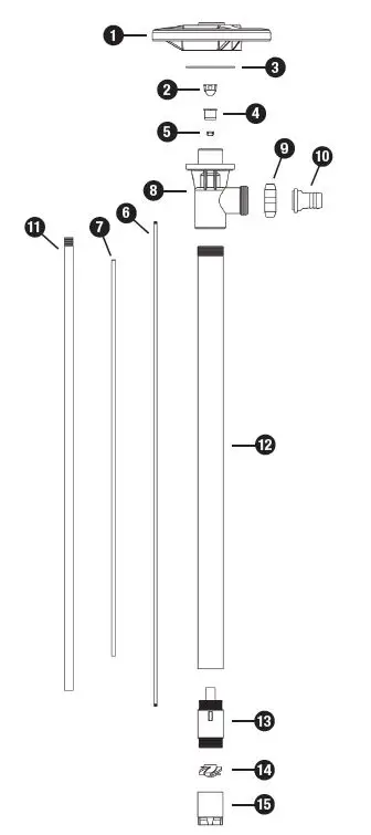
Pump Tube Spare Parts List
These pump tubes should not be used to pump flammables.
| REF # DESCRIPTION MFR # MFR # MFR # QTY for 59136 for 59135 for 59137 | |||||
| 1 | Hand Wheel, Polypropylene | 1842 | 1842 | 1842 | 1 |
| 2 | Pump Coupling, Nylon | 1004* | 1004* | 1004* | 1 |
| 3 | Snap Ring, Steel | 1508 | 1508 | 1508 | 1 |
| 4 | Bearing Unit Assembly | 1038* | 1038* | 1038* | 1 |
| 5 | V-Seal | 1 | |||
| Viton® | 1000 | — | — | ||
| PTFE | — | 4000 | 4000 | ||
| 6 | Drive Shaft, Hastelloy, 39″ (1000 mm) | 1544 | 1544 | 1544 | 1 |
| 7 | Guide Sleeve, PTFE, 39″ (1000 mm) | 1514 | 1514 | 1514 | 1 |
| 8 | Discharge Housing | 1028 | 5028 | 4028 | 1 |
| 9 | Wing Nut | 1106 | 5106 | 4106 | 1 |
| 10 | Hose Barb | 1 | |||
| 0.75″ (19 mm) | 1051 | 5051 | 4051 | ||
| 1″ (25 mm) | 1082 | 5082 | 4082 | ||
| 11 | Inner Tube, 39″ (1000 mm) | 1601 | 5601 | 4601 | 1 |
| 12 | Outer Tube, 39″ (1000 mm) | 1603 | 5603 | 4603 | 1 |
| 13 | Pump Housing (Includes Carbon Bushing) | 1524* | 5524* | 4607* | 1 |
| 14 | Rotor/Impeller | 1 | |||
| High Volume Rotor | 1608* | 5608* | 4608* | ||
| High Pressure Impeller | 4608HH | 4608HH | 4608HH | ||
| 15 | Pump Foot | 1 | |||
| High Volume | 1609* | 5609* | 4609* | ||
| High Pressure | 1609HH | 5609HH | 4609HH | ||
| N/A | Repair Kit* (*includes items 2, 4, 13, 14 & 15) | 9050 | 9052 | 9051 | 1 |
Warranty
Three year limited warranty
Standard Pump, Inc. warrants, subject to the conditions below, through either Standard Pump, Inc., its subsidiaries, or its authorized distributors, to repair or replace free of charge, including labor, any part of this equipment which fails within three years of delivery of the product to the end user. Such failure must have occurred because of defect in material or workmanship and not as a result of operation of the equipment other than in accordance with the instructions given in this material. Specific exceptions include:
- Consumable items such as motor brushes, bearings, couplings and impellers. (Motor brushes typically have a life span of approximately 250 hours. This will vary with the manner in which the motor is used.)
Conditions of exceptions include:
- Equipment must be returned by prepaid carriage to Standard Pump, Inc., its subsidiary or authorized distributor.
- All repairs, modifications must have been made by or with express written permission by Standard Pump, Inc., its subsidiary or authorized distributor.
- Equipment which have been abused, misused, or subject to malicious or accidental damage or electrical surge are excluded.
Warranties purporting to be on behalf of Standard Pump, Inc., made by any person, including representatives of Standard Pump, Inc., its subsidiaries, or its distributors, which do not fall within the terms of this warranty shall not be binding upon Standard Pump, Inc., unless expressly approved in writing by a Director or Manager of Standard Pump, Inc. Information for returning pumps Equipment which has been contaminated with, or exposed to, bodily fluids, toxic chemicals or any other substance hazardous to health must be decontaminated before it is returned to Standard Pump, Inc, or its distributor. A returned goods authorization number (RGA #) issued by Standard Pump, Inc., its subsidiary or authorized distributor, must be included with the returned equipment. The RGA # is required if the equipment has been used. If the equipment hasbeen used, the fluids that have been in contact with the pump and the cleaning procedure must be specified along with a a statement that the equipment has been decontaminated.
CONTACT
STANDARD PUMP
- 1610 Satellite Blvd. Suite D, Duluth, Georgia 30097 USA 866.558.8611
- Phone 770.307.1003
- Fax 770.307.1009
- [email protected].
- www.standardpump.com.
- Complete Drum Pump Packages
59130, 59131 & 59132 - Replacement Electric Motor s
5 9 13 3 & 5 9 13 4 - Replacement Pump Tubes
59135, 59136 & 59137 - P.O. Box 9004, Gurnee, IL 60031-9004
- Phone 847.689.3000
- Fax 847.689.3002
- email [email protected].
- usabluebook.com.


