![]()
Installation & Operation Instructions
Phone: 1-888-967-5224
Website: workaci.com
GENERAL INFORMATION
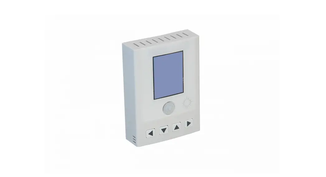
“Particulate matter (PM) is the general term used to describe solid particles and liquid droplets found in the air. The PM series of transmitters are designed to measure Particulates that include smoke, smog, bacteria, fine dust, liquid droplets, and report the total particle concentration of the monitored environment. ACI’s PM series transmitters utilize a laser particulate matter sensor, that is offered in two different measuring ranges. The PM series transmitters operate on a laser scattering principle, utilizing a fan sampling method.
The PM2.5 is designed to detect Particles less than 2.5 pm in diameter. The PM10 is designed to detect Particles less than 10 pm in diameter.
The sensor has two jumper selectable working modes for monitoring PM. The Normal Mode monitors the environment continuously and Auto Mode reduces the measuring time to extend service life. The sensor is sent default in Auto Mode.
IMPORTANT PRECAUTIONS
- This product uses a laser particulate matter sensor. It is strictly prohibited to be disassembled. It is dangerous if the human body is exposed to the laser directly.
- If the environment exceeds the measurement range for an extended period, it may lead to a decrease of measurement accuracy.
- The performance of the sensor may be decreased due to excessive dust and oil mist, etc. in extreme environments. (ie: high humidity, high temperature)
- Avoid strong light in the housing.
- Avoid vibration.
MOUNTING INSTRUCTIONS
For optimal temperature readings, follow these tips:
- Avoid air registers, diffusers, vents, and windows
- Avoid confined areas such as shelves, closed cabinets, closets, and behind curtains.
- Eliminate and seal all wall and conduit penetrations. Air migration from wall cavities may alter readings.
- Do not install near heat sources. eg: lamps, radiators, direct sunlight, copiers, chimney walls, walls concealing hot-water pipes
FIGURE 1: ENCLOSURE DIMENSIONS
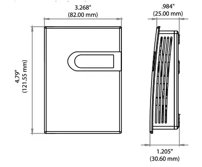
FIGURE 2: OPENING COVER
Separate the cover from the base by inserting a flat head screwdriver into the top slot marked “OPEN”. Pry the cover forward.
Attach the base directly to the wall or to a standard 2″x 4″ junction box using (2) #6-32 x 1″ screws.
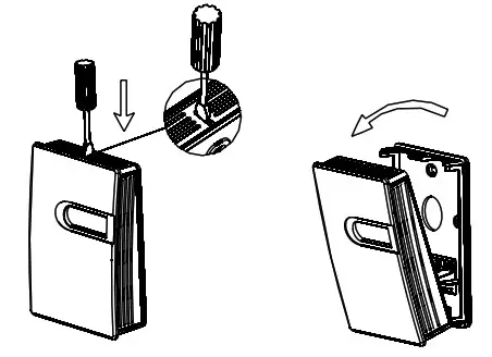
FIGURE 3: BACKPLATE
Refer to the wiring instructions to make necessary connections. After wiring, attach the cover to the base by snapping the top of the cover on first and then the bottom.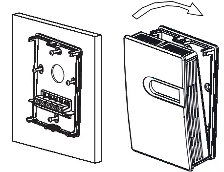
Take care when mounting. Check local code for mounting height requirements. Typical mounting heights are 48-6011.22-1.52m) off the ground and at least 1.51(0.5m) from the adjacent wall. The sensor should be mounted in an area where air circulation is well mixed, and not blocked by obstructions.
WIRING INSTRUCTIONS PRECAUTIONS
- DO NOT RUN THE WIRING IN ANY CONDUIT WITH LINE VOLTAGE(24/120/230VAC).
- Remove power before wiring. Never connect or disconnect wiring with power applied.
- It is recommended that you use an isolated UL-listed Class 2 transformer when powering the unit with 24 VAC. Failure to wire the devices with the correct polarity when sharing transformers may result in damage to any device powered by the shared transformer.
- IF THE 24 VDC OR 24VAC POWER IS SHARED WITH DEVICES THAT HAVE COILS SUCH AS RELAYS, SOLENOIDS, OR OTHER INDUCTORS, EACH COIL MUST HAVE AN MOV, DC/AC TRANSPORT, TRANSIENT VOLTAGE SUPPRESSOR (ACI PART: 142583), OR DIODE PLACED ACROSS THE COIL OR INDUCTOR. THE CATHODE, OR BANDED SIDE OF THE DC TRANSPORT OR DIODE, CONNECTS TO THE POSITIVE SIDE OF THE POWER SUPPLY. WITHOUT THESE SNUBBERS, COILS PRODUCE VERY LARGE VOLTAGE SPIKES WHEN DE-ENERGIZING THAT CAN CAUSE MALFUNCTION OR DESTRUCTION OF ELECTRONIC CIRCUITS.
ACI recommends 16 to 26 AWG twisted pair wires or shielded cables for all transmitters. ACI recommends using BELDEN 3105 for communication(Modbus) wiring. This wire has a 120-ohm input impendence. The terminal blocks allow for (1) or (2) wires to be connected in each position for daisy-chaining. Daisy chain the RS-485 wiring and do not use “Star” or “T” wiring. Avoid running communication wires next to AC line voltage wires. These can be sources of noise that can affect signal quality.
FIGURE 4: WIRING
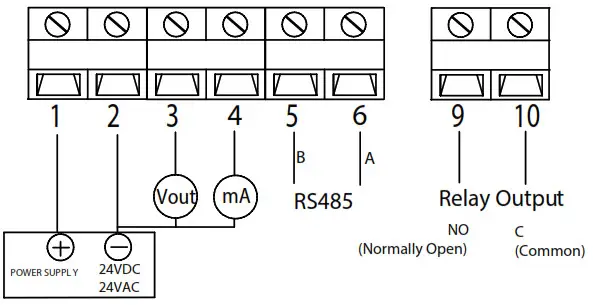
Note: Different models have different electrical terminals. Terminal 3 is 0-10VDC output Terminal 4 is 4-20mA output.
MODE SELECTION
There are two working modes, automatic mode (AUTO) and continuous mode (NORMAL). AUTO mode will automatically reduce the measuring time to extend the service life of the sensor when the dust concentration changes very slightly. Use the MODE jumper to choose the mode. The factory default mode is AUTO.
FIGURE 5: MODE SELECTION

1. Button definition
Users can adjust the parameters.
The backlight of LCD will be off after 30s without any key’s operation.
Note: the LCD will display”—-“when the settings are successful, and display “Err” when failed.
2. Operation instruction
Users can adjust transmitter parameters. Push ![]() button to enter programming.”P000″ will be displayed. Push
button to enter programming.”P000″ will be displayed. Push ![]() button to select the Column and push
button to select the Column and push ![]() button to cycle 0-9 settings. Select different Codes to enter corresponding parameter group settings.
button to cycle 0-9 settings. Select different Codes to enter corresponding parameter group settings.
| Code P999 | Description | Default Value | Parameters |
| Factory Reset | NA | ||
| P401 | Relay Settings(see below for submenu) | Mode:2 SetPoint: 100 Dead Band: 5 On Delay: 3 (5) Off Delay: 1 (5) | (see below for submenu) |
| P483 | RS485 Baud Rate | 9600 | 4800,9600 |
| P484 | RS485 Parity | 0(None) | 0(None), l(Odd), 2(Even) |
| P485 | RS485 Address | 1 | 1-255 (1-32 recommended) |
Notes:
-P999 Reset: Once entered, rST is displayed. Press button Q. All factory default settings will be restored.
-P161 1 Point Calibration: The current value is displayed. Press button > to increase an offset. Press button 0 to decrease an offset. The single point offset is shown. After 2 seconds, the new reading(Current Value + Offset) is shown. Press button 0 to accept changes.
-P401 Relay Settings: Once entered, the current Mode is shown. Followed by Parameter #1, Par. #2, Par. #3, Par. #4
Relays parameters and descriptions:
| Mode 0 | Mode Description Disable Relay | PARA. #1 N/A | PARA. #2 N/A | PARA. #3 N/A | PARA. #4 N/A | Definition |
| 1 | Activate Relay Below SetPoint | SetPoint | Dead Band | Actuate Delay(S) | Restore Delay(S) | 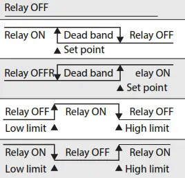 |
| 2 | Activate Relay Above SetPoint | SetPoint | Dead Band | Actuate Delay(S) | Restore Delay(S) | |
| 3 | Activate Relay Between High and Low Limits | Low Limit | High Limit | Actuate Delay(S) | Restore Delay(S) | |
| 4 | Activate Relay Outside High and Low Limits | Low Limit | High Limit | Actuate Delay(S) | Restore Relay(S) |
3. System Error signal
| ERROR CODE | POSSIBLE PROBLEMS | SOLUTION |
| Err | Key input error | Input correct code |
| Er4 | The sensor’s reading is abnormal | Check if the sensor is in good connection with the PCB |
DEVICE CONFIGURATION THROUGH MODBUS RTU
MODBUS RTU INTERFACE
The Modbus Remote Terminal Unit (RTU) data link protocol uses EIA-485 as a two-wire, daisy chain network. A branch is a discrete chain of devices connected to a controller. The max number of devices per segment is (32), as per the Modbus specifications. 4000 ft (1219.2 m) is the maximum recommended length for a segment, which includes all devices from the controller to the last device in the daisy chain.
Each branch must have all devices connected with (A) connected to (A) and (B) connected to (B). If a shielded cable is used, this is not to be connected to the devices. The shielded cable should only be connected on one end to earth ground, usually at the controller.
Each device must be configured for the correct baud rate and have a unique address in each branch. The baud rate for the branch is set by the controller.
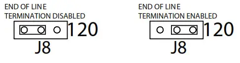
EOL TERMINATION RESISTANCE SELECTION
RS-485 requires that the last device in a chain have a termination resistor. This is controlled using a jumper in the center and right pins(120 0) position marked on FIGURE 7. When the jumper is set to 120 0, a 120 f2 resistance is added in parallel to the data line. When the jumper is set to left and center pins(disabled), the resistance is not added. By default, the jumper is placed in the disabled position.
FIGURE 6: EOL TERMINATION
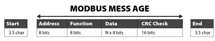
A typical Modbus RTU mode message frame is shown below. In the Modbus RTU mode, the messages between frames are separated by at least 3.5 characters’ time’s silent intervals. If the silent interval between two characters is more than 3.5 characters time, the former character was transferred successfully, and the current character’s transmission starts.
ADDRESS SELECTION
Modbus can locate up to 256 different addresses, including valid addresses from 1-247. Address 0 is for broadcast and addresses 248-255 are reserved for special addresses.
Slave address can be set with compatible Modbus RTU software or via Menu selection(see above for Menu Adjustments). The default address is 1.
BAUD RATE, DATA BITS, PARITY, AND STOP BITS SELECTION
Baud rate is set to 9600, but can also be configured to 4800 via the register or via Menu selection(see above for Menu Adjustments).
The device that requests information is called the Modbus Master and the devices giving the information are Modbus Slaves. The Modbus sensors are slave devices and the number of Data Bits needs to be the same as in the Master device configuration. ACT’s Modbus RTU sensors utilize 8 data bits during communication exchange.
The parity default setting is NONE. Stop bit default setting is 1. Both settings can be adjusted via the register or via Menu selection(see above for Menu Adjustments).
FUNCTION
The function code is the second data in the frame. Valid function codes are from 0-127 (01 H-7FH). See the relevant Modbus standard. It supports 03H/06H function codes, shown as the following Modbus Poll software. The detail register addresses are in: 6 General registers table.
BROADCAST MODE TO WRITE DATA TO SLAVE
Using broadcast mode, customers can write data to all slaves connected to the network. The address of broadcast mode to write data is O.
For example: change slave address with broadcast mode, customer can set a new slave address. Note: since this operation will modify all the addresses of the slavers to the same address, it is NOT applicable for a network of more than one slave.
SPECIAL MODE TO READ DATA FROM SLAVE
With the special mode, customers can read the register data under the circumstance of NOT knowing the slave address.
Address of special mode read data: 255(off)
Note: this operation is applicable for ONLY ONE slave in the network.
MODBUS RTU
| Register Address | R/W R | Type Signed | Definition | Remarks |
| 40001, 00000 | Product code | PM series Product code: 9070 | ||
| 40002, 00001 | R | Signed | PM2.5 Value | PM2.5 = Value , ug/m3 |
| 40003, 00002 | R | Signed | PM10 Value | PM10 = Value , ug/m3 |
| 40014, 00013 | R/W | Signed | RS485-Modbus RTU slave address | Default slave address =1, (RTU,9600,n,8,1) |
| 40016, 00015 | R/W | Signed | Function register | Write 40016=21845 to reset to the factory default setting |
| 40017, 00016 | RAN | Signed | Relay Control Mode | 0: Off 1:Relay activated Below the set point. 2:Relay activated Higher than set point. 3:Relay activated in the set range 4:Relay activated outside the set range |
| 40018, 00017 | R/W | Signed | Back up | |
| 40019, 00018 | R/W | Signed | Setpoint (mode 1 or 2) low limit (mode 3 or 4) regional | Relay control parameters set |
| 40020, 00019 | R/W | Signed | Dead band (mode 1 or 2) high limit(mode 3 or 4) | |
| 40021, 00020 | R/W | Signed | Start delay | |
| 40022, 00021 | Signed | Stop delay | ||
| R/W | ||||
| 40029, 00028 | R/W | Signed | Baud rate | Baud rate: 9600(default) or 4800 |
| 40030, 00029 | R/W | Signed | Parity | Parity : 0: NONE, 1: ODD, 2: EVEN |
Note:
- 40001 is PLC mode ADDRESS (BASE 1); 00000 is PROTOCOL ADDRESS (BASE 0).
- Function register 40016: Use the 06 function code to write the password (21845) to the register 40016 to return to the factory settings.
PRODUCT SPECIFICATIONS
| Supply Voltage: | 16-28VAC/16-35VDC (Reverse Polarity Protection) |
| Output Load Resistance: | 4-20 mA: 500 Ohms maximum 1 0-10 VDC: 2K Ohms minimum |
| Detection Particle Size: | PM2.5: 0.3 — 2.5 pm I PM10: 0.3 — 10 pm |
| Sensing Range: | PM2.5: 0 — 500 pq/m3IPM10: 0 — 600 Rim’ |
| Output: | 4-20mA (Default), 0-10VDC |
| Relay: | N.O. rated 3A @ 30VDC, 3A @ 250VAC |
| Relay flip Point: | 100 ug/m3 |
| Accuracy: | +/-10 pg/m3@ 0 —100 Ng/m’, +/- 10% reading @ 100 –500/600 Ng/m’ @ 25°U50%RH |
| Resolution: | 1 ug/m3 |
| Response Time: | In continuous servie mode, sample time <1s, response time <10s |
| Warm-Up Time: | 15 minutes |
| Service Life: | MTBF more than 3 years in continuous service mode, service life up to 8-10 years in auto (intermittent) service mode |
| Communication Protocol: | Modbus RTU; EIA RS-485 |
| Sensor Addresses: | 1-247 |
| Support Baud Rates: | 4800 or 9600 |
| Parity: | None/Even/Odd |
| Stop Bits: | 1 |
| Data Bits: | 8 |
| Connections/Wire Size: | Screw Terminal Blocks / 16 AWG (1.31 me) to 22 AWG (0.33 mm2) |
| Terminal Block Torque Rating: | 0.45 lbs-in (0.5 Nm) nominal |
| Operating Temperature Range: | 32 to 122°F (0 to 50°C) |
| Storage Temperature Range: | -30 to 70°F (-34 to 21°C) |
| Operating Humidity Range: | 10 to 95% RH, non-condensing |
| Enclosure Protection: | IP30 |
| Enclosure Material / UL Flammability: | ABS Plastic / UL94V-0 |
WARRANTY
The ACI PM Room Series are covered by ACI’s Two (2) Year Limited Warranty, which is located in the front of ACI’S SENSORS & TRANSMITTERS CATALOG or can be found on ACI’s website: www.workaci.com.
W.E.E.E. DIRECTIVE
At the end of their useful life the packaging and product should be disposed of via a suitable recycling center. Do not dispose of household waste. Do not burn.
Notes
![]()
![]()
Automation Components, Inc.
2305 Pleasant View Road | Middleton, WI 53562
Phone: 1-888-967-5224 | Website: workaci.com
Version: 3.0
I0000941


 Desktop Display User Manual")
