CZONE RV1 Enerdrive Independent Power Solutions
Copyright
This document is copyright 2018 under the Creative Commons agreement. Rights are granted to research and reproduce elements of this document for non-commercial purposes on the condition that BEP is credited as the source. Electronic re-distribution of the document in any format is restricted, to maintain quality and version control.
Important
BEP strives to ensure all information is correct at the time of printing. However, the company reserves the right to change without notice any features and specifications of either its products or associated documentation.
Translations: In the event that there is a difference between a translation of this manual and the English version, the English version should be considered the official version.
It is the owner’s sole responsibility to install and operate the device in a manner that will not cause accidents, personal injury or property damage.
Use of This Manual
Copyright © 2018 BEP Marine LTD. All rights reserved.
Reproduction, transfer, distribution or storage of part or all of the contents in this document in any form without the prior written permission of BEP Marine is prohibited.
This manual serves as a guideline for the safe and effective operation, maintenance and possible correction of minor malfunctions of the RV1.
GENERAL INFORMATION
USE OF THIS MANUAL
Copyright © 2016 BEP Marine. All rights reserved.
Reproduction, transfer, distribution or storage of part or all of the contents in this document in any form without the prior written permission of BEP Marine is prohibited.
This manual serves as a guideline for the safe and effective operation, maintenance and possible correction of minor malfunctions of the RV1 CZone Module.
This manual is valid for the following models:
| Description | Part number |
| RV1 MID SPEC | 80-911-0221-00 |
It is obligatory that every person who works on or with the RV1 is completely familiar with the contents of this manual, and that he/she carefully follows the instructions contained herein
Installation of, and work on the RV1, may be carried out only by qualified, authorized and trained personnel, consistent with the locally applicable standards and taking into consideration the safety guidelines and measures (chapter 2 of this manual). Please keep this manual in a secure place!
GUARANTEE SPECIFICATIONS
BEP Marine guarantees that this unit has been built according to the legally applicable standards and specifications. Should work take place which is not in accordance with the guidelines, instructions and specifications contained in this Installation manual, then damage may occur and/or the unit may not fulfil its specifications. All of these matters may mean that the guarantee becomes invalid.
QUALITY
During their production and prior to their delivery, all of our units are extensively tested and inspected. The standard guarantee period is two years.
VALIDITY OF THIS MANUAL
All of the specifications, provisions and instructions contained in this manual apply solely to standard versions of the Combined Output Interface delivered by BEP Marine.
LIABILITY
BEP can accept no liability for:
Consequential damage due to use of the RV1. Possible errors in the manuals and the results thereof
CAREFUL! Never remove the identification label
Important technical information required for service and maintenance can be derived from the type number plate.
CHANGES TO THE RV1 MODULE
Changes to the RV1 may be carried out only after obtaining the written permission of BEP.
SAFETY AND INSTALLATION PRECAUTIONS
WARNINGS
Safety instructions and warnings are marked in this manual by the following pictograms:
CAUTION
Special data, restrictions, and rules with regard to preventing damage.
WARNING
A WARNING refers to possible injury to the user or significant material damage to the RV1 if the user does not (carefully) follow the procedures.
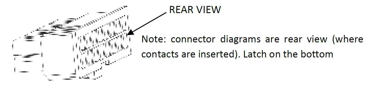
NOTE
A procedure, circumstance, etc, which deserves extra attention.
USE FOR INTENDED PURPOSE
- The RV1 is constructed as per the applicable safety-technical guidelines.
- Use the RV1 only:
• In technically correct conditions
• In a closed space, protected against rain, moisture, dust and condensation
• Observing the instructions in the installation manual
WARNING Never use the RV1 in locations where there is danger of gas or dust explosion or potentially flammable products! - Use of the RV1 other than mentioned in point 2 is not considered to be consistent with the intended purpose.
BEP Marine is not liable for any damage resulting from the above.
ORGANIZATIONAL MEASURES
The user must always:
Have access to the user’s manual and be familiar with the contents of this manual
MAINTENANCE AND REPAIR
- Switch off supply to the system
- Be sure that third parties cannot reverse the measures taken
- If maintenance and repairs are required, only use original spare parts
GENERAL SAFETY AND INSTALLATION PRECAUTIONS
- Connection and protection must be done in accordance with local standards
- Do not work on the RV1 or system if it is still connected to a power source. Only allow changes in your electrical system to be carried out by qualified electricians
- Check the wiring at least once a year. Defects such as loose connections, burned cables, etc. must be corrected immediately
OVERVIEW
DESCRIPTION
RV1 is CZone’s first dedicated digital switching and integration module for recreational & specialty vehicles. RV1 features an impressive 76 input and output channels including 8 reversing motor channels for direct control of slide outs, awnings, shades, and levelling systems. RV1 also includes the latest smart switching technology, built-in battery monitoring and multiple network interfaces for seamless 3rd party system integration. By consolidating the functionality of multiple CZone modules into one compact unit, RV1 reduces system cost, complexity and installation time. RV1 enables RV builders to meet customer expectations for smart, automated and connected systems at an affordable price point.
FEATURES
- 76 channels in a robust, compact enclosure ensures a single module digital switching solution across a wide range of RV’s & SV’s
- Smart MOSFET switching technology provides superior reliability, silent operation and current monitoring on all output channels
- 8 Reversing Motor (H-Bridge) channels for direct control of slide outs, awnings, shades and levelling systems
- Internal Battery State of Charge Monitoring, no additional modules or shunts required and low power draw on sleep mode (<5mA)
- 32 Signal Inputs for 0-32V, 0-1000Ω sensors & switches. Monitor Batteries, Tank Levels, LPG, Temperature and Pressure Levels
- Cost effective Molex/TE automotive connectors with multiple cable routing options to suit various install locations and space availability
- Auto Generator Start and load shedding functions can be configured to maximize battery runtime and life
- Automatic Climate Control feature allows direct control of HVAC & Heating systems with intuitive Climate Controls on CZone Displays
IN THE BOX
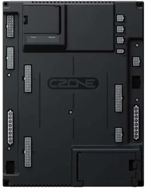
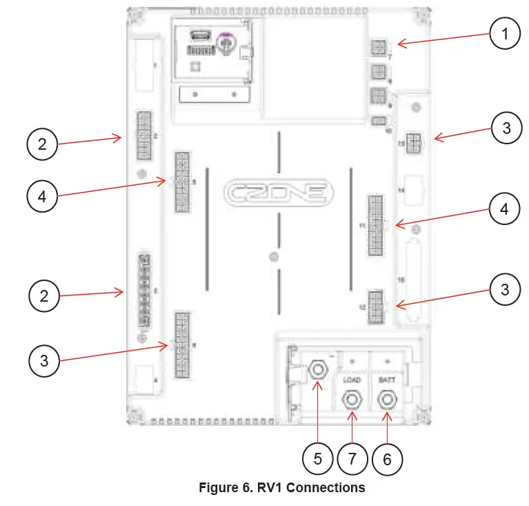
RV1 OVERVIEW
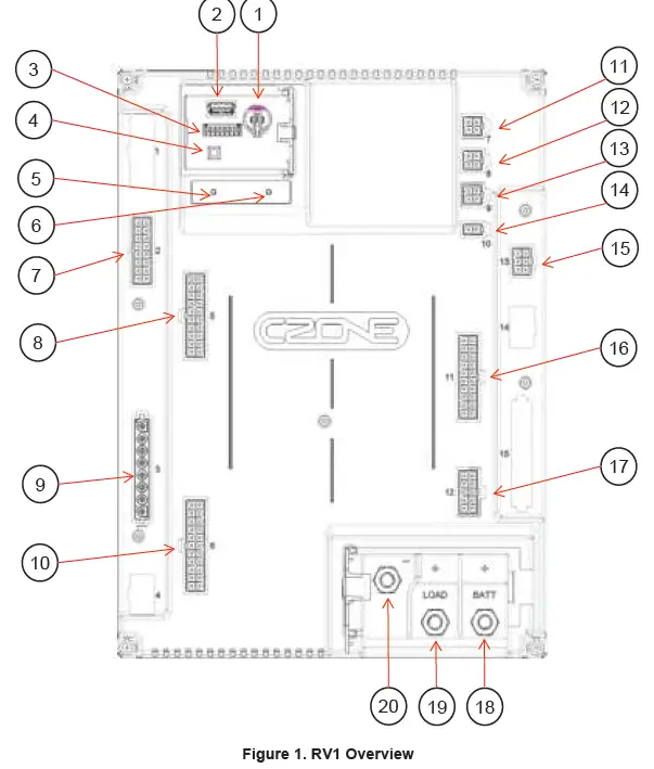
| Component | Component | ||
| 1. | Real Time Clock Battery Holder | 11. | Connector 7, CZone NMEA2000 |
| 2. | USB Interface | 12. | Connector 8, RV-C |
| 3. | Dipswitch | 13. | Connector 9, Slave CAN BUS |
| 4. | USB Function Button | 14. | Connector 10, LIN BUS |
| 5. | Power Indicator LED | 15. | Connector 13, Hight Current Outputs |
| 6. | Network Status LED | 16. | Connector 11, Switch/Signal Inputs |
| 7. | Connector 2, Low Current H-Bridges | 17. | Connector 12, Low Current Outputs |
| 8. | Connector 5, Switch/Signal Inputs | 18. | Battery Positive Main Stud |
| 9. | Connector 3, High Current H-Bridges | 19. | Load Positive Stud |
| 10. | Connector 6, Mid Current Outputs | 20. | Battery Negative Stud |
LED INDICATORS
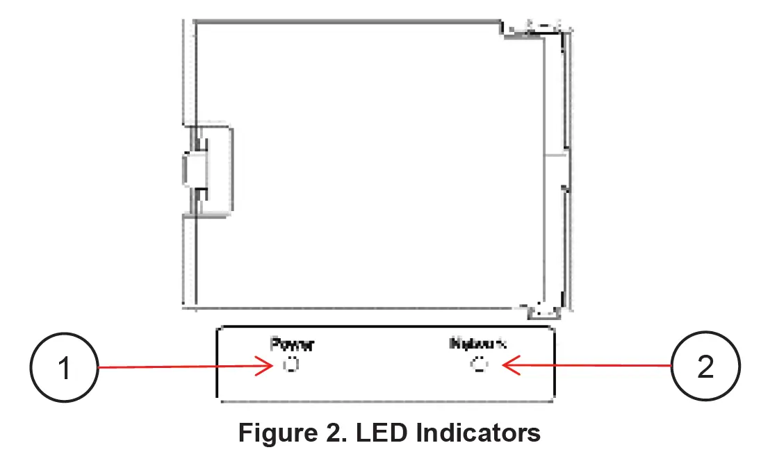
1. Power LED
| Colour | Description |
| Extinguished | Power Disconnected |
| Green | Power Available (>12V for 12V System, >20V for 24V System) |
| Red | Low Volts (<12V for 12V System, <20V for 24V System) |
| Red Flash | USB Operation Ongoing |
2. Network Status LED
| Colour | Description |
| Extinguished | Network Power Disconnected |
| Green | Network Power Connected |
| Red Flash | Network traffic |
USB PORT
The USB port on the RV1 allows system software updates and configuration files to be loaded from a USB Memory Stick. The Power LED is used on the RV1 as the USB status indicator.
General Requirements & Tips
- Make sure the USB drive is FAT32 formatted.
- USB drive sizes up to 32GB are recommended.
- Most USB brands have been verified up to 32GB in size, including Strontium, Sandisk, Toshiba, Verbatim, Kingston, Samsung, Apacer etc.
- For USB drives 64GB and above only a limited number of devices from Kingston have been verified for operation.
- It is best, but not necessary, to use an empty USB drive for these operations.
Reading Configuration From Network
To read the existing configuration from the network to the USB drive you must:
- Insert a USB drive into the RV1 with NO existing (*.zcf or *.czfwp) files in the root folder.
- Press the USB button for 5sec or until the Power LED flashes RED.
- Wait for the Power LED to turn solid green before removing it. This should take less than 20sec. Once done, it will create/update 4 files:
- *.zcf – The configuration file read from the network
- *.csv – A spreadsheet listing information about the system and modules connected to the network
- CZone.bak – A backup copy of the configuration file. This needs to be present when writing updated configuration back to the network
- CZone USB Result.txt – A text file describing the result of the last operation performed, as well as these instructions
Writing Configuration To Network
To write the system configuration from the USB to the network you must:
- Insert a USB drive into the RV1. The following files must present in the root folder:
- CZone.bak – This config file backup must match the existing system config before a config update can occur. This file is generated by copying the existing configuration to the USB as above.
- *.zcf – A single configuration file to be written to the network. If more than one file is present no update will occur.
- No firmware update files (*.czfwp).
- Press the USB button for 5sec or until the Power LED flashes RED.
- After several seconds, the Power LED will flash Green.
- Wait for the Power LED to turn solid green before removing it. This should take less than 20sec.
- Once the system configuration has been updated the following files will be created/updated:
- *.csv – A basic spreadsheet listing information about the system and modules connected to the network.
- CZone USB Result.txt – A text file describing the result of the last operation performed, as well as these instructions.
Updating Device Firmware
To update firmware of devices on the network you must:
- Insert a USB drive with the following files in the root folder: The following files must be present in the root folder:
- *.czfwp – A single CZone firmware update file to be used to update devices in the system.
- No configuration files (*.zcf).
- Press the USB button for 5sec or until the Power LED flashes RED.
- Wait for the Power LED to turn solid green before removing it, this operation can take 10-40minutes depending on the number of different module types in the system.
- Once the firmware has been updated the following files will be created/updated:
- *.csv – A basic spreadsheet listing information about the system and modules connected to the network.
- CZone USB Result.txt – A text file describing the result of the last operation performed, as well as these instructions.
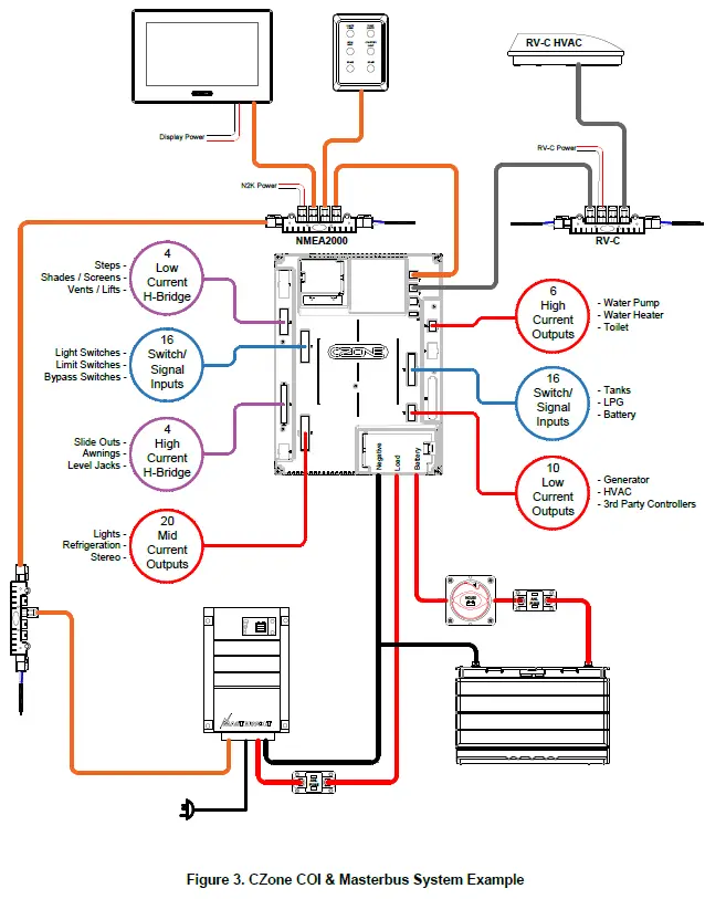
SYSTEM EXAMPLE
INSTALLATION
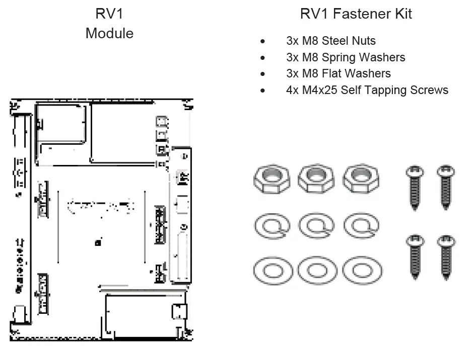
THINGS YOU NEED
- RV1 Module
- Connector Kit (part # 80-911-0225-00)
- TE Pro-Crimper lll (part # 1976444-1) or similar for crimping 6mm (10AWG) wire (optional)
- Appropriate network cables (RV-C cabling part numbers available in Ordering Information)
- Screwdriver and drill bits
- Electrical Tools

ENVIRONMENT
Obey the following stipulations during installation:
- Ensure the RV1 is located in a cool, dry location.
- Ensure the RV1 is located in an easily accessible location for firmware and configuration updates.
- Ensure indicator LED’s are visible for troubleshooting.
- The RV1 must be mounted at least 50mm away from high current carrying conductors.
- Ensure RV1 is mounted either vertically or horizontally.
- Ensure the bulkhead that the unit will be attached to is sufficiently strong to take the weight of the unit.
24V SURGE PROTECTION REQUIREMENTS
To protect against a load dump and inductive voltage spikes caused by some loads in a 24v installation, a BEP Surge Protection module is required to be installed in the power supply to the Modules.
- Only required in 24v installations. 24v Surge Protection Module part # – 80-707-0005-00.
- One Surge Protection Module per cluster of RV1 modules, within reasonable proximity:
- A cluster is one or more RV1 modules installed within a 2m proximity of each other, supplied by a common supply circuit.
- Reasonable proximity can be defined as modules installed within 2m of each other.
- Larger installations may require more than one Surge Protection Module:
- If another module or module cluster exists on its own power supply branch circuit.
- If another module cluster exists on the same supply branch but is more than 2m from the surge module.
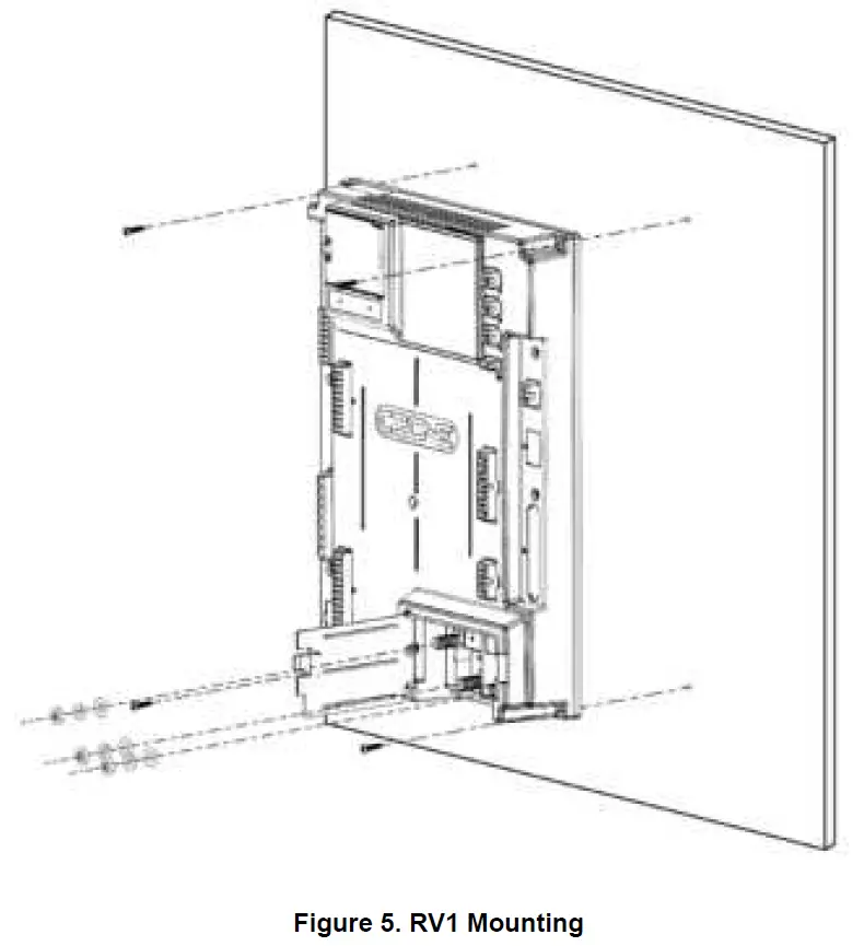
MOUNTING
When mounting the RV1, a few guidelines must be kept in mind. A feature of the RV1 is a built-in accelerometer for future level monitoring capabilities, so mounting location must be thoroughly thought out.
- The RV1 can be mounted on any solid surface within the RV.
- The RV1 must not be mounted on a movable panel, i.e., a draw or a cupboard door.
- Screw the RV1 to the surface with 4 x 8G or 10G (4mm or 5mm) self-tapping screws or bolts, ensuring mounting location is structural enough to support the RV1 and cabling when connected.
- Leave a minimum space of 50mm around the RV1 to allow sufficient space for airflow.
PLANNING
- Make a list of all inputs and outputs to be wired to the RV1 and take note of the channel ratings and functions as shown in the tables below.
- When planning DC battery cabling, be sure to follow specifications for correct wiring of battery, 24hr loads, and charging systems.
- Ensure loads are wired to the appropriate channel for the functionality required.
- Ensure switches and signal inputs are correctly installed and wired correctly.
- For DC Output loads with a continuous current exceeding max channel current, it is possible to parallel output channels, refer to tables below on parallel channel compatibility (do not parallel outputs between connectors).
- Paralleling is not available on H-Bridge channels.
- H-Bridge channels may be used as DC Outputs however both positive and negative supplying the load must originate from H-Bridge channel connector. Take note that channel ratings may change if being configured as a DC output.
Connector 2 – 4x H-Bridge 5A

| Pin No. | Function | Notes |
| 1 | H-Bridge 5A 5- |
Channel Features · Current monitoring, software fusing and PWM all channels
Channel Limitations · Max 5A continuous per H- Bridge channel · Max 17A motor in-rush · No parallel · 5A continuous channel rating if configured as a DC output channel. |
| 2 | H-Bridge 5A 6- | |
| 3 | No Connect | |
| 4 | No Connect | |
| 5 | H-Bridge 5A 7- | |
| 6 | H-Bridge 5A 8- | |
| 7 | No Connect | |
| 8 | No Connect | |
| 9 | H-Bridge 5A 5+ | |
| 10 | H-Bridge 5A 6+ | |
| 11 | No Connect | |
| 12 | No Connect | |
| 13 | H-Bridge 5A 7+ | |
| 14 | H-Bridge 5A 8+ | |
| 15 | No Connect | |
| 16 | No Connect |
Connector 3 – 4x H-Bridge 35A

| Pin No. | Function | Notes |
| 1 | H-Bridge 35A 1- | Channel Features · Current monitoring, software fusing and PWM all channels Channel Limitations · Max 35A per channel (30 sec) · Max 25A per channel (7 min) · Max 70A motor in-rush · No parallel · 15A continuous channel rating if configured as a DC output channel. |
| 2 | H-Bridge 35A 1+ | |
| 3 | H-Bridge 35A 2- | |
| 4 | H-Bridge 35A 2+ | |
| 5 | H-Bridge 35A 3- | |
| 6 | H-Bridge 35A 3+ | |
| 7 | H-Bridge 35A 4- | |
| 8 | H-Bridge 35A 4+ |
Connector 5 / Connector 11 – 8x Switch Inputs, 8x Signal Inputs

| Pin No. | Function | Notes |
| 1 | Switch Input 1 / Wake | Switch Input Features ·Switch to Pos or Neg · Switch Input 1 can also be used to wake RV1 from sleep mode |
| 2 | Switch Input 2 | |
| 3 | Switch Input 3 | |
| 4 | Switch Input 4 | |
| 5 | Battery Neg (Optional) | |
| 6 | Switch Input 5 | |
| 7 | Switch Input 6 | |
| 8 | Switch Input 7 | |
| 9 | Switch Input 8 | |
| 10 | Battery Neg (Optional) | |
| 11 | Signal Input 1 | Signal Input Features · 0-32V, 0-1kΩ (Display as Battery Volts, Fluid Level, Temperature, Pressure) · Temp Sensors pre-calibrated (PT100, Dometic 3106486.0) · Switch to Pos or Neg, Multiplex |
| 12 | Signal Input 2 | |
| 13 | Signal Input 3 | |
| 14 | Signal Input 4 | |
| 15 | Battery Neg (Optional) | |
| 16 | Signal Input 5 | |
| 17 | Signal Input 6 | |
| 18 | Signal Input 7 | |
| 19 | Signal Input 8 | |
| 20 | Battery Neg (Optional) |
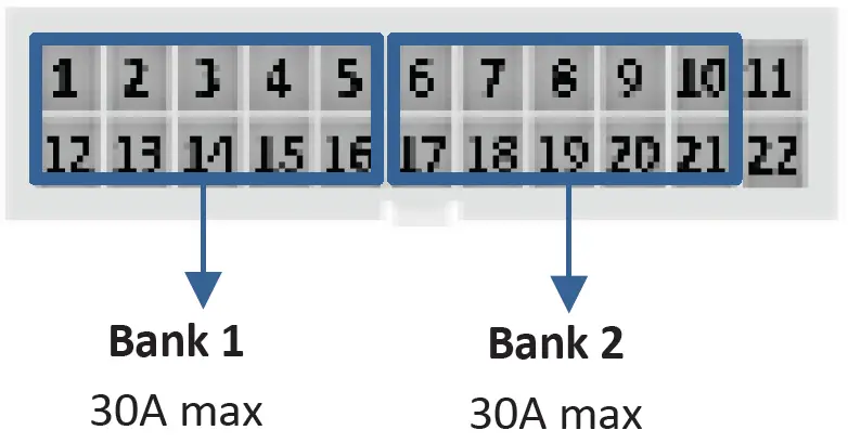
Connector 6 – 20x DC Outputs 5A

| Pin No. | Function | Notes |
| 1 | DC Output 5A 1 | Channel Features · Current monitoring, software fusing and PWM all channels · Parallel up to 20 outputs Channel Limitations · 5A Max per channel · 3A Max per channel for Halogen bulbs (no dimming) · 1.5A Max per channel for Halogen bulbs (with dimming) · 30A Max total per Bank
|
| 2 | DC Output 5A 2 | |
| 3 | DC Output 5A 3 | |
| 4 | DC Output 5A 4 | |
| 5 | DC Output 5A 5 | |
| 6 | DC Output 5A 6 | |
| 7 | DC Output 5A 7 | |
| 8 | DC Output 5A 8 | |
| 9 | DC Output 5A 9 | |
| 10 | DC Output 5A 10 | |
| 11 | No Connect | |
| 12 | DC Output 5A 11 | |
| 13 | DC Output 5A 12 | |
| 14 | DC Output 5A 13 | |
| 15 | DC Output 5A 14 | |
| 16 | DC Output 5A 15 | |
| 17 | DC Output 5A 16 | |
| 18 | DC Output 5A 17 | |
| 19 | DC Output 5A 18 | |
| 20 | DC Output 5A 19 | |
| 21 | DC Output 5A 20 | |
| 22 | No Connect |
Connector 12 – 10x DC Output 0.5A

| Pin No. | Function | Notes |
| 1 | DC Output 0.5A 1 | Channel Features · Current monitoring & software fusing all channels · Parallel up to 10 outputs |
| 2 | DC Output 0.5A 2 | |
| 3 | DC Output 0.5A 3 | |
| 4 | DC Output 0.5A 4 | |
| 5 | DC Output 0.5A 5 | |
| 6 | DC Output 0.5A 6 | |
| 7 | DC Output 0.5A 7 | |
| 8 | DC Output 0.5A 8 | |
| 9 | DC Output 0.5A 9 | |
| 10 | DC Output 0.5A 10 |
Connector 13 6x DC Outputs 10A

| Pin No. | Function | Notes |
| 1 | DC Output 10A 1 | Channel Features · Current monitoring software fusing and PWM all channels · Parallel up to 6 outputs Channel Limitations · 10A Max per channel · 35A Connector Max |
| 2 | DC Output 10A 2 | |
| 3 | DC Output 10A 3 | |
| 4 | DC Output 10A 4 | |
| 5 | DC Output 10A 5 | |
| 6 | DC Output 10A 6 |
Connector 7 – NMEA2000

| Pin No. | Function |
| 1 | CAN H |
| 2 | CAN L |
| 3 | N2K GND |
| 4 | N2K POWER |
Connector 8 – RV-C
| Pin No. | Function |
| 1 | CAN H |
| 2 | CAN L |
| 3 | No Connect |
| 4 | No Connect |
Connector 9 – Slave CAN
| Pin No. | Function |
| 1 | CAN H |
| 2 | CAN L |
| 3 | No Connect |
| 4 | No Connect |
Connector 10 – LIN

| Pin No. | Function |
| 1 | LIN |
| 2 | GND |
CONNECTIONS
The following order of connections for the RV1 should be followed.
- Connect NMEA2000 network
1. The RV1 Module uses automotive network connectors for the NMEA2000 network. BEP’s RV-C network component range part numbers are available in (6.2 Ordering Information).
2. Connect NMEA2000 drop cable from the RV1 to NMEA2000 backbone.
3. Ensure the NMEA2000 network is properly terminated and connected to a 12V power source (Do not power up network yet). - H-Bridge Channels
1. Referring to the loads list, select H-Bridge channels for required current rating.
2. Strip and crimp the H-Bridge loads with the appropriate contact and crimp tool.
3. Insert contacts into associated H-Bridge plug.
4. Insert the connector into the RV1, ensuring connector is correctly seated. - DC Output Channels
1. Referring to the loads list, select DC Output channels for required current rating.
2. Strip and crimp the DC Output loads with the appropriate contact and crimp tool.
3. Insert contacts into associated DC Output plug.
4. Insert the connector into the RV1, ensuring connector is correctly seated. - Switch / Signal Input Channels
1. Referring to the tables above, select a channel for the required function. Signal Inputs may be re-purposed as Switch Inputs when configuring.
2. Take note of connector pinout for Switch and Signal Inputs and assign a pin.
3. Strip and crimp the Switch/ Signal Inputs with the appropriate contact and crimp tool.
4. Insert contacts into associated plug.
5. Insert the connector into the RV1, ensuring connector is correctly seated. - Connect DC Negative
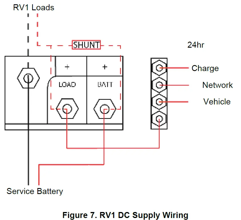
1. Connect an appropriately sized cable from the battery negative terminal or main negative bus to the RV1’s M8 negative stud. The Negative cable must be capable of carrying combined current of all H-Bridge channels.
2. Maximum recommended cable size is 70mm² (2/0). Cables larger than 70mm² (2/0) should be connected to a positive stud first with a link to the RV1. - Connect DC Positive
1. Connect an appropriately sized and fused cable from the battery positive terminal to the RV1’s ‘Batt’ positive stud. The positive cable must be of sufficient size to carry the maximum current of all loads connected to the RV1, as well as the 24hr loads connected to the ‘Load’ stud, and have a fuse/circuit breaker rated to protect the cable, volt drop should be kept to a minimum.
2. Maximum total load for the RV1 including 24hr loads connected via ‘Load’ stud is 150A.
3. Maximum recommended cable size is 70mm² (2/0). Cables larger than 70mm² (2/0) should be connected to a positive stud first with a link to the RV1. - Connect 24hr Loads (Optional)
1. If built-in State of Charge monitoring is to be used, then connect 24hr loads to the RV1’s ‘Load’ Stud. Take extra care when wiring the 24hr loads to ensure that no 24hr load is connected directly to the battery. Failure to connect 24hr loads through RV1 will result in inaccuracies with battery monitoring calculated within the RV1.
2. All ‘Loads’ must be fused correctly for devices.
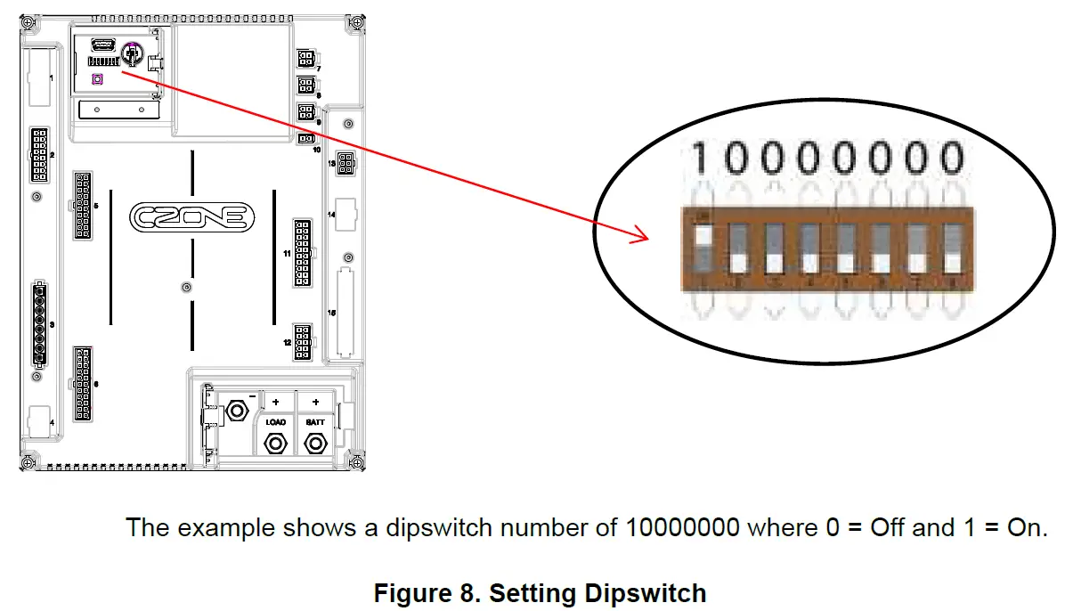
SET DIPSWITCH
Using a small screwdriver carefully set the dipswitch on the RV1. The dipswitch number must be unique for all modules on the CZone network and must match the dipswitch setting in the configuration to function correctly.
INITIAL POWER UP
- Check all plugs are securely seated and connections are tight.
- Power up the NMEA2000 network.
- Check that the NMEA2000 Network LED lights up. It may also be flashing if other devices are present and transmitting data.
- Turn the switch/circuit breaker on supplying the RV1’s main positive stud.
- Check that the Power indicator LED is green.
- Check the software version on the RV1 with the CZone Configuration Tool and update if necessary.
- Write configuration file to the RV1 and the rest of the CZone modules on the system (Refer to the CZone Configuration Tool Instructions for details on how to configure the RV1).
- Test all inputs and outputs for configured functionality.
SOFTWARE FUSING
The use of Smart MOSFETs in the RV1 means no need for physical fuses. Whilst configuring loads its important that correct fuse values are entered to ensure correct circuit & cabling protection. Extra care should be taken when assigning fuse values and type to match load device specs.
SPECIFICATIONS
TECHNICAL SPECIFICATIONS
| Specifications | |
| Communication | NMEA2000, RV-C, LIN Bus (Future) |
| Output Channels | 36 (6 x 10A, 20 x 5A, 10 x 0.5A) |
| H-Bridge Channels | 8 (4 x 35A, 4 x 5A) |
| Input Channels | 16 x Switch Inputs (Pos or Neg Switch) 16 x Signal Inputs (0-32v, 0-1000Ω, PT100, Dometic 3106486.0, Pos or Neg Switch, Multiplex) |
| PWM | All 10A, 5A and H-Bridge Outputs (100 – 250Hz Configurable) |
| Additional Monitoring | 1 x Volt, Amps & SOC sense on Main Positive Stud |
| Circuit Protection | Software Overcurrent & Hardware Short Circuit protection |
| Current Monitoring | All Output including low & run current detection |
| Maximum Module Current | 150A |
| Power Supply | 3 x M8 (5/16″) Stud: Battery Positive, Battery Negative & Battery Load/24H (Optional) |
| Power Consumption | 350mA (Operating) 35mA (Idle) <5mA (Sleep) |
| Operating Voltage Range | 9-32V (with Power Available LED) |
| Operating Temperature Range | -15C to +55C (-5F to +131F) |
| Operating Storage Range | -40C to +85C (-40F to +185F) |
| Ingress Protection | IPx0 (RV applications only) |
| Connectors | TE Val-U-Lok/Mate-N-Lok or Molex equivalent |
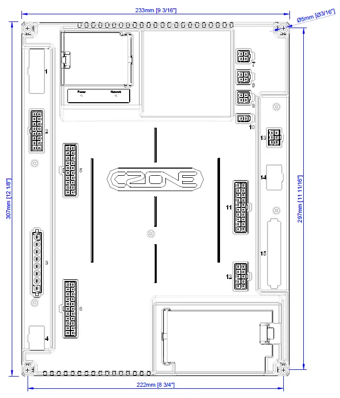
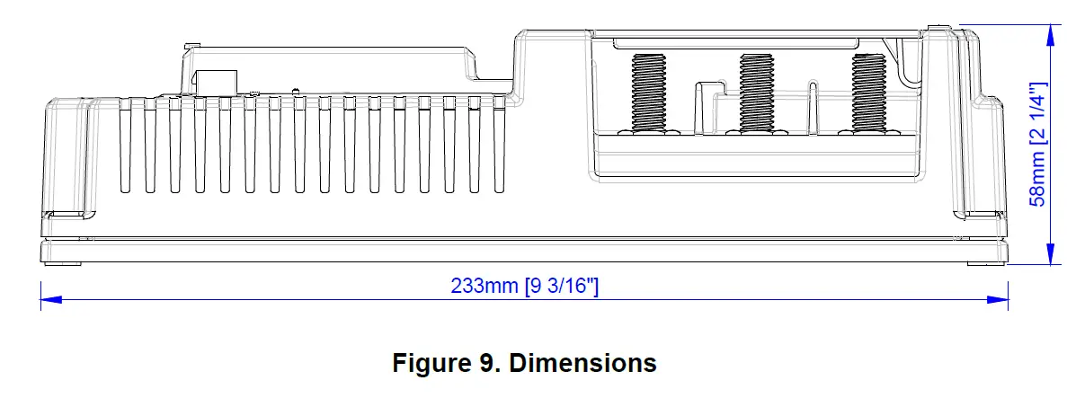
| Dimensions (W x H x D) | 233 x 307 x 58mm (9.17 x 12.09 x 2.28”) |
| Weight | 1.4kg (3lb) |
| Compliance | CE, RCM, UK-CA |
NMEA 2000 PGN’S
NMEA 2000 PGN’s sent from the RV1
| PGN Number | Description | Fields |
| 127508 | Battery Status | Battery Voltage, Battery Current |
| 127506 | DC Detailed Status | State of Charge, Time Remaining, DC Type |
| 127505 | Fluid Level | Fluid Level |
| 130312 | Temperature | Actual Temperature |
| 130314 | Pressure | Pressure |
| 130316 | Temperature, Extended Range | Actual Temperature |
DIMENSIONS
ORDERING INFORMATION
RV1 PART NUMBERS AND ACCESSORIES
| Part Number | Description |
| 80-911-0221-00 | RV1 MID SPEC KIT |
| 80-911-0225-00 | RV1 MID SPEC CONNECTOR KIT |
| MSC-RV-KIT | RV1 FASTENER KIT SPARE |
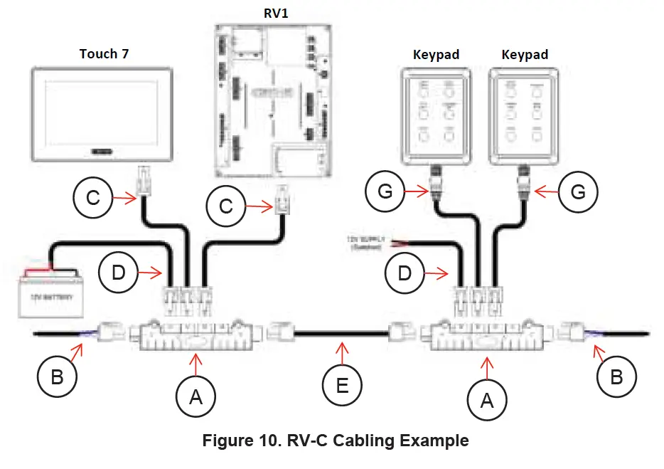
RV-C CABLING PART NUMBERS
| Part Number | Description | |
| A | 80-911-0206-00 | RV-C 4WAY TEE |
| B | 80-911-0207-00 | RV-C TERMINATOR |
| C | 80-911-0241-00 | RVC-RVC BACKBONE/DROP CABLE 0.5M |
| C | 80-911-0242-00 | RVC-RVC BACKBONE/DROP CABLE 1M |
| C | 80-911-0243-00 | RVC-RVC BACKBONE/DROP CABLE 2M |
| C | 80-911-0244-00 | RVC-RVC BACKBONE/DROP CABLE 5M |
| 80-911-0245-00 | RVC-RVC BACKBONE CABLE 8M | |
| D | 80-911-0246-00 | RVC POWER CABLE 1M |
| E | 80-911-0247-00 | RVC POWER ISOLATOR CABLE |
| G | 80-911-0208-00 | N2K DEVICE TO RV-C DROP CABLE 1M |
| G | 80-911-0209-00 | N2K DEVICE TO RV-C DROP CABLE 2M |
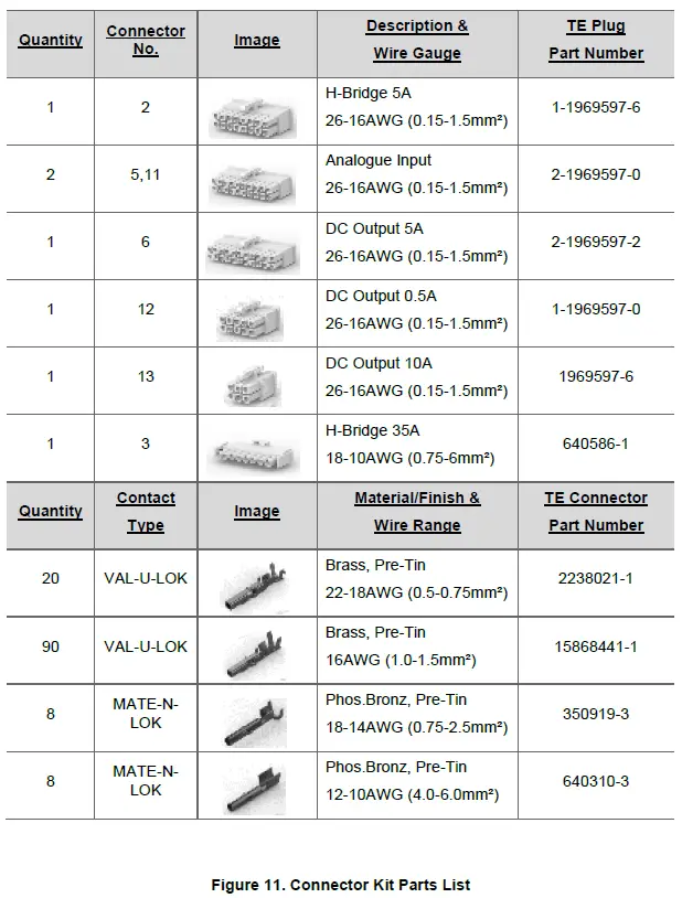
CONNECTOR KIT PARTS LIST