BODYCRAFT 50442 Jones Functional Cable Crossover Option for Jones Commercial Machine Owner’s Manual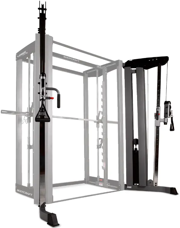
BEFORE YOU BEGIN
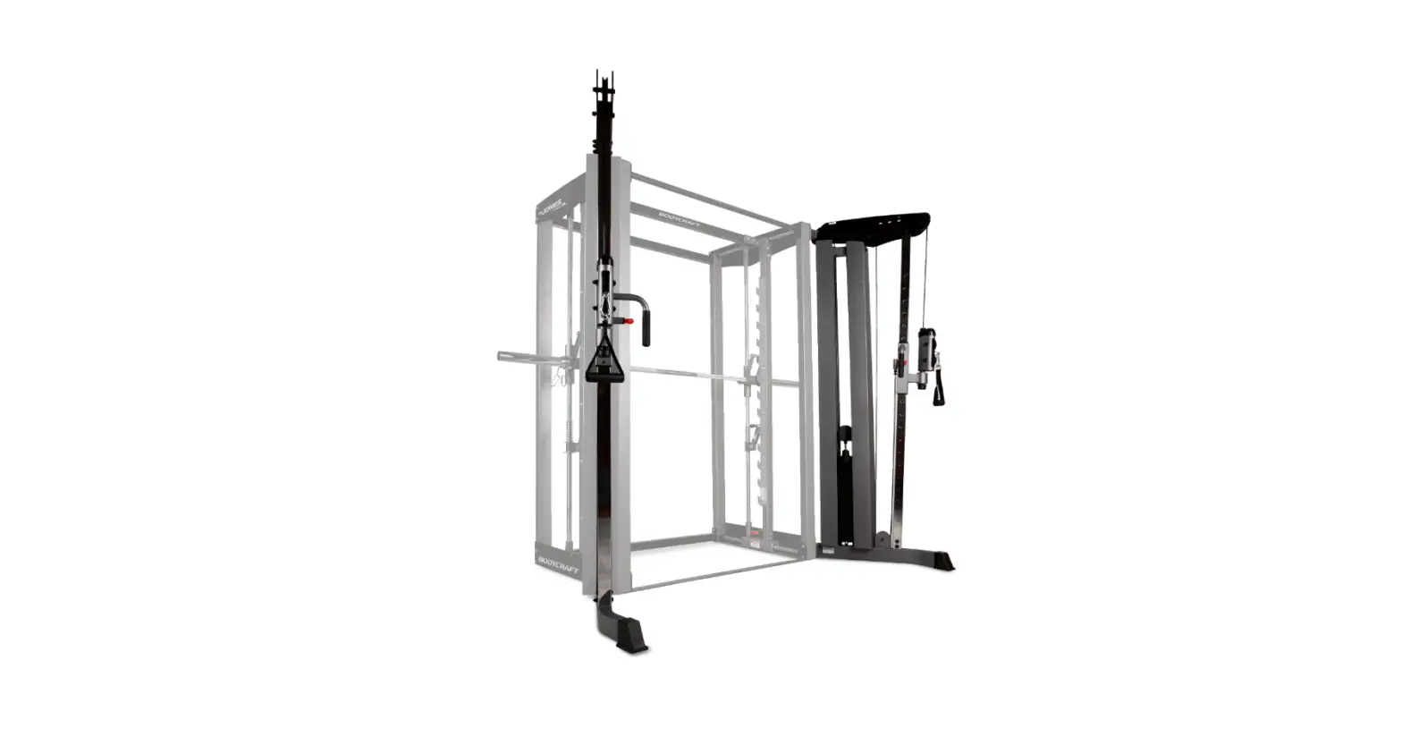
Congratulations and thank you for selecting the JONES MACHINE strength training system. The JONES MACHINE offers an impressive array of strength training exercises to develop every major muscle group of the body. Whether your goal is cardiovascular fitness, a shapely, toned body or dramatic muscle size and strength, the JONES MACHINE will help you achieve the specific results you want.
For your safety and benefit, read this manual and the accompanying literature before using the JONES MACHINE. Keep this manual for future reference. If you have additional questions, please call your local dealer or our customer service department at 800-990-5556 Monday through Friday, 9 a.m. until 5 p.m. Eastern Time.
IMPORTANT SAFETY NOTES
There is a risk assumed by individuals who use this type of equipment. Before beginning this or any other exercise program consult your physician. This is especially important for individuals over the age of 35 or persons with pre-existing health problems. Recreation Supply, Inc. assumes no responsibility for personal injury or property damage sustained by or through use of this product.
- This product must be assembled on a flat, level surface to assure its proper function.
- Clean pads and frame on a regular basis. We recommend warm, soapy water. Do not use harsh or abrasive chemicals.
- Inspect and tighten all parts before every use. Replace any worn parts immediately. Failure to do so may result in serious injury.
- Keep children away from the JONES MACHINE at all times.
- Keep your hands away from cables and pulleys during operation. Keep your hands away from moving parts other than the designated handles.
- When adjusting the seat, make sure the spring pin is fully engaged. If not, the seat may slip and cause serious injury.
- Make certain all cables are seated within the pulleys before every use.
- Exercise with care to avoid injury.
- If unsure about the proper use of the JONES MACHINE strength training system call your local dealer or our customer service department at 800-
OVERVIEW
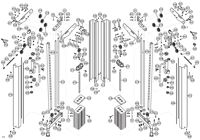
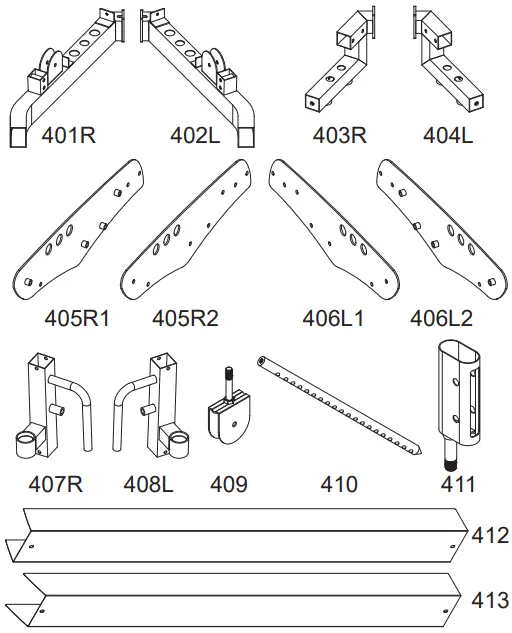
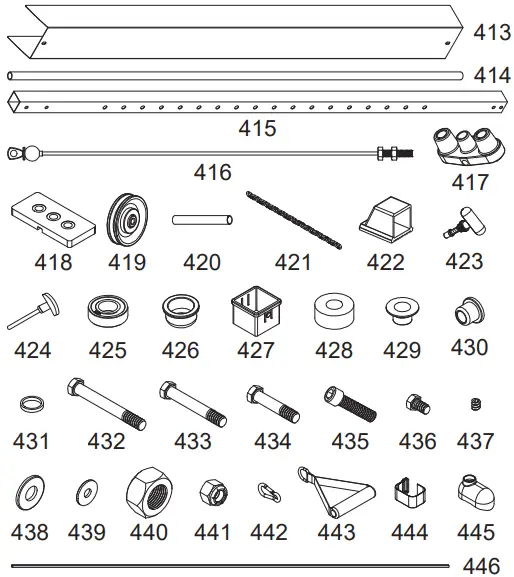
PARTS LIST
| NO | DESCRIPTION | QTY |
| 401R | RIGHT BASE FRAME | 1 |
| 402L | LEFT BASE FRAME | 1 |
| 403R | RIGHT TOP FRAME | 1 |
| 404L | LEFT TOP FRAME | 1 |
| 405R1 | RIGHT FRONT TOP PANEL | 1 |
| 405R2 | RIGHT | 1 |
| 406L1 | LEFT FRONT TOP PANEL | 1 |
| 406L2 | LEFT REAR TOP PANEL | 1 |
| 407R | RIGHT CABLE HEIGHT ADJUSTER | 1 |
| 408L | LEFT CABLE HEIGHT ADJUSTER | 1 |
| 409 | PULLEY BRACKET | 2 |
| 410 | SELECTOR ROD | 2 |
| 411 | SWIVEL PULLEY HOUSING | 2 |
| 412 | FRONT STACK SHROUD | 2 |
| 413 | REAR STACK SHROUD (colse to Jones) | 2 |
| 414 | GUIDE ROD | 4 |
| 415 | UPRIGHT FRAME | 2 |
| 416 | TOP CABLE | 2 |
| 417 | TOP PLATE | 2 |
| 418 | 10 POUND PLATE | 38 |
| 419 | PULLEY | 16 |
| 420 | HAND GRIP (pre-assembled) | 2 |
| 421 | 50mm CAP 50 x 75mm Cap | 2 |
| 422 | CHAIN LINKS | 2 |
| 423 | POP PIN (pre-assembled) | 2 |
| 424 | SELECTOR PIN | 2 |
| 425 | BEARING | 4 |
| 426 | END CAP | 2 |
| 427 | PLASTIC BUSHING | 4 |
| 428 | RUBBER DONUT | 4 |
| 429 | PLASTIC GUIDE ROD HOLDER | 4 |
| 430 | BUSHING | 8 |
| 431 | STEEL SPACER | 2 |
| 432 | 3/8″ X 3″ HEX BOLT | 18 |
| 433 | 3/8″ X 2-3/4″ HEX BOLT | 4 |
| 434 | 3/8″ X 1-3/4″ HEX BOLT | 4 |
| 435 | TOP PLATE BOLT | 2 |
| 436 | 5/16″ X 1/2″ HEX THREADED BOLT | 8 |
| 437 | 5/16″ X 1/4″ SET SCREW (pre-prassembled) | 4 |
| 438 | 3/8″ WASHER | 44 |
| 439 | 5/16″ WASHER | 8 |
| 440 | 24mm NYLON NUT (pre-assembled) | 2 |
| 441 | 3/8″ NYLON NUT | 26 |
| 442 | SNAP HOOK | 4 |
| 443 | SINGLE HANDLE | 2 |
| 444 | ANKLE STRAP | 1 |
| 445 | PULLEY HOUSING COVER | 2 |
| 446 | TRIM FOR SHROUD | 8 |
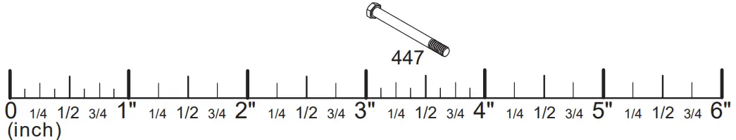
| 447 | 3/8″ X 4-1/4″ HEX BOLT | 4 |
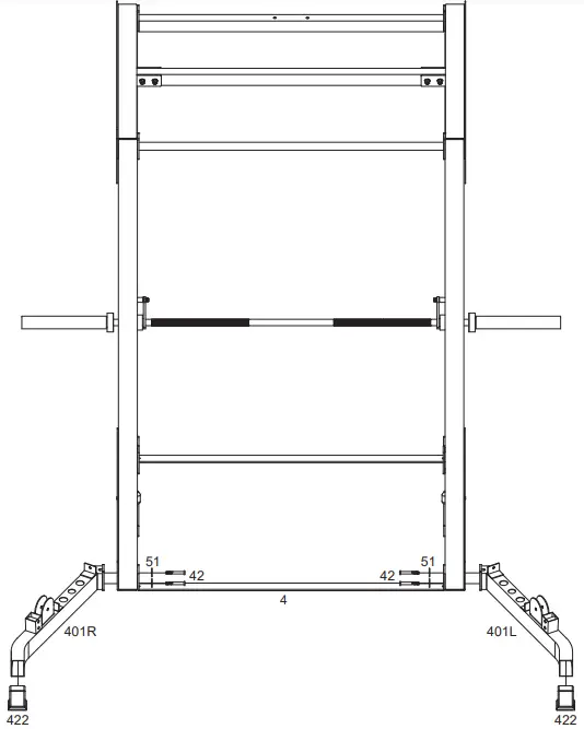
Base Frame Assembly
STEP 1
- To ease assembly, DO NOT tighten any bolts until instructed. Wherever we describe assembly for a right side component, please duplicate procedure for the left side.
- Remove two 3/8″ X 4″ Hex Bolts (42) on your Jones and attach Right Base Frame (401R) to The Jones. Reuse the hardware two 3/8″ X 4″ Hex Bolts (42) and two 3/8″ Washers (51) only. Please make sure that you thread whole 3/8″ X 4″ Hex Bolt (42) to the end. Attach 50mm Cap (422) to Right Base Frame (401R).

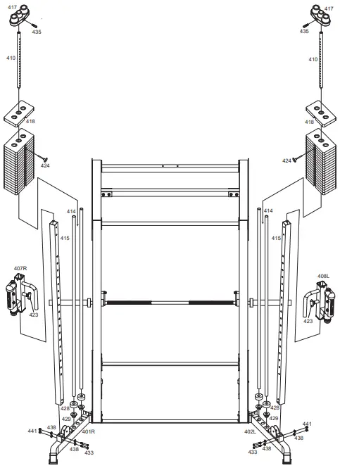
Weight Base Assembly
STEP 2
- Attach Upright Frame (415) to the Right Base Frame (401R), using two 3/8″ X 2-3/4″ Hex Bolts (433), four 3/8″ Washers (438) and two 3/8″ Nylon Nuts (441).
- Insert two Guide Rod Holders (429) to the Right Base Frame (401R) as shown.
- Insert the two Guide Rods (414) into the Guide Rod Holders (429) in the Right Base Frame (401R) and slide two Rubber Donuts (428) over top and down the Guide Rods (414).
- Slide the 10 lbs plate (418) {19 per side} over top and down the Guide Rod (414). Make certain that each plate is oriented with selector hole on bottom and facing forward. Attach the Top Plate (435) to the Selector Rod (410) using the Top Plate Bolt (435). Tighten Top Plate Bolt (435) with Hex Wrench (not provided). Screw the Pulley Bracket (409) into the Selector Rod (410), only about half way. This will be an adjustment point in the future. Slide Top Plate (417) over and down to the Guide Rods (414).
- Slide the Right Cable Height Adjuster (407R) over the top of the Upright Frame (415). Stop at your desired height by locking the Pop Pin (423).

Top Frame Assembly
STEP 3
- Loosen the pre-assembled two 5/16″ X 1/4″ Set Screws (437) in the ringlets on the Top Frame (403R) to allow it to easily slide onto the Guide Rods (414). Slide the Top Frame (403R) onto the Guide Rods (414). Attach Right Top Frame (403R) to Front Top Frame (2) of the Jones, re-using the two 3/8″ X 4-1/4″ Hex Bolts (447), two 3/8″ Washers (51) and two 3/8″ Nylon Nuts (55) originally used on the base Jones. Repeat for left side.
Tighten all Bolts.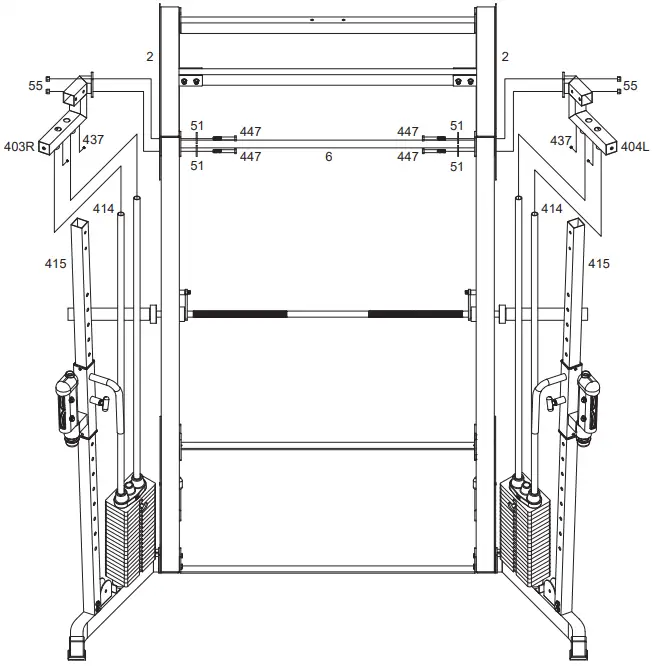
Top Panel Assembly
STEP 4
- Attach Right Top Panel (405R1 & 405R2), to the Right Top Frame (403R) as shown using five 3/8″ X 3″ Hex Bolts (432), ten 3/8″ Washers (438) and five 3/8″ Nylon Nuts (441). Repeat for left side.
Tighten all Bolts.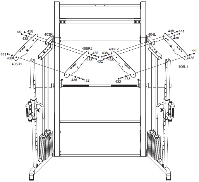
Top Cable Assembly
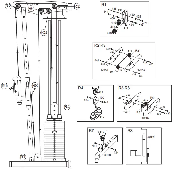
STEP 5
Assemble cables and pulleys simultaneously.
Pulleys are mounted using 3/8″ X 3″ Hex Bolts (432), 3/8″ Washers (438), and 3/8″ Nylon Nuts (441). Pay attention, as some places use washers, others don’t.
- Insert the threaded end of the Top Cable (416) between the pulleys in the front of the Right Cable Height Adjuster (407R) as shown Fig. R1. Route the cable up and over two top Pulleys at the Front and Rear of the Top Panel (405) as shown Fig. R2 & R3, then down to the Pulley Bracket (409) as shown Fig. R4.
- Continue routing over the two lower pulleys on the Top Panel (Fig R5 & R6) and then down to the pulley in the welded bracket on the Right Base Frame (401R) as shown in Fig R7. Screw the threaded end of the Top Cable (416) into the Bracket welded on the Right Cable Height Adjuster (407R) AT LEAST one third of the way. This is a cable adjustment area. When all cables have been tightened, make sure to secure the Jam Nut to prevent the Top Cable (416) from unscrewing.

Top Cable Assembly
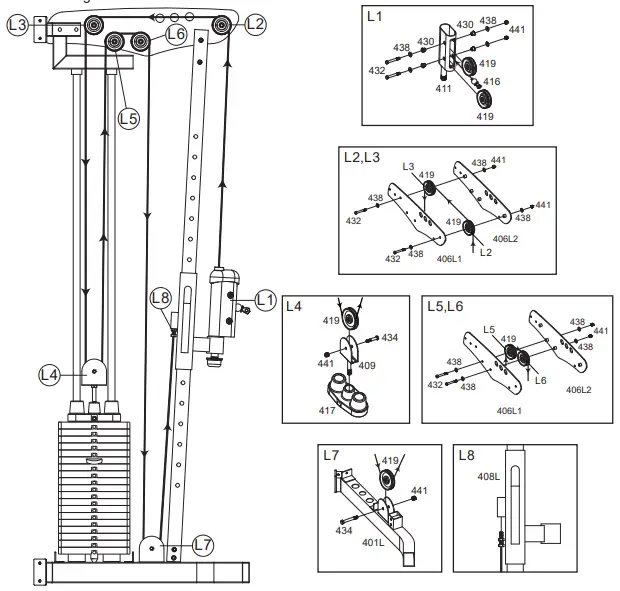
STEP 6
Assemble cables and pulleys simultaneously.
Pulleys are mounted using 3/8″ X 3″ Hex Bolts (432), 3/8″ Washers (438), and 3/8″ Nylon Nuts (441). Pay attention, as some places use washers, others don’t.
- Insert the threaded end of the Top Cable (416) between the pulleys in the front of the Left Cable Height Adjuster (408L) as shown Fig. L1. Route the cable up and over two top Pulleys at the Front and Rear of the Top Panel (406) as shown Fig. L2 & L3, then down to the Pulley Bracket (409) as shown Fig. L4.
- Continue routing over the two lower pulleys on the Top Panel (Fig L5 & L6) and then down to the pulley in the welded bracket on the Left Base Frame (402L) as shown in Fig L7. Screw the threaded end of the Top Cable (416) into the Bracket welded on the Left Cable Height Adjuster (408L) AT LEAST one third of the way. This is a cable adjustment area. When all cables have been tightened, make sure to secure the Jam Nut to prevent the Top Cable (416) from unscrewing.

Stack Shroud Assembly
STEP 7
- Attach Front & Rear Stack Shroud (412 & 413) and Trim for Shroud (446) to the Right Top Frame (403R) and Right Base Frame (401R) using four 5/16″ X 1/2″ Hex Threaded Bolts (436) and eight 5/16″ Washers (439).
- Change to “Repeat for left side.
Tighten all Bolts.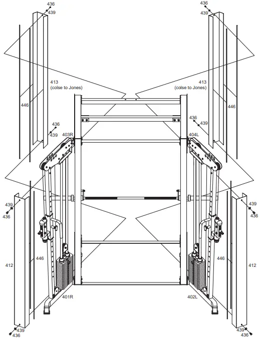
Assembly is complete! Please take the following steps before using the Jones Cable Functional Trainer Attachment :
- .Make certain all bolts are tightened securely.
- For better performance, apply a household lubricant (such as silicone) to VERTICAL GUIDE RODS(414).
- Always be certain that RIGHT & LEFT CABLE HEIGHT ADJUSTER(407R) are fully engaged when using Jones Cable Functional Trainer Attachment.
- Enjoy many years of a Fit Lifestyle.
Thank you for purchasing the Jones Machine System. If You have any questions, please call your local BodyCraft dealer or call our customer service department at 800-990-5556
Contact Us
![]() 800.900.5556
800.900.5556
[email protected]
WWW.BODYCRAFT.COM
![]() NODYCRAFT
NODYCRAFT
7699 GREEN MEADOWS DR.
LEWIS CENTER., OHIO 43035


