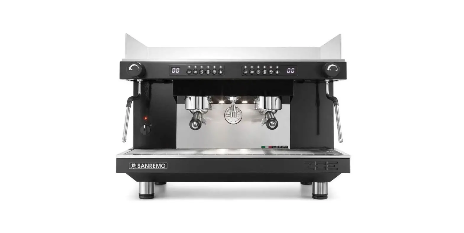
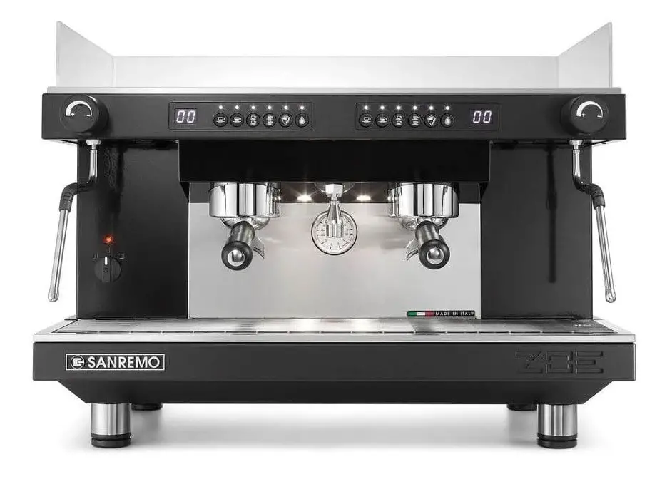
SANREMO ZOE Coffee Machine
FOREWORD
This manual is for use by qualified personnel and contains information and tips to use and keep your coffee maker as efficiently as possible. Please read all instructions very carefully before you actually use your machine to make sure the machine works properly and to ensure a long working life. Instructions are part of the product. Please keep this document. The appliance is not intended for use by persons (including children) with reduced physical or motor capabilities, or lack of experience and knowledge, unless they have been given supervision or instruction concerning use of the appliance by a person responsible for their safety. This booklet refers to the following models:
Model – ZOE SAP
Semi-automatic with continuous delivery and LED keypad. Available in 2 group version.
Model – ZOE SED
Electronic microprocessor-controlled model with quantities programmable by LED keypad. Available in 2 group version.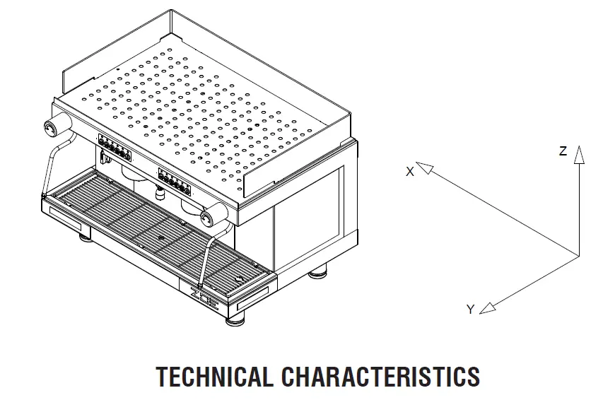
TECHNICAL CHARACTERISTICS
| GROUPS | 2 |
| WIDTH (X) mm | 720 |
| DEPTH (Y) mm | 528 |
| HEIGHT (Z) mm | 537 |
| CAPACITY litres | 10 |
| NET WEIGHT kg | 62,7 |
| GROSS WEIGHT kg | 65 |
| SUPPLY VOLTAGE V | 120 220-240 1N~ 380-415 3N~ |
| ABSORBED POWER RESISTOR (230V) kW | 2,95/4,9 |
| ABSORBED POWER CUP WARMER RESISTOR (optional) kW | 0,2 |
| ABSORBED POWER ELECTRIC PUMP kW | 0,2 |
| ABSORBED POWER EXTERNAL ELECTRIC PUMP kW | 0,2 |
| POWER SOLENOID VALVES kW | 0,0225 |
| ABSORBED POWER AUTOMATIC LEVEL REGULATOR kW | 0,01 |
| BOILER WORKING PRESSURE (1.8 Bar) MPa | 0,08:0,1 |
| MAINS WATER PRESSURE (MAX) (1-1.2 Bar) MPa | 0,6 |
| COFFEE DELIVERY PRESSURE (8-9 Bar) MPa | 0,8/0,9 |
The weighted sound pressure A of the appliance is less than 70 dB.
For correct operation and maintenance of the appliance you should follow this manual precisely, respecting the instructions and referring to the diagrams.
INSTALLATION
Before installing the appliance ensure that the mains voltage and power correspond to the data given in the specifications table. Take the appliance out of the packaging and put it in its final place of installation ensuring that it is stable and safe and that there is the necessary space for using it. Place the machine in a way that the distance between the grid and the floor is wider than 1,5 mt. To clean the internal circuit more efficiently, you are recommended to empty and fill the boiler a number of times and deliver simple water and coffee to be thrown away.
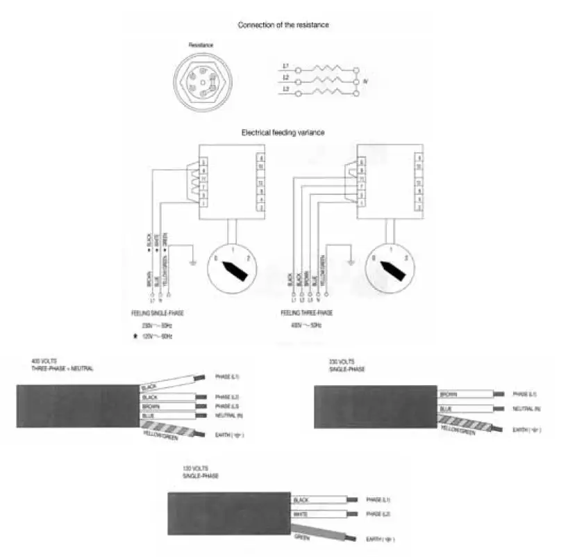
Electrical connection
Before connecting the power cable, follow the instructions below to install a safety switch and of the proper capacity:
Install ground cable, then phase cables. Uninstall phase cables first and then ground if needed.
Make sure the ground connection complies with existing standards and regulations.
To connect directly to the mains electricity supply, include a device to disconnect the appliance from the mains, with a contacts opening distance which allows complete disconnection in conditions of category III overtension, in compliance with the installation rules.
N.B. CHECK THAT THE DATA ON THE RATING PLATE CORRESPOND TO YOUR MAINS ELECTRICITY SUPPLY.
INSTALLING THE POWER SUPPLY CABLE
Water Connection
When installed, the boiler and heat exchangers are dry to avoid possible damage to the appliance caused by freezing.
- The appliance must be supplied with cold water only.
- If the mains pressure is higher than 0.6 Mpa (6 bars), you must install a pressure regulator with 0.6 Mpa (6 bars) maximum output pressure.
- Connect the drain hose to the drip tray, avoiding excessively tight curves and sloping the hose appropriately to facilitate water flow.
- Connect the 3/8” hose to the mains water supply, then to the water softener and the appliance.
Connect to the mains water supply in respect of national legislation.
N.B. The water softener is indispensable for correct operation of the appliance, to optimise coffee delivery in the cup and to extend the working life of components, as it purifies the water from limescale and residues that would otherwise shorten working life.
Failure to follow these instructions absolves the company from all liability.
Before connecting the pump intake tube, open the tap and run water through the water softener for about two minutes to eliminate possible.
IMPURITIES FILTER
The impurities filter (code 10355150) is normally mounted on the hose connecting the purifier to the pump (fig. A) to prevent impurities in the water from damaging downstream components such as the pumping head, flow pumps, solenoid valves, etc. The capsule filter (code 10355162) which blocks the impurities present in the water must be replaced about every three months.
The three-month period is indicative only as the actual length of time is correlated to water consumption and the impurities present in the mains water supply.
To replace the pod filter: unscrew the impurities filter (code 10355150) and replace the pod filter.
Before inserting the new pod filter, make sure the inside of the body (10355152 and 10355154) is completely clean.
Any foreign matter must be removed to ensure correct filtration.
The impurities filter must be mounted according to the flow direction indicated by the arrow (fig. A) on the body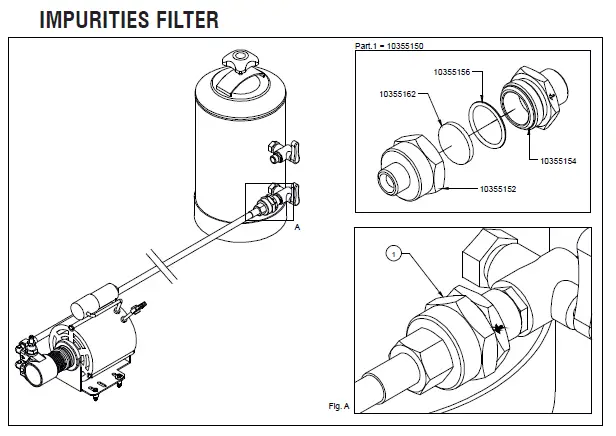
Use Preliminary Check
Before using the appliance, check that:
- the plug is inserted properly into the mains power outlet;
- the water filling hose is correctly connected to the mains water outlet, check for leaks and that the water tap is open;
- the drain pipe is positioned in accordance with the preceding instructions.
With the steam tap (B) open, place the ON/OFF switch (D) in the 1 position and wait for the water in the boiler to reach the maximum level established by the electronic control unit. If the boiler does not fill within the set time-out (90 secs.), the pump stops and the keypad LEDs flash. In this case put the on/off switch (D) to position 0 and then to position 1 to finish filling the boiler.
Now put the on/off switch (D) to position 2 so that the heating elements are powered and therefore start to heat the water.
Wait for steam to come out the steam nozzle (B), then close the tap and, using the Boiler pressure gauge, check that the pressure has reached and maintains a value of 0.8:1 bar. If it is not on this value, turn the adjusting screw on the pressure switch (+increase, – decrease, see figure below).
Hot Water Delivery
Make sure the boiler pressure gauge shows a pressure of 0.5:1 bars. Press the button (M6) to deliver hot water, then press again to stop delivery. Take great care to avoid burns.\
Steam Water Delivery
All models have two steam nozzles on the sides of the work surface, with the exception of the one group machine which has just one. These steam nozzles are retractable and can be oriented by means of a ball joint. To deliver steam, turn the knobs (B) anticlockwise. Take great care to avoid burns.
Coffee Delivery ZOE SAP MODEL
Insert the filter holder (E) into the group head (F) turning the filter holder counter-clockwise. Press the button (M5) and wait for the required quantity of coffee to be dispensed, press it again.
Coffee Delivery ZOE SAD MODEL
Insert the filter holder (E) in its seat (F) by turning it anticlockwise. Select the type of delivery required on the keypad (M):
M1=One short/standard coffee.
M2=One standard/long coffee.
M1=Two short/standard coffees.
M4=Two standard/long coffees.
M5=Electronic settings button or continuous manual delivery.
Before use, the operator must always check the indicator (L) to make sure that the level of water in the boiler is above the minimum level.
Dispenser Programming
- To access this phase keep the button M5 on the first pushbutton panel on the left pressed for over 5 seconds. The indicator lights of the buttons M5 start to blink continuously. Select the caption corresponding to the amount required and press to dispense. The indicator light of button M5 and that of the selected caption remain lit. When the required amount has been dispensed, press the selected dispensing button again so that the control unit stores the data. Repeat the above procedure for all 4 dispensing buttons on the pushbutton panel. A dispensed quantity may also be set for the hot water button (M6) by repeating the above procedure. Upon completion of the procedure, the remaining groups will automatically use the stored quantity. The other groups may, however, be programmed independently by repeating the same procedure as above after having programmed the first group on the left.
- There are 2 safety systems inside the control unit designed to protect the electronic system and the various parts of the appliance. If, upon pressing a dispensing button, the corresponding indicator light starts blinking, this indicates a malfunction in the electronic system or lack of water. For safety reasons, the dispensing of water stops after 4 minutes and in any case after 4 litres of water.
- The ZOE electronics also offers the possibility of reproducing the pre-brewing effect by wetting the coffee for 0.6 seconds and then stopping the subsequent brewing from starting for 1.2 seconds. This option is only applicable for single shots of coffee.
To Enable Pre-Brewing
With the appliance switched off, put the on/off switch (D) to position 1 and at the same time keep the button (M1) on the left-hand group pressed until the indicator light corresponding to the button (M5) remains lit; then release the button (M1). Now put the on/off switch (D) to position 0 and then to position 2 in order to store the operation.
To Disable Pre-Brewing
With the appliance switched off, put the on/off switch (D) to position 1 and at the same time keep the button (M2) on the left-hand group pressed until the indicator light corresponding to the button (M5) remains lit; then release the button (M2). Now switch the appliance off and then on again using the on/off switch (D) in order to store the operation.
CLEANING
Spout assembly filter: after having dispensed the last cup of coffee, the filter and filter holder must be washed with water. If they are damaged, worn or clogged, they should be replaced.
Drip tray and grid: the drip tray and grid should be removed frequently and coffee residues cleaned away.
Water softener: the softener should be periodically regenerated according to the manufacturer’s directions given in the instruction booklet.
External housing: the external housing and the steel parts should be cleaned with sponges and soft cloths to avoid scratching. Only use detergents that do not contain abrasive powders or solvents and do not use steel wool.
WARNINGS: when using the appliance it is recommended that the various instruments be kept under control, checking that they are in the previously indicated normal working conditions.
When the appliance has been left unused for a number of days, or every 2/3 months during normal use, to clean the internal circuits more efficiently, it is good practice to fill the boiler a number of times and deliver simple water and coffee to be thrown away.
APPLIANCE FAILURE
The user must check that this is not due to:
- power failure or blackout.
- lack of mains water supply or no water inside the boiler.
For any other causes, contact a qualified SANREMO After-Sales Service Centre.
BEFORE CARRYING OUT ANY WORK INSIDE THE APPLIANCE OR REMOVING ANY PART OF THE HOUSING, ALWAYS DISCONNECT FROM THE ELECTRICITY SUPPLY.
WARRANTY
Every purchased appliance (keep the receipt, invoice and delivery note) is covered by a statutory guarantee. This warranty envisages the replacement free of charge of parts that are shown to the service centre or manufacturer’s satisfaction to be defective due to faulty materials or workmanship and providing that the appliance has not been misused or tampered with by unauthorised persons or persons using incorrect components or techniques.
Any defective part shall be returned to the manufacturer.
NOTE: never activate the pump without water. Excessive heat will damage the pump and no warranty replacement is granted in that case.
WARNINGS
- The appliance must not be cleaned using a water jet.
- Do not put the appliance in water.
- The appliance must not be positioned near to any source of heat.
- The appliance is unsuitable for outdoor installation.
- Children must be supervised to make sure they do not play with the appliance.
- The appliance must be installed in places where its use and maintenance is limited to qualified persons only.
- Access to the service area is limited to persons with knowledge and practical experience of the appliance, particularly as regards safety and hygiene aspects.
- To ensure safe use the appliance must be in a level position.
- If the power cable is damaged, have it replaced by a SANREMO After-Sales Service Centre, since a special tool is required for this purpose. The appliance must be used in rooms with a temperature between 5°C and 35°C.
- IN THE EVENT OF FAILURE OR MALFUNCTION, REQUEST SERVICE ONLY FROM QUALIFIED PERSONNEL AT THE AFTER-SALES SERVICE CENTRE.
- The data and features indicated in this booklet are not binding on the manufacturer, which reserves the right to make changes to its models at any time.
- The manufacturer shall not be under any liability for injury to persons or damage to property arising from failure to comply with the instructions given in this booklet.
INFORMATION FOR USERS
- In accordance with article 13 of legislative decree no. 151 “Implementation of directives 2002/95/EC, 2002/96/EC and 2003/108/EC on restriction of the use of certain hazardous substances in electrical and electronic equipment and the disposal of waste”.
- The appliance or packaging is marked with the symbol of a bin with a cross to indicate that at the end of its working life it must be disposed of separately from other waste.
- A separate collection of this appliance at the end of its working life is organised and managed by the manufacturer.
- The user wanting to dispose of this appliance should therefore contact the manufacturer and follow the separate waste collection system to dispose of the appliance at the end of its working life.
- The appropriate separate collection and the subsequent recycling, treatment and ecological disposal of the disused appliance help avoid possible negative effects on the environment and health and encourage the re-use and/or recycling of the constituent materials.
- The unlawful disposal of the product by the user is punishable by the administrative sanctions provided for by the legislation in force at the time.

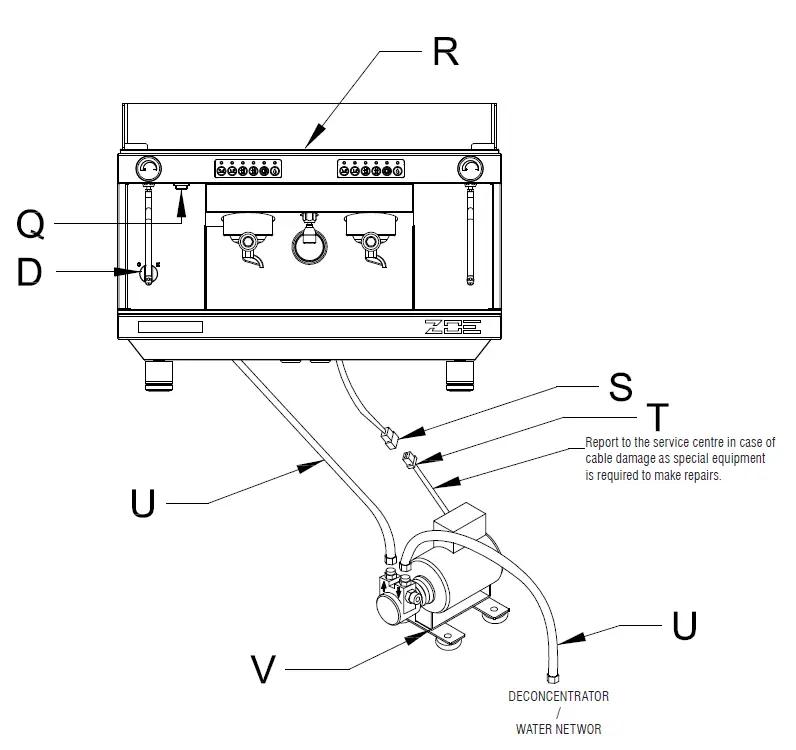
LEGEND
- D – MAIN SWITCH
- 0 – OFF
- 1 – PUMP AND AUTOMATISMS ON
- 2 – PUMP, AUTOMATISMS AND ELECTRIC HEATING ON
- Q – CUP WARMER ON/OFF SWITCH
LIT – ON
NOT LIT = OFF - R – CUP WARMER RESISTOR
- S – 3-WAY BLOCK FEMALE
- T – 3-WAY BLOCK MALE
- U – WATER FILL DRIVE HOSE
- V – EXTERNAL PUMP
Connect the external pump stably on its feet.
The pump must be kept away from sources of heat or water.
Warning – correct use of rotary pumps
- Proper Alignment of Pump and Motor
On occasion the noise of a motor-pump assembly is caused by a poor alignment.
When the coupling between motor and pump is rigid, the pump rotor and the motor rotor may be out of axis. If this condition is maintained over time the most likely damage is seizure of the pump.
An efficient solution of this problem is the use of an elastic coupling between pump and motor. Fluid-o Tech supplies an optional kit code N. 10051020.
- Quality of Water.
Tight mechanical tolerances of components and materials used for rotary vane pumps require a very clean water, free from suspended particles. Sand, deposits on connecting pipes or the resins of the sweetener, when flowing through the pump, may scratch graphite parts causing problems of insufficient pressure and flow rate. If a closed loop hydraulic circuit is not available to guarantee a clean water and no sources of contamination Fluid-o-Tech recommend to install a 5-10 micron filter between the sweetener and the pump. Recommended filter: food approved polipropilene wire cartridge. Keep the filter clean.: an upstream dirty filter will create cavitation and the pump will break shortly (see section 4). - Dry operation
Rotary vane pumps may operate in dry condition only for a very short time- few seconds! Without a proper water cooling the temperature of the mechanical seal will increase very quickly with resulting breakage. The most likely impact is a remarkable leak visible from the four drain holes close to the motor clamp . For potential lack of feed from city water line Fluid-o-Tech recommend the installation of a minimum pressure safety switch upstream from the pump. In case of feed from a tank install on the tank a minimum level switch - Cavitation
Cavitation shows when feed flow rate does not match the pump design requirement: most frequent causes are dirty filters, small diameter pipes,more users on the same line. Opening of the safety valve (generally installed upstream from pump and filter) must happen before the pump start up. This will avoid cavitation. For the same reason closing of the safety valve must be delayed after the pump shut down. The most noticeable effect is an increase of noise. If cavitation continues the impact is the same as of dry operation - Back Feed of Hot Water
If a non return valve between the pump and the hot water vessel is defective the pump may come in contact with hot water(90-100°C). Dimensional
variations of components will cause seizure of the pump - Wrong connections
Pumps connectors are 3/8”NPT(conical) or 3/8” GAS(cylindrical). Connectors with thread different from the recommended type are occasionally used. Sealing is made with a glue or with teflon tape. If the connector is forced it is possible to create beards; if excess sealing glue is used the extra quantity of glue may enter into the pump body. In both cases it is likely to create a damage. - Pressure strokes
To avoid pressure strokes opening of solenoid valves installed downstream must happen before the start of the pump. For the same reason closing of the valve must be delayed after stopping of the pump. A pressure stroke may break graphite parts and damage mechanical seal causing blockage of the pump and leaks - Handling
A crash on the floor may create deformations that will jeopardize the tight mechanical tolerances of the pump components. For the same reason be
very careful when clamping the pump to mount or demount connectors. - Scale build up
Scale deposits will quickly show on inner components when using hard water, not sweetened with ion exchange resins. Scale formation increases when the pressure relief valve is used as flow rate regulator: the rate of scale deposition increases with increasing of closed loop circulation. Scale deposits cause an increase of torque, occasional seizure of the pump or a reduction of operating pressure because the pressure relief valve cannot work properly.
To minimize this problem Fluid-o-Tech suggest to use pumps with flow rate matching the hydraulic circuit features. In some circuits it is advisable to periodically remove scale with a chemical treatment
MOD. ZOE 2GR SED / SAP
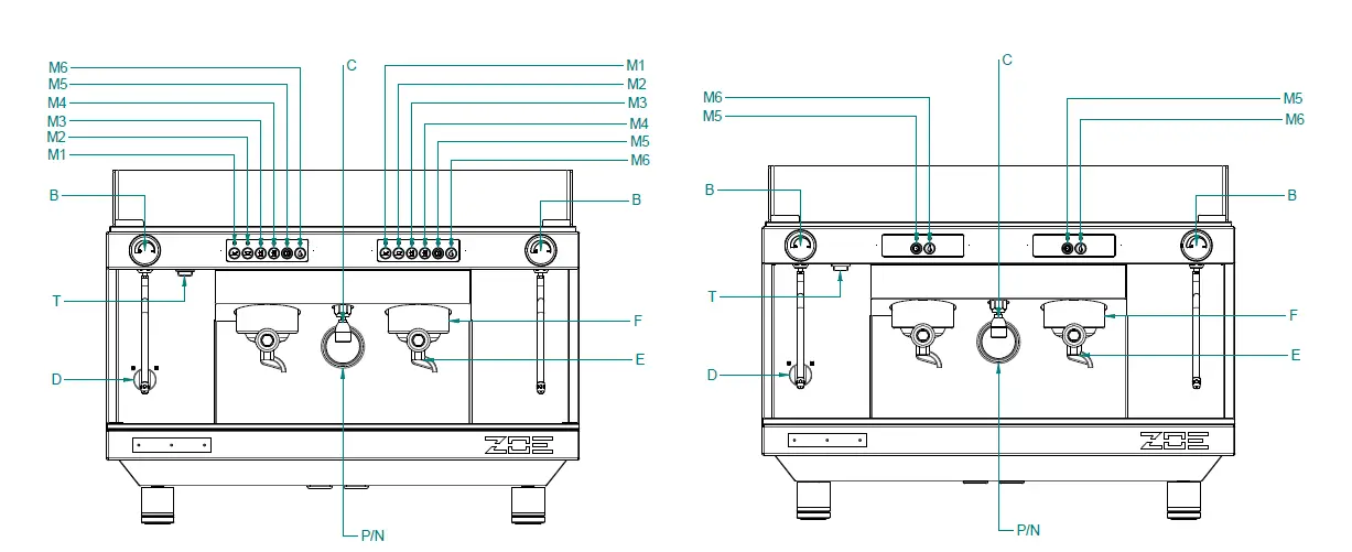
- B – Steam tap knob
- C – Water tap knob
- D – On/off switch
- 0 – Off
- 1 – Pump and automatic devices on
- 2 – Pump, automatic devices and heating element on
- E – Filter holder
- F – Filter holder group head
- I – Dispense – stop button
- M1 – One strong coffee
- M2 – One weak coffee
- M3 – Two strong coffees
- M4 – Two weak coffees
- M5 – Continual dispensing and programming key
- M6 – Hot water
- N – Pump pressure gauge
- P – Boiler pressure gauge
- T – Cup warmer switch (Optional)
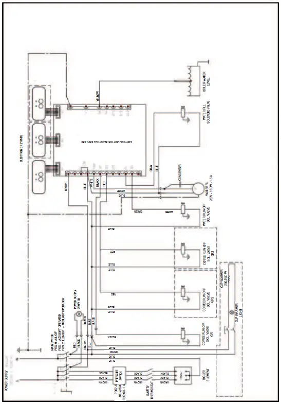
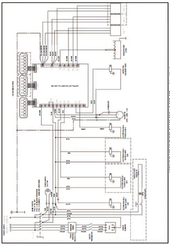
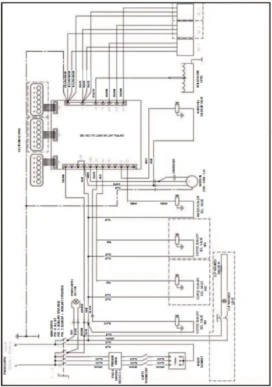
WIRING DIAGRAM
THREE-PHASE ZOE 1-2-3GR SAP update 03/12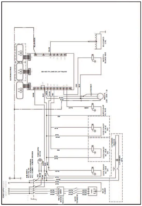
WATER DIAGRAM
ZOE 1-2-3GR UPDATE 03/2012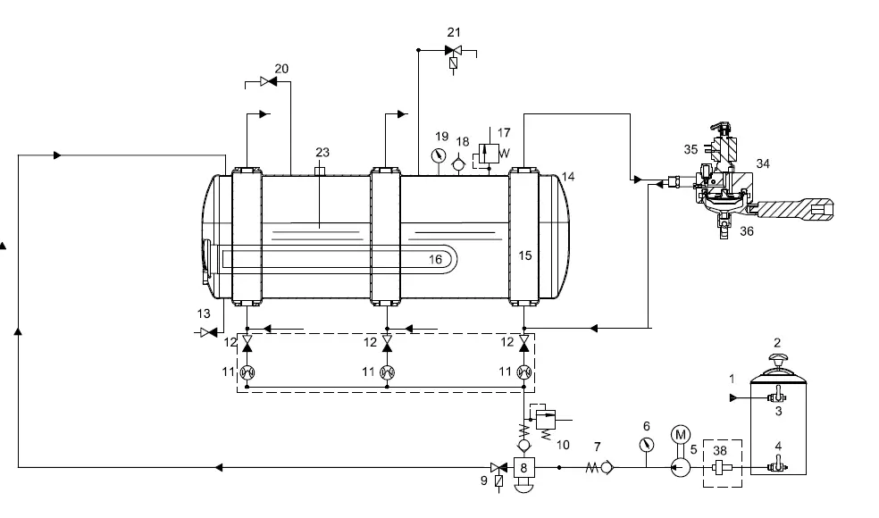
LEGEND
- Water supply
- Softener
- Water in tap
- Water out tap
- Pump and electric motor
- Pressure gauge (boiler pressure)
- Check valve
- Filling block with filter
- Solenoid valve for automatic fill
- Expansion valve
- Volumetric meter
- Fill tap
- Boiler drain tap
- Boiler
- Heat exchanger
- Boiler resistor
- Safety valve
- Vacuum breaker valve
- Pressure gauge (boiler pressure)
- Steam tap
- Hot water run-off solenoid valve
- Level sensor 1-2Gr
- Pressure switch
- Spout group
- Spout group solenoid valve
- Filter holder
- Filter
Esploded view
MOD ZOE update 03/12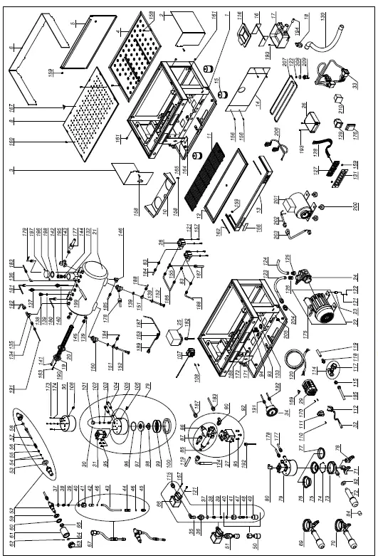
| POS. | COD. | DESCRIPTION |
| 1A | 10017302 | FRAME ZOE 2GR MATT BLACK |
| 1B | 10017304 | FRAME ZOE 2GR WHITE |
| 2A | 10017372 | PANEL RH ZOE GLOSSY BLACK |
| 2B | 10017374 | PANEL RH ZOE RED |
| 2C | 10017376 | PANEL RH ZOE PURPLE |
| 2D | 10017378 | PANEL RH ZOE MATT BLACK |
| 2E | 10017380 | PANEL RH ZOE PEARL WHITE |
| 2F | 10017382 | PANEL RH ZOE YELLOW |
| 2G | 10017384 | PANEL RH ZOE GREEN |
| 3A | 10017392 | PANEL RH ZOE GLOSSY BLACK |
| 3B | 10017394 | PANEL RH ZOE RED |
| 3C | 10017396 | PANEL RH ZOE PURPLE |
| 3D | 10017398 | PANEL RH ZOE MATT BLACK |
| 3E | 10017400 | PANEL RH ZOE PEARL WHITE |
| 3F | 10017402 | PANEL RH ZOE YELLOW |
| 3G | 10017404 | PANEL RH ZOE GREEN |
| 4 | 10017324 | TOP TANK ZOE 2GR ST. |
| 5A | 10017332 | REAR PANEL ZOE 2GR GLOSSY BLACK |
| 5B | 10017334 | REAR PANEL ZOE 2GR RED |
| 5C | 10017336 | REAR PANEL ZOE 2GR PURPLE |
| 5D | 10017338 | REAR PANEL ZOE 2GR MATT BLACK |
| 5E | 10017340 | REAR PANEL ZOE 2GR PEARL WHITE |
| 5F | 10017342 | REAR PANEL ZOE 2GR YELLOW |
| 5G | 10017344 | REAR PANEL ZOE 2GR GREEN |
| 6 | 10352430 | CUP RETAINER ZOE 2GR TRANSPARENT |
| 8 | 10017326 | TOP GRILLE ZOE 2GR |
| 10A | 10017352 | PROTECT. GROUPS ZOE 2 GLOSSY BLACK |
| 10B | 10017354 | PROTECT. GROUPS ZOE 2 RED |
| 10C | 10017356 | PROTECT. GROUPS ZOE 2 PURPLE |
| 10D | 10017358 | PROTECT. GROUPS ZOE 2 MATT BLACK |
| 10E | 10017360 | PROTECT. GROUPS ZOE 2 PEARL WHITE |
| 10F | 10017362 | PROTECT. GROUPS ZOE 2 YELLOW |
| 10G | 10017364 | PROTECT. GROUPS ZOE 2 GREEN |
| 11 | 10017328A | DRAIN GRILLE ZOE 2GR FILINOX |
| 12 | 10017322 | DRIP TRAY ZOE 2GR |
| 13A | 10017472 | BOTTOM FRONT PANEL 2GR MATT BLACK |
| 13B | 10017474 | BOTTOM FRONT PANEL ZOE 2GR WHITE |
| 14 | 10017320 | FRONT PROTECTION ZOE 2GR |
| 15 | 10352065 | TELESCOPIC FOOT D50X55 INOX |
| 16 | 10012144 | FLOW REGULATOR FOR DRIP TRAY |
| 17 | 10022441 | UNIVERSAL DRIP TRAY |
| 18 | 10806099 | HOSE CLIP INOX |
| 19A | 10455050 | RESISTOR 1950W 230V 1GR |
| 19B | 10455051 | RESISTOR 1950W 120V 1GR |
| 19C | 10455052 | RESISTOR 2700W 230V 2GR |
| 19D | 10455053 | RESISTOR 2700W 120V 2GR |
| 19E | 10455054 | RESISTOR 5100W 230V 3GR |
| 19F | 10455060 | RESISTOR 2400W 230V 1GR |
| 19G | 10455065 | RESISTOR 2400W 120V 1GR |
| 19H | 10455080 | RESISTOR 4500W 230V 2GR |
| 20 | 10502020 | WASHER D56X41X2mm PTFE |
| 21 | 10002670 | BOILER COPPER 2GR 10 LITRES D. 190 |
| 22A | 10252079A | EL. MOTOR 150W 120V 1-2GR |
| 22B | 10252080A | EL. MOTOR 150W 230V 1-2GR |
| 22C | 10252086 | EL. MOTOR 165W 230V 2-3GR |
| 22D | 10252094 | EL. MOTOR 150W 230V CB 2-3GR |
| 22E | 10252098 | EL. MOTOR 130W 230V CB VENTILATED 1-2GR |
| 23 | 10255022 | VIBRATION DAMPER PUFFER |
| 24A | 10252070B | ROTARY PUMP 150L/H 1-2GR |
| 24B | 10252072B | ROTARY PUMP 204L/H 2-3GR |
| 25 | 10602010A | PRESSURE SWITCH |
| 26A | 10112012 | CONTROL UNIT XLC SED 120V |
| 26B | 10112072E | CONTROL UNIT XLC SED 230V |
| 26C | 10112083C | CONTROL UNIT ON-OFF 1-2-3GR XLC |
| 27 | 10303093A | 2-WAY SOLENOID VALVE BAS. 32X32 230V |
| 28 | 10112134 | VOLUMETRIC METER 1/8” |
| 29A | 10122050 | JUMPER SWITCHER SINGLE PHASE |
| 29B | 10122060 | JUMPER SWITCHER THREE PHASE |
| 30 | 10052028A | SPOUT ASSY. RING WITH FILTER DISK AND GASKET E61 |
| 31A | 10302066 | 3-WAY SOLENOID VALVE BAS. 32X32 230V |
| 31B | 10305555 | 3-WAY SOLENOID VALVE BAS. 32X32 120V |
| 32A | 10553021 | INDICATOR LIGHT ORANGE D6 230V WIRED |
| 32B | 10553024 | INDICATOR LIGHT ORANGE D6 120V WIRED |
| 33A | 10102560 | WIRING ZOE 2GR SED WITH RING ASSY. |
| 33B | 10102570 | WIRING ZOE 2GR SAP WITH RING ASSY. |
| 34 | 10552018 | PRESSURE GAUGE |
| 35 | 10852210 | L-UNION 2020 1/8″ F/M |
| 36 | 10859029 | REDUCER UNION 1/8″M 3/8″M CHROMED MI |
| 37 | 10402056A | OR 2062 VITON |
| 38 | 10402043 | SWIVEL JOINT SPRING |
| 39 | 10402054 | SWIVEL JOINT CAP |
| 40 | 10402082 | LANCE SWIVEL JOINT OR D10 |
| 41 | 10402282 | STEAM LANCE NUT MLX |
| 42 | 10402288 | LANCE BALL JOINT MLX |
| 43 | 10402274 | STEAM TUBE POLISH. INOX STEAM LANCE RM |
| 44 | 10753052 | ANTI-BURN JOINT |
| 45A | 10402276 | NOZZLE INOX 2 SIDE HOLES |
| 45B | 10402279 | NOZZLE INOX 4 HOLES |
| 46 | 10402081 | LANCE TUBE OR MLX |
| 47 | 10402266 | BALL JOINT INOX WATER 1/8” M |
| 48 | 10505018 | OR D.7.2X1.9 EPDM OR6 BOILER OUTLET |
| 49 | 10402140 | BOILER OUTLET |
| 50 | 10402143 | BOILER WATER OUTLET SHORT COMPL. |
| 51 | 10401982 | WATER TAP COMPL. ZOE 230V |
| 52 | 10402120A | TAP BODY |
| 53 | 10505561 | TAP BUSH COPPER |
| 54 | 10505121 | TAP ROD OR NBR |
| 55 | 10402015 | TAP SHAFT BUSH |
| 56 | 10402014 | TAP SHAFT SPRING |
| 57 | 10402061 | CENTRAL TAP SHAFT |
| 58 | 10505558 | TAP SHAFT GASKET |
| 59 | 10803547 | WASHER D20 FLAT ZN |
| 60 | 10806312 | TOOTHED WASHER D21 ZN |
| 61 | 10092164A | STEAM KNOB ROMA |
| 62 | 10806370B | TAP SPLIT PIN |
| 63 | 10092162A | STEAM KNOB CAP ROMA |
| 64 | 10402040 | TAP WASHER BRASS |
| 65 | 10402028 | HALF NUT 1/2″ CHR. RAISED |
| 66A | 10303060A | 2-WAY SOLENOID VALVE 1/8″ 120V UL-CSA |
| 66B | 10303086 | 2-WAY SOLENOID VALVE 1/8″230V |
| 67 | 10402484A | STEAM LANCE COMPL. RM-VM-ZOE D.10 |
| 69 | 10402310C | FILTER HOLDER ASSY. 1 CUP 1,3 |
| 70 | 10402312B | FILTER HOLDER ASSY. 2 CUP 1,3 |
| 71 | 10052085 | SPOUT 2-WAY, OPEN |
| 72 | 10091150 | FILTER HOLDER HANDLE VR-RM |
| 73 | 10052034 | FILTER HOLDER BODY |
| 74 | 10052055 | FILTER RETAINER SPRING 1,3 |
| 75A | 10052100 | FILTER 1 CUP |
| 75B | 10052101 | FILTER 1 CUP 6GR POD MOD. |
| 76 | 10052110 | FILTER 2 CUP |
| 77 | 10052220 | BLIND FILTER |
| 78 | 10052075 | SPOUT 1-WAY, OPEN |
| 79A | 10052206A | RING ASSY. CA GDE61 230V |
| 79B | 10052208A | RING ASSY. CA GDE61 120V |
| 80 | 10255028A | ELBOW UNION ROT. F1/8 |
| 81 | 10852030A | ELBOW UNION 1020 6-1/8″ |
| 82 | 10091154 | FILTER HOLDER HANDLE RING VR-RM |
| 83 | 10852080A | STRAIGHT UNION 1050 6-1/8″M |
| 84 | 10091152 | FILTER HOLDER HANDLE CAP VR-RM |
| 85 | 10355172 | ROUND MESH FILTER |
| 86 | 10056058A | FILLING BLOCK BODY LIGHT |
| 87 | 10655557 | EXPANSION VALVE |
| 90 | 10255058 | ELBOW UNION ROTATING 1/8M |
| 92 | 10056110 | FILLING BLOCK ASSY. 230V LIGHT |
| 93 | 10105022 | CABLE GLAND PA268 |
| 94 | 10105024 | SCREW TC+ 3.5X25 ZN CABLE GLAND |
| 95 | 10805071 | SCREW TCEI M4X10 A2 |
| 96 | 10502070A | OR 3187 EPDM FDA |
| 97 | 10052248 | MAZZOCCO RING ASSY. FOR GASKET AND FILTER DISK E61 |
| 98 | 10052141 | DIFFUSER GR. E61 |
| 99 | 10052120 | MESH BOILER OUTLET GR. E61 |
| 100 | 10502110 | UNDERCUP GASKET GR. E61 |
| 101 | 10052142 | CLOSURE CAP GIGLEUR GR. RING |
| 102 | 10052143 | TOP CAP GASKET GR. RING |
| 103 | 10052135 | GIGLEUR HOLE GR. D.0.8 |
| 104 | 10852033 | EXTENSION NI CA GR. RING |
| 105 | 10052136 | FILTER ASSY. E-61/RING |
| 106 | 10805078 | SCREW TCEI M6X8 A2 |
| 107 | 10111015 | THERMOSTAT WITH MAN. RESET |
| 108 | 10805872 | SCREW TC+ M4X6 ZN |
| 110 | 10805116 | SCREW TC+ M3X10 ZN TRUC. BLACK SWITCHER KNOB |
| 111 | 10122015 | SWITCHER KNOB |
| 112 | 10105190 | 2-WAY BLOCK F. |
| 114 | 10402059 | DRAIN TAP WITH KNOB |
| 115 | 10852050A | STRAIGHT UNION 1050 8-1/8″M |
| 116 | 10022476 | DRIP TRAY COVER |
| 117 | 10402060 | BOILER DRAIN TAP KNOB |
| 118 | 10853058 | STRAIGHT HOSE CONNECTION 1510 6-1/8″M |
| 119 | 10905010 | SILICONE HOSE TRANSP. |
| 120A | 10102190 | POWER CABLE 3X2.5 MT3 N5 SINGLE PHASE |
| 120B | 10102191 | POWER CABLE 5X2.5 MT3 N4 THREE PHASE |
| 120C | 10102193 | POWER CABLE 3X4 MT3 N7 |
| 120D | 10102196 | POWER CABLE 3x12AWG SJOOW 3MT |
| 120E | 10102197 | POWER CABLE 3x14AWG SJOOW |
| 121 | 10803519 | TOOTHED WASHER D4.2 ZN |
| 122 | 10805512 | NUT 4MA MEDIUM ZN |
| 123 | 10852484 | DRIVE HOSE L=2000 |
| 124 | 10852470 | DRIVE HOSE L=450 |
| 125 | 10852290A | STRAIGHT UNION 1050 10-3/8″M |
| 126 | 10852293A | STRAIGHT UNION 1050 8-3/8″M |
| 127A | 10112268 | KEYPAD TO 6 KEYS SED |
| 127B | 10112274 | KEYPAD TO 2 KEYS SAP |
| 128A | 10112078 | CABLE, PIN TO PIN, 600mm |
| 128B | 10112079 | CABLE, PIN TO PIN, 800mm |
| 129 | 10556041A | CUP WARMER SWITCH RED |
| 130 | 10852460 | SPIRAL DRAIN HOSE L.2 MT |
| 131A | 10017412 | KEYPAD SUPPORT SED ZOE BLACK |
| 131B | 10017414 | KEYPAD SUPPORT SED ZOE WHITE |
| 131C | 10017432 | KEYPAD SUPPORT SAP ZOE BLACK |
| 131D | 10017434 | KEYPAD SUPPORT SAP ZOE WHITE |
| 132 | 10022552 | SAFETY VALVE TANK COPPER |
| 133 | 10105030 | CABLE GLAND IN BLACK RUBBER |
| 134 | 10852580A | STRAIGHT UNION 1050 6-1/4″M |
| 135 | 10852821 | UNION 2070 T M/F/F 1/4″ |
| 136 | 10852250A | ELBOW UNION 1020 6-1/4″M |
| 137 | 10112042 | LEVEL SENSOR 140mm CA 2GR |
| 138 | 10652040A | BOILER AIR VENT VALVE |
| 139 | 10852180 | WASHER 1/4″ COPPER |
| 140 | 10853053A | INTAKE TUBE 1/4″M |
| 141 | 10106060 | JUMPER RESISTOR COPPER |
| 142 | 10652012 | SAFETY VALVE |
| 143A | 10052174 | GIGLEUR HOLE D2.5 |
| 143B | 10052176 | GIGLEUR HOLE D3 |
| 143C | 10052178 | GIGLEUR HOLE D3.5 |
| 143D | 10052179 | GIGLEUR HOLE D2 |
| 144 | 10806324 | WASHER 3/8″ COPPER |
| 145 | 10852540 | CAP 2611 1/4″M |
| 146 | 10852060A | ELBOW UNION 1020 8-1/4″M |
| 150 | 10853298 | BOTT. HEAT EXCHANGER UNION 1/4″-3/8″-3/8″ |
| 151 | 10852240A | UNION 1170 6-1/4″ |
| 152 | 10042040 | INJECTOR PTFE D.8 |
| 153 | 10852780 | T-UNION 2090 1/8 M/F/M |
| 155 | 10852028A | T-UNION 1010 6-6-1/8″M |
| 156 | 10803344 | SCREW TSP+ M4X10 A2 |
| 157 | 10805074 | SCREW TE M4X8 ZN |
| 158 | 10805027A | SCREW TBL+ M4x10 A2 |
| 159 | 10809011 | FLANGED NUT 4MA |
| 160 | 10805022 | SCREW TBL- M4X20 A2 |
| 161 | 10405540 | BALL PRESSER |
| 162 | 10017490 | ANTIFRICTION PLATE |
| 163 | 10806050 | NUT M4 X RESISTOR |
| 164A | 10952051B | RATING PLATE AL. SAN REMO 230V |
| 164B | 10952052B | RATING PLATE AL. SAN REMO 400V |
| 164C | 10952053A | RATING PLATE AL. SAN REMO 120V |
| 165 | 10805950 | SHEAR RIVET D3x6 |
| 166 | 10955060C | LABEL SAN REMO 117.5X19.4X2M |
| 167 | 10955013 | TRIANGULAR HOT SURFACE LABEL |
| 168 | 10955025A | TRIANGULAR EARTH LABEL |
| 169 | 10955015 | TRIANGULAR VOLTAGE LABEL |
| 170 | 10805038 | SCREW TSP+ M3X6 A2 |
| 171 | 10809012 | FLANGED NUT 6MA |
| 172 | 10803536 | TOOTHED WASHER D6.2 ZN |
| 173 | 10805075 | SCREW TE M5X8 ZN |
| 174 | 10803520 | TOOTHED WASHER D5.3 ZN |
| 175A | 10252038 | MOTOR CONDENSER 150W |
| 175B | 10252040 | CONDENSER 10 MF 450VL MOTOR 165W |
| 176 | 10105243B | TRANSPARENT SWITCH CAP |
| 177 | 10003050 | TUBE TOP HEAT EXCHANGER CA 2 DLX |
| 178 | 10003052 | TUBE BOTT. HEAT EXCHANGER CA 2 DLX |
| 179 | 10003224 | STEAM HOSE RH ZOE 2 |
| 180 | 10003222 | STEAM HOSE LH ZOE 2 |
| 181 | 10003226 | HOT WATER RUN-OFF HOSE ZOE 2 |
| 182 | 10003220 | PRESS. SW. TUBE ZOE 2 |
| 183 | 10003160 | BOILER FILL HOSE CA DLX 2 |
| 184 | 10003166 | FILL HOSE 1°GR CA 2 DLX SED CB |
| 185 | 10003228 | BOILER DRAIN HOSE ZOE 2 |
| 186 | 10002060 | JUMPER TUBE 1°-2°VOLUM. CA 2 SED |
| 187A | 10003162 | FILL HOSE VOLUM. CA1-2 DLX SED CB |
| 187B | 10003170 | FILL HOSE GR CA DLX-MI 2 SAP CB |
| 188 | 10003168 | FILL HOSE 2°GR CA 2 DLX SED CB |
| 189 | 10003172 | JUMPER TUBE 1°-2°GR CA DLX SAP CB |
| 190 | 10809024 | WASHER D.4.3 COPPER |
| 191 | 10002028 | BOILER PRESS. SW. CAPILLARY TUBE PI |
| 192 | 10002021 | PUMP PRESS. SW. CAPILLARY TUBE VE |
| 193 | 10805084 | SCREW TC+ M4X10 ZN |
| 194 | 10052064 | DRIP TRAY CAP |
| 195 | 10853296 | TOP HEAT EXCHANGER UNION 3/8″-3/8″ |
| 196 | 10022554 | SAFETY VALVE TANK COVER COPPER |
| 197 | 10022556 | SCREW TC+ 2.9X4.5 ZN TANK COPPER |
| 198 | 10503018 | PISTON ASSY. GASKET SILICONE |
| 199 | 10905024 | SILICONE HOSE D12X18 |
| 200 | 10352058 | EXTERNAL PUMP FOOT |
| 201A | 10252087 | EL. MOTOR 300W 230V P.E 1-2GR |
| 201B | 10252089 | EL. MOTOR 187W 230V P.E. 2-3GR |
| 201C | 10252096 | EL. MOTOR 150W 230V P.E. 1-2-3GR CB |
| 202 | 10102595A | CONNECT. WIRING MACHINE/EXT. PUMP |
| 203 | 10102620A | CONNECT. WIRING MOTOR E.P. 2GR |
| 204 | 10355150 | FILTER PUMP CONNECTION 3/8″ |
| 205 | 10112105 | SERIAL OUTPUT CABLE RS232 |
| 206 | 10102566 | CUP WARMER WIRING ZOE 2GR |
| 207 | 10455122 | CUP WARMER RESISTOR 2GR D6.4 |
SANREMO s.r.l.
Via Bortolan, 52
Zona Industriale Treviso Nord 31050 Vascon di Carbonera (TV) tel. +39 0422 448900
fax +39 0422 448935
www.sanremomachines.com


