![]()
EXPRESS LUCK INDUSTRIAL (SHENZHEN) LIMITED
User Manual
Model Name: SKI.WB7638U.1_MT7668BU
REVISION HISTORY
| VERSION | DATE | BOARD ID | PAGE | DESCRIPTION | AUTHOR |
| V0 | 2019.07.23 | TD.MS6886.762 A19267 | All | First Issued. | Stannis |
Installation Guidance
The final host/module combination may also need to be evaluated against the FCC Part 15B criteria for unintentional radiators in order to be properly authorized for operation as a Part 15 digital device. The user’s manual or instruction manual for an intentional or unintentional radiator shall caution the user that changes or modifications not expressly approved by the party responsible for compliance could void the user’s authority to operate the equipment. In cases where the manual is provided only in a form other than paper, such as on a computer disk or over the Internet, the information required by this section may be included in the manual in that alternative form, provided the user can reasonably be expected to have the capability to access information in that form. To ensure compliance with all non-transmitter functions the host manufacturer is responsible for ensuring compliance with the module(s) installed and fully operational. For example, if a host was previously authorized as an unintentional radiator under the Declaration of Conformity procedure without a transmitter-certified module and a module is added, the host manufacturer is responsible for ensuring that the after the module is installed and operational the host continues to be compliant with the Part 15B unintentional radiator requirements.
FCC Statement
This device complies with Part 15 of the FCC Rules. Operation is subject to the following two conditions:
- this device may not cause harmful interference, and
- this device must accept any interference received, including interference that may cause undesired operation.
Caution:
The user is cautioned that changes or modifications not expressly approved by the party responsible for compliance could void the user’s authority to operate the equipment.
Note: This equipment has been tested and found to comply with the limits for a Class B digital device, pursuant to part 15 of the FCC Rules. These limits are designed to provide reasonable protection against harmful interference in a residential installation. This equipment generates uses and can radiate radio frequency energy and, if not installed and used in accordance with the instructions, may cause harmful interference to radio communications. However, there is no guarantee that interference will not occur in a particular installation. If this equipment does cause harmful interference to radio or television reception, which can be determined by turning the equipment off and on, the user is encouraged to try to correct the interference by one or more of the following measures:
- Reorient or relocate the receiving antenna.
- Increase the separation between the equipment and receiver.
- Connect the equipment into an outlet on a circuit different from that to which the receiver is connected.
- Consult the dealer or an experienced radio/TV technician for help.
If power exceeds the limit and the distance (Over 20cm distance in actual use between the device and user) is compliant with the requirement FCC RF Radiation Exposure Statement:
This equipment complies with FCC radiation exposure limits set forth for an uncontrolled environment. This equipment should be installed and operated with a minimum distance of 20cm between the radiator and any part of your body. The device must be professionally installed The intended use is generally not for the general public.It is generally for industry/commercial use. The connector is within the transmitter enclosure and can only be accessed by disassembly of the transmitter which is not normally required. the user has no access to the connector. Installation must be controlled. Installation requires special training
Canada Statement
This device contains license-exempt transmitter(s)/receiver(s) that comply with Innovation, Science, and Economic Development Canada’s license-exempt RSS(s). Operation is subject to the following two conditions:
- This device may not cause interference.
- This device must accept any interference, including interference that may cause undesired operation of the device.
| Frequency (MHz) | Antenna Type | Antenna Gain (dBi) |
| 2412-2462 | FPC Antenna | 2.3 |
| 2402-2480 | FPC Antenna | 2.3 |
| 5180-5825 | FPC Antenna | 2.3 |
Warning: Changes or modifications to this unit not expressly approved by the party responsible for compliance could void the user’s authority to operate the equipment.
Notice to OEM integrator
Must use the device only in host devices that meet the FCC/ISED RF exposure category of mobile, which means the device is installed and used at distances of at least 20cm from persons.
The end-user manual shall include FCC Part 15 /ISED RSS GEN compliance statements related to the transmitter as shown in this manual.
The host manufacturer is responsible for compliance of the host system with the module installed with all other applicable requirements for the system such as Part 15 B, ICES 003.
The host manufacturer is strongly recommended to confirm compliance with FCC/ISED requirements for the transmitter when the module is installed in the host.
Must have on the host device a label showing Contains FCC ID: 2AWY6-MT7668BU, IC: 26332-MT7668BU
STANDARD CONFIGURATION
| FRONT VIEW | 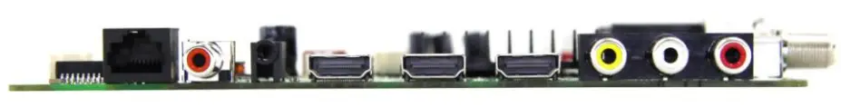
|
| SIDE VIEW | 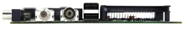 |
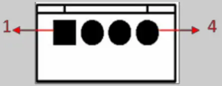
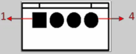
BOARD PICTURE
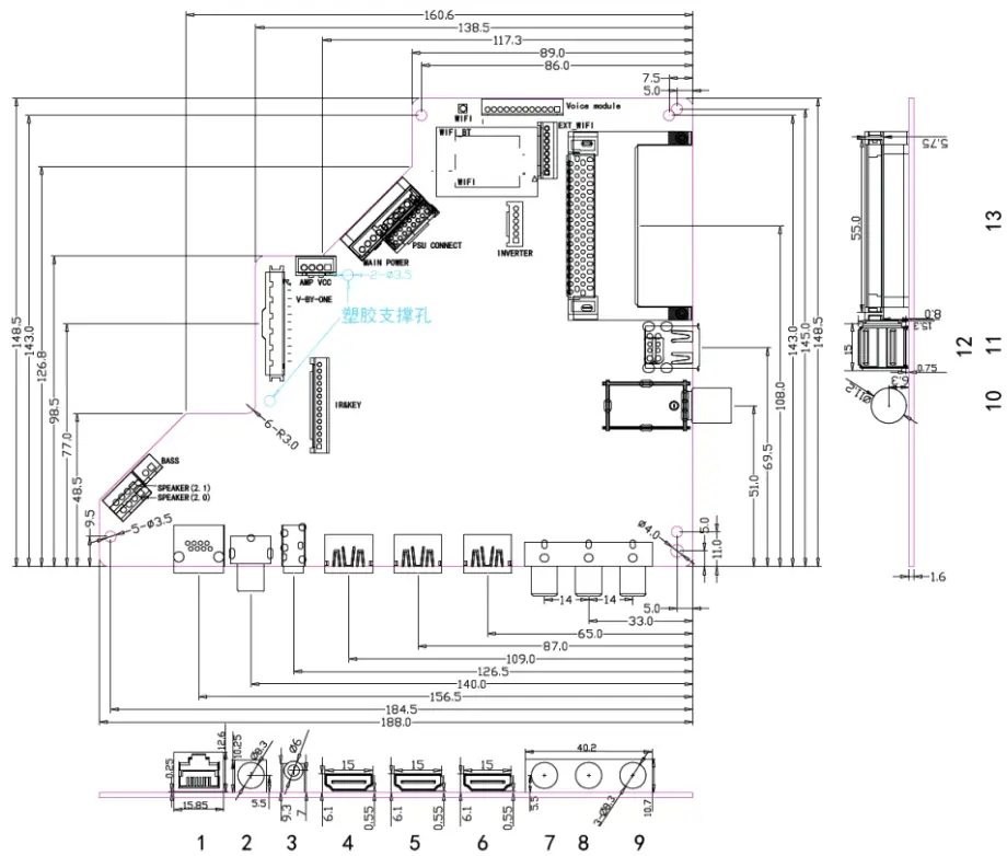
Size:188mm(L)*148.5mm(W)*1.6mm(H)
| NO. | Description |
| 1 | Rk145 I N |
| 2 | COAX OUT |
| 3 | EARPHONE OUT |
| 4 | HDM 11 I N (2.0) |
| 5 | 1101412 i N (2. o) |
| 6 | HDIA I 3 I N (2. 0) |
| 7 | CVBSIN |
| 8 | CVBS L I N |
| 9 | CVBS R I N |
| 10 | RF I N (S/S2) |
| 11 | RF I N (T/T2) |
| 12 | USB1 I N |
| 13 | USB2 I N |
| 14 | ci SLOT |
FEATURES
| MAIN CHIPSET | MSD6886NQHA-8-00H8 | ||
| PANEL | Panel Type | TFT LCD | |
| Interface | V-by-one | ||
| Max Resolution | 3840*2160 | ||
| VIDEO INPUT | TV | ATV(PAL,SECAM)/DTV(DVB-T/C/T2/S/S2) | |
| ATVNTSC)/DTV(ATSC) | |||
| CVBS | Video System | PAL/NTSC | |
| Video level | 1.0 Vp-p±10% | ||
| HDMI | 480i, 480p, 720p, 1080i, 1080p, 2160P | ||
| *CEC, *ARC(HDMI 3), 4K2K(HDMI 1&2&3) | |||
| AUDIO INPUT | CVBS | L/R RCA input | 0.2 – 2.0VRMS |
| AUDIO OUTPUT | Earphone | Earphone output | 130 ~ 150mVRMS |
| COAX | PCM/RAW | ||
| Frequency response | Speaker | 100Hz-15KHz @±3dB(1KHz 0dB reference signal) | |
| Earphone | 150Hz-15KHz @±3dB(1KHz 0dB reference signal) | ||
| Max Output power | 2 x 8W(8Ω) | THD+N<10%@1KHz (Power Supply:12~24V,Audio Input: 0.5VRMS) | |
| 2 x 15W(6Ω) | |||
| 2ch ≦2 x 10W, 0.1ch ≦15 W(6Ω) | |||
| POWER TO PANEL | 12V | ||
| RJ45 NETWORK | 10/100M auto-identification and DHCP | ||
| Management | Standby Power Consumption < 0.2W(Board Only) | ||
| USB FUNCTION | software upgrade, multimedia play | ||
| Button Types | Ground Key Interface | ||
| Note: 1. Licenses involved in the specifications above are supposed to be obtained by customers themselves. 2. When 3.3V panel Irush≥1000mA, Inormal≥600mA, please contact CVTE engineers to confirm 3.3V panel power supply component selection. 3. Max current of USB2.0: 500mA. Large impact current of USB device(exceeds 500mA) may lead to board abnormal work; 4. The normal operating current of the 5V panel is ≤ 1500mA. | |||
3.1 ELECTRICAL CHARACTERISTICS & REQUIREMENTS
| Symbol | Voltage Range | Ripple | Total current | MAX. current(mA) of Individual part | |||||||
| MIN | TYP | MAX | Voltage | Mainboard | AMP | USB | MHL | Panel | DVD | ||
| 24V | 22 | 24 | 26 | 500mVP-P | 1.7A | — | 1.7A | — | — | — | — |
| 12V | 11 | 12 | 13 | 300 MVP-P | 2A | 0.5A | — | — | — | 1.5A | — |
| 5V | 4.9 | 5 | 5.3① | 120 MVP-P | 1.5A | 0.5A | — | 1A | — | — | — |
| 5VSB | 4.9 | 5 | 5.3① | 120mVP-P | 1.5A | 1.5A | — | — | — | — | — |
| Note①: Don’t exceed 5.25V when making the certification practice test. Note②: CtN = The sum of MAX. current(mA) of an individual part. | |||||||||||
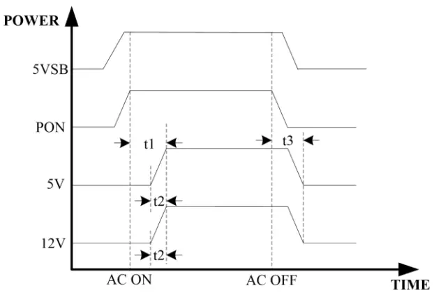
| Alternation | Description | MIN | MAX | Unit |
| t1 | Startup time | 0 | 100 | mS |
| t2 | Rise time | 0 | 50 | mS |
| t3 | The drop time of voltage | 0 | 200 | mS |
SCHEMATICS OF IR & KEYBOARD
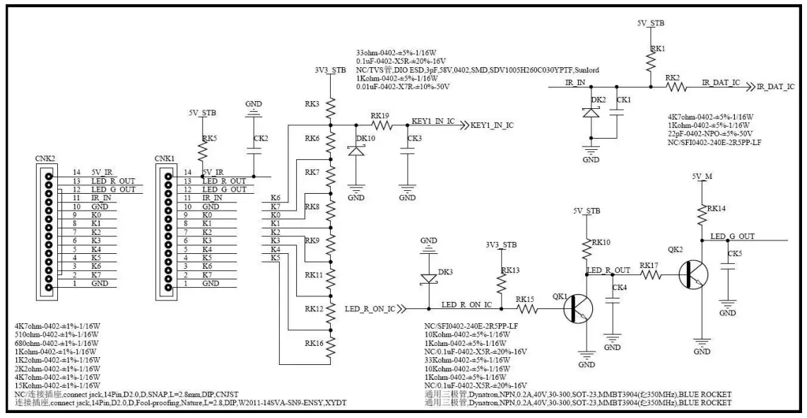
KEY FUNCTION: TV/AV, MENU, VOL+, VOL-, CH+, CH-, POWER
Note: The dividing resistor which is corresponding to the power key must be zero(equivalent to the voltage is zero).
Otherwise, the board will not work. K6 is the default power.
INTERFACE DEFINITION
The optional connectors and terminals are marked with
◆ CNA6(4PIN/2.50): SPEAKER(2.0) CONNECTOR 1
 | ||
| NO. | SYMBOL | DESCRIPTION |
| 1 | ROUT+ | Audio Right Channel Output+ |
| 2 | LOUT+ | Audio Left Channel Output- |
| 3 | BASS- | BASS Output- |
| 4 | BASS+ | BASS Output+ |
◆ *CNA4(4PIN/2.50): SPEAKER(2.1) CONNECTOR 2
 | ||
| NO. | SYMBOL | DESCRIPTION |
| 1 | ROUT+ | Audio Right Channel Output+ |
| 2 | ROUT- | Audio Right Channel Output- |
| 3 | LOUT- | Audio Left Channel Output- |
| 4 | LOUT+ | Audio Left Channel Output+ |
◆ *CNA8(2PIN/2.50): BASS CONNECTOR
 | ||
| NO. | SYMBOL | DESCRIPTION |
| 1 | BASS- | BASS Output- |
| 2 | BASS+ | BASS Output+ |
◆ CNW8A (51PIN/0.5): V-BY-ONE CONNECTOR (V-BY-ONE) Note: FFC
 | ||
| NO. | SYMBOL | DESCRIPTION |
| 1 | GND | Ground |
| 2 | VBY7P | V-by-One HS Data Lane 7 |
| 3 | VBY7N | V-by-One HS Data Lane 7 |
| 4 | GND | Ground |
| 5 | VBY6P | V-by-One HS Data Lane 6 |
| 6 | VBY6N | V-by-One HS Data Lane 6 |
| 7 | GND | Ground |
| 8 | VBY5P | V-by-One HS Data Lane 5 |
| 9 | VBY5N | V-by-One HS Data Lane 5 |
| 10 | GND | Ground |
| 11 | VBY4P | V-by-One HS Data Lane 4 |
| 12 | VBY4N | V-by-One HS Data Lane 4 |
| 13 | GND | Ground |
| 14 | VBY3P | V-by-One HS Data Lane 3 |
| 15 | VBY3N | V-by-One HS Data Lane 3 |
| 16 | GND | Ground |
| 17 | VBY2P | V-by-One HS Data Lane 2 |
| 18 | VBY2N | V-by-One HS Data Lane 2 |
| 19 | GND | Ground |
| 20 | VBY1P | V-by-One HS Data Lane 1 |
| 21 | VBY1N | V-by-One HS Data Lane 1 |
| 22 | GND | Ground |
| 23 | VBY0P | V-by-One HS Data Lane 0 |
| 24 | VBY0N | V-by-One HS Data Lane 0 |
| 25 | GND | Ground |
| 26 | LOCKN_TX | Lock detect |
| 27 | HTPDN_TX | Hot Plug Detect |
| 28 | Bit_SEL | ‘H’ or NC=10bit(D) ‘L’=8bit |
| 29 | AGE | ‘H’ or NC: AGP |
| 30 | LD_EN | Local Dimming Enable(default for High)for Panel |
| 31 | Bit_SEL_1 | ‘H’ or NC=10bit(D) ‘L’=8bit |
| 32 | I2C_WP | I2C Write Protection/No Connection |
| 33 | SCL | I2C Clock signal |
| 34 | SDA | I2C Data signal |
| 35 | PCID_EN | PCID_EN |
| 36 | D_Fomat1 | Input Data Format [1:0] ‘00’=Mode 1,‘01’=Mode 2, ‘10’=Mode 3,‘11’=Mode 4, |
| 37 | D_Fomat0 | |
| 38 | GND | Ground |
| 39 | GND | |
| 40 | GND | |
| 41 | GND | |
| 42 | GND | |
| 43 | VCC_PANEL | Power Supply for Panel |
| 44 | VCC_PANEL | |
| 45 | VCC_PANEL | |
| 46 | VCC_PANEL | |
| 47 | VCC_PANEL | |
| 48 | VCC_PANEL | |
| 49 | VCC_PANEL | |
| 50 | VCC_PANEL | |
| 51 | VCC_PANEL | Power Supply for Panel |
◆ CNA1(4PIN/2.50): AMP VCC CONNECTOR
 | ||
| NO. | SYMBOL | DESCRIPTION |
| 1 | GND | Ground |
| 2 | GND | |
| 3 | 12/24V | +12/24V Power Supply for Amplifier |
| 4 | 12/24V | |
◆ CNK1(14PIN/2.0): IR & KEY CONNECTOR
 | ||
| NO. | SYMBOL | DESCRIPTION |
| 1 | GND | Ground |
| 2 | K7 | Key7(Reserved) |
| 3 | K6 | Key6 |
| 4 | K5 | Key5 |
| 5 | K4 | Key4 |
| 6 | K3 | Key3 |
| 7 | K2 | Key2 |
| 8 | K1 | Key1 |
| 9 | K0 | Key0 |
| 10 | GND | Ground |
| 11 | IR | IR Receiver, VIH≥2V, VIL≤ 1V, IILmin : 1mA, IIHmin :1mA |
| 12 | GRN | Green Indicator, VOH≥2V (IOMHAX: 2mA), VOL≤0.8V (IOLMAX: 2mA ) |
| 13 | RED | Red Indicator, VOH≥2V (IOHMAX: 1.3mA), VOL≤0.8V (IOLMAX: 0.5mA ) |
| 14 | 5V | +5V DC Power Supply |
◆ CN102(10PIN/2.54): MAIN POWER CONNECTOR
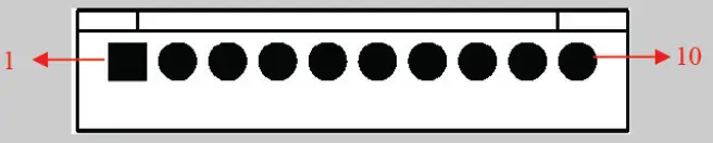 | ||
| NO. | SYMBOL | DESCRIPTION |
| 1 | 12V | +12V DC Power Supply |
| 2 | GND | Ground |
| 3 | 5V_M | Main +5V Power Supply |
| 4 | 5V_M | |
| 5 | PVCC | +5V/12V Power Supply for Panel |
| 6 | PVCC | |
| 7 | GND | Ground |
| 8 | GND | |
| 9 | PON | Power On/Off, VOH≥3V (IOHMAX: 2mA), VOL≤0.8V (IOLMAX: 0mA ) |
| 10 | 5VSB | +5V Power Supply when Standby |
◆ *CN103(2×8PIN/2.0): PSU CONNECTOR
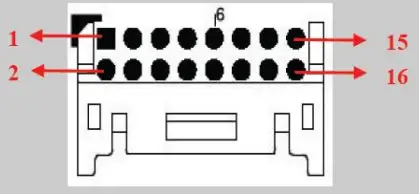 | ||
| NO. | SYMBOL | DESCRIPTION |
| 1 | 12V/24V | Power Supply for Amplifier |
| 2 | 12V/24V | |
| 3 | GND | Ground |
| 4 | ||
| 5 | 12V_M | +12V Power Supply |
| 6 | 12V_M | |
| 7 | GND | Ground |
| 8 | 12V_M | +12V Power Supply |
| 9 | GND | Ground |
| 10 | ||
| 11 | 5V_M | +5V Power Supply |
| 12 | 5V_M | |
| 13 | PON | Power On/Off, VOH≥3V (IOHMAX: 2mA), VOL≤0.8V (IOLMAX: 0mA ) |
| 14 | 5VSTB | +5V Power Supply When the standby |
| 15 | BLO | Back-Light ON/OFF Control for Panel, VOH≥3V (IOHMAX: 1mA), VOL≤0.8V (IOLMAX: 1mA ) |
| 16 | ADJ | Brightness Adjustment for Panel, VOH≥3V (IOHMAX: 1mA), VOL≤0.8V (IOLMAX: 1mA ) |
◆ *CN66(12PIN/2.0): Voice Module CONNECTOR
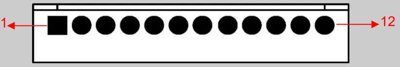 | ||
| NO. | SYMBOL | DESCRIPTION |
| 1 | Voice_DP | USB+ |
| 2 | Voice_DM | USB- |
| 3 | GND | Ground |
| 4 | TV_USB_Interrupt | TV USB Interrupt |
| 5 | NC | No Connection |
| 6 | NC | |
| 7 | NC | |
| 8 | NC | |
| 9 | TV_Interrupt | TV Interrupt |
| 10 | TV_Enable | TV Enable |
| 11 | GND | Ground |
| 12 | Voice_PWR | 3.3V or 12V Power |
◆ *CNU62(8PIN/2.0): EXT-WIFI CONNECTOR
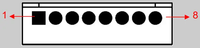 | ||
| NO. | SYMBOL | DESCRIPTION |
| 1 | RST | WIFI Reset |
| 2 | PWR | +5V Power Supply for WIFI |
| 3 | DM | WIFI Data- |
| 4 | DP | WIFI Data+ |
| 5 | GND | Ground |
| 6 | BT_HOST_WAKE | Bluetooth Wake |
| 7 | WL_HOST_ WAKE | WIFI Wake |
| 8 | NC | No Connection |
◆ CN2(6PIN/2.0): INVERTER CONNECTOR
 | ||
| NO. | SYMBOL | DESCRIPTION |
| 1 | GND | Ground |
| 2 | GND | |
| 3 | ADJ | Brightness Adjustment for Panel, VOH≥3V (IOHMAX: 1mA), VOL≤0.8V (IOLMAX: 1mA ) |
| 4 | BLO | Back-Light ON/OFF Control for Panel, VOH≥3V (IOHMAX: 1mA), VOL≤0.8V (IOLMAX: 1mA ) |
| 5 | 12V_M | +12V DC Power Supply |
| 6 | 12V_M | |
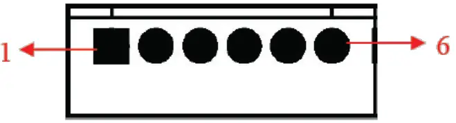
◆ CN5: UART CONNECTOR
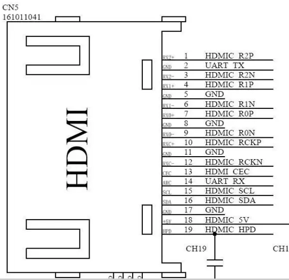 | ||
| NO. | SYMBOL | DESCRIPTION |
| 2 | GND | UART_TX |
| 14 | ARC | UART_RX |
CONFIGURATION & GENERAL PRECAUTIONS
- Relative humidity: ≤ 80%.
- Storage temperature: -10~60°C.
- Operation temperature: 0~40°C.
- Protect the board from static electricity in case of damage to the IC.
- Keep the board away from the conductor when it is working.
- Do not press the PCBA during transportation or placement.
- Do not bend or deform the board during the whole machine assembling, especially when connecting the cable.
- Do not plug or unplug the cable while the board is working..
- Clean the board with a soft dry cloth when it’s dirty.
- Don’t power it on before the panel is correctly connected.
- The whole machine certification performance will be subject to the impact of the whole machine, must use the whole machine to test and confirm.
- When using the I2C interface to communicate with the outside, please confirm the matching of the pull-up resistance and the series resistance with the CVTE hardware engineer.
- To ensure communication properly between the mainboard and external expansion modules, it’s recommended that test-related control and communication signals and power supply voltage waveform after installing the prototype to confirm whether it meets the relevant requirements
DECLARATION
- The product’s USB supports most the storage devices. If the device is not recognized, it may be caused by the device driver.
- Please refer to the specification for the value of voltage and current which is supplied by the USB slot, and the value is related to the loads of the 5V LCD panel. Due to the difference between the USB standard protocol and the interface specification of the device, the device may not be recognized by the TV player correctly.
- The difference in device and device capacity may lead to the TV player’s reading speed slowing down temporarily.
- Please don’t plug the USB device while the file is being read.
- Due to the differences in USB’s compatibility and stability, please initialize the system if the image stopped or does not function.
- If the hard disk cannot be recognized, please power on the hard disk with an external power supply or change the wire to a shorter USB2.0 wire.
NOTICE REGARDING TV MEDIA FORMAT AND
INTERFACE TECHNOLOGY
| Media type | Interface technology and others | ||
| Dolby Digital Decoder | MPEG2/MPEG4 | HDMI | Hbbtv2.0 |
| Dolby Digital Plus Decoder | AMR-NB | HDCP | Netflix |
| Dolby MS11 | AMR-WB | Wi-Fi | Freeview Play |
| Dolby MS12 | DRA | USB | NTFS |
| Dolby Atmos | AAC/HEAAC | MHL | Seraphic Open Browser |
| Dolby Vision | H.264 | Bluetooth | Seraphic TV Portal |
| DTS Sound | H.265 | NFC | - |
| DTS TruSurround | DivX | DVB-T2 | - |
| DTS HD | RMVB | DVB-S2x | - |
| DTS 2.0+Digital Out | WMA | ATSC | - |
| DTS Express 5.1 | WMA Pro | PlayReady | - |
| DTS Studio Sound | dbx-tv | MSS | - |
| DTS Studio Sound II | - | Widevine | - |
Introduction
This document is used to specify media formats, interface technologies, and others that may be involved in TV products.
| Media Format | Interface Technology & Others | ||
| Dolby Digital Decoder | MPEG2/MPEG4 | HDMI | Hbbtv2.0 |
| Dolby Digital Plus Decoder | AMR-NB | HDCP | Netflix |
| Dolby MS11 | AMR-WB | Wi-Fi | Freeview Play |
| Dolby MS12 | DRA | USB | NTFS |
| Dolby Atmos | AAC/HEAAC | MHL | Seraphic Open Browser |
| Dolby Vision | H.264 | Bluetooth | Seraphic TV Portal |
| DTS Sound | H.265 | NFC | - |
| DTS TruSurround | DivX | DVB-T2 | - |
| DTS HD | RMVB | DVB-S2x | - |
| DTS 2.0+Digital Out | WMA | ATSC | - |
| DTS Express 5.1 | WMA Pro | PlayReady | - |
| DTS Studio Sound | dbx-tv | MSS | - |
| DTS Studio Sound II | - | Widevine | - |
Notice
In the event, the LCD TV Driver Boards (“Boards”) are purchased or customized by your good company include any hardware(e.g. TV master chip, output connector) and/or software that support the above-mentioned media formats, interface technologies & others that may involve third-party technologies or intellectual properties, your company is hereby kindly reminded as follows:
- The product price under the sale contracts between us does not include any royalties, licensing fees, or expenses payable to the IP right holders for acquiring the right to use the third-party technologies or the license of the third party’s intellectual properties which may be involved due to the Boards’ and relating TV sets’ supporting the above-mentioned media formats, interface technologies & others. If the IP rights holders so request you shall obtain a valid license from the right holders and make payment at your own cost for such license.
- If your company requests to reduce or cancel the media formats or interface technologies & others supported by the Boards, you shall, upon your confirmation of the board’s specifications, or upon payment of the contract price, whichever is earlier, notice us such requests in writing.
- In the event the “Boards” purchased or customized by your good company do not include hardware and/or software that supports part or entire of the above-mentioned media formats and interface technologies & others, this Notice shall not be applicable to your company with respect to the media formats and interface technologies & others that are not supported by the Boards.
- The hardware, software, and technologies related to the media formats and interface technologies & others that may be involved in the Boards are all provided by third parties. We may update this Notice from time to time. If you find any omissions, please do not hesitate to let us know.
Regarding the TV mainboard Products (following referred to as “the Mainboard”), the technical requirements which are wholly listed and defined under this Letter of Confirmation for Product Technical Requirements, due to the fact that it was ultimately confirmed and determined by the buyer regarding the software program to the Mainboard, and the Mainboard’s features and functions (including patented features and functions, whether the features and functions are realized and practiced through the hips embodied in the Mainboard, the Mainboard itself, or through the TV sets embodying the Mainboard), the buyer shall be responsible for obtaining appropriate licenses from the relating intellectual property right holders and other right holders, acquiring appropriate permissions to use the software program to the Mainboard, obtaining appropriate permissions to realize and practice the relating features and functions of the Mainboard, reporting the transaction data, arranging the payment of royalties, and performing other duties and responsibilities which are necessary to use, sell, offer for sale, import or otherwise to dispose of the Mainboard with programmed software without infringing the intellectual property rights of any third party.
As our company is a specialized TV mainboard supplier and unable to acquire the performance or specifications requirements of the TV sets embodying the Mainboard, we hereby guarantee that the TV mainboard products supplied by our company are in conformance with the Letter of Confirmation for Product Technical Requirements which was confirmed in writing by both parties, and your company shall be responsible for the testing, debugging, tuning of the TV sets embodying the Mainboard, application for certifying the Mainboard and the TV sets embodying the Mainboard and performing other duties and responsibilities which are necessary for complying with the law and regulations of the countries and regions, where the Mainboard and the TV sets embody the Mainboard was imported and sold.![]()


