![]() HT10-Kit Rapid Shutdown Transmitter
HT10-Kit Rapid Shutdown Transmitter
Installation Guide
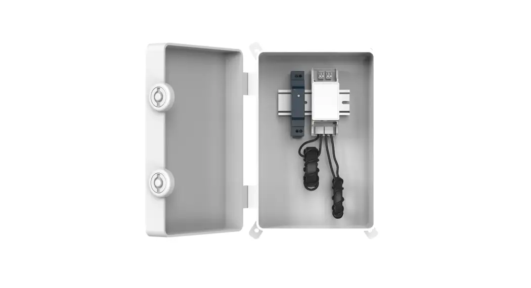
Appearance
- Transmitter
- Din Rail PSU
- Core 1
- Core 2
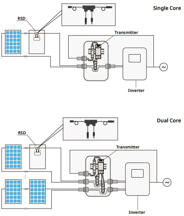
System Solution
Installation
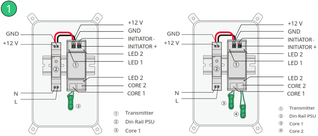 | |
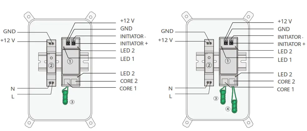
| • Mount Transmitter and power supply on DIN rail. • Connect DC leads from power supply to Transmitter. • Connect Core to Transmitter. If there is only one core need to connect, please connect Core 1 first. | Note: • 85-264VAC or 180-550VAC PSU can be used. • 180-550VAC PSU isolation class I requires grounding. • 85-264VAC PSU isolation class II does not require grounding. |
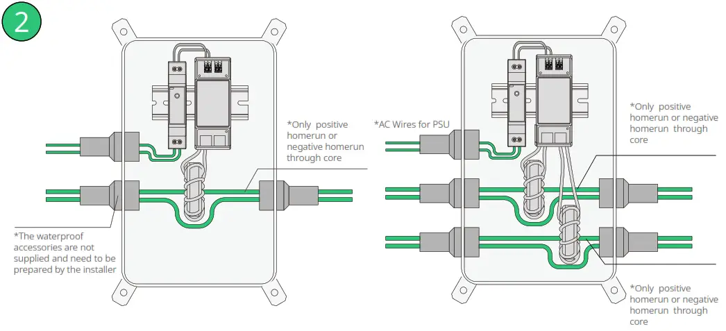 | |
| • Pass either positive home run or negative home run through Cores. • Connect wires to AC side of power supply. Note: • Install HRSD before powering on Transmitter. • Transmitter power supply must be on same AC branch circuit as inverter to meet rapid shutdown requirements. • When PV system is operating, the Power LED1 should be lit and the Signal LED2 should be blinking. • Place rapid shutdown system label no more than 1m (3ft) from Transmitter or AC disconnect if not at the same location. | Note: • Max. number of strings per Core*: 5 (75A core) or 15 (150A core) • Max. current per Core: 75A or 150A • Max. cable length from inverter (+) to inverter (-): 1000ft (300m) * With Φ 6 mm DC cable diameter (without DC connector) |
![]() © 2022 Hostiles Power Electronics Inc. All rights reserved.
© 2022 Hostiles Power Electronics Inc. All rights reserved.
Region: Global
AP040561 REV1.1


