NOTIFIER NION-232-MNNA Board Installation Guide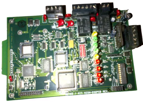
Product Installation Document
This document covers the procedures and specifications for installing the above listed unit and when appropriate, information regarding configuration on the monitored device. For more detailed configuration and operation information, refer to Network Installation Manual, Echelon Local Area Server Manual, or BCI 3 Manual as appropriate.
Description of the Serial NION-232B
The Serial NION-232B (Network Input Output Node) is the EIA-232 interface used with the network. All of the system components are based on Lon Works (Local Operating Network) technologies. The Serial NION-232B provides transparent or interpreted communications between the workstation and control panels. Unless otherwise noted, full control capabilities are available for each interface. Check specific connections for details.
The NION connects a Lon Works FT-10 or FO-10 network, and the RS-232 port of control panels. It provides a single, two-way communication channel for RS-232 serial data when connected to a control panel. NIONs are specific to the type of network to which they connect (FT-10 or FO-10). The transceiver type must be specified and ordered separately when ordering the NION.
The NION can be powered by any 24VDC power limited source with battery backup which is UL listed for use with fire protective signaling units.
The NION mounts in an enclosure (ADT-NIS CAB-1 or CHS-4L in ADT-CAB-3 series enclosure) with conduit knockout
Site Requirements
The NION-232B can be installed in the following environmental conditions:
- Temperature range of 0ºC to 49ºC (32°F – 120°F).
- 93% humidity non-condensing at 30ºC (86°F).
Mounting
The NION-232B is designed to be installed on a wall within 20 feet of the control panel in the same room. The type of hardware used is at the discretion of the installer, but must be in accordance with local code requirements.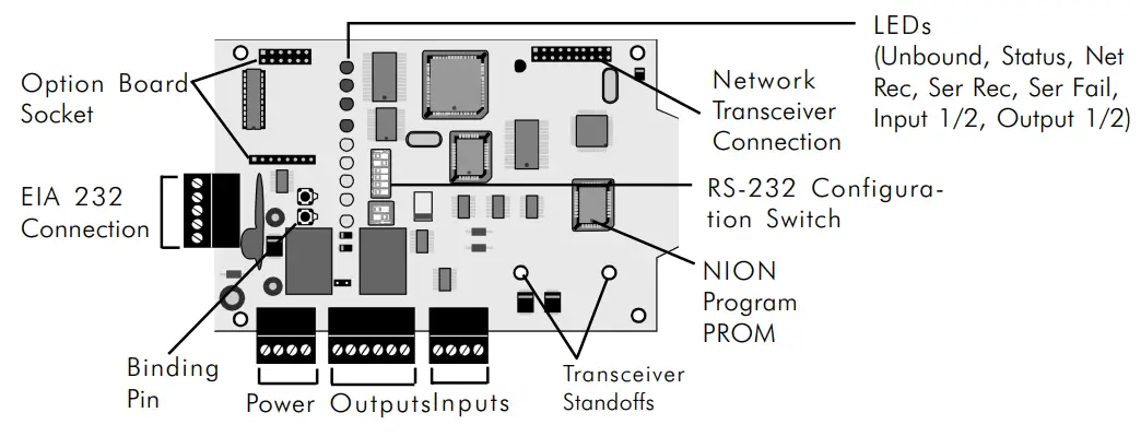
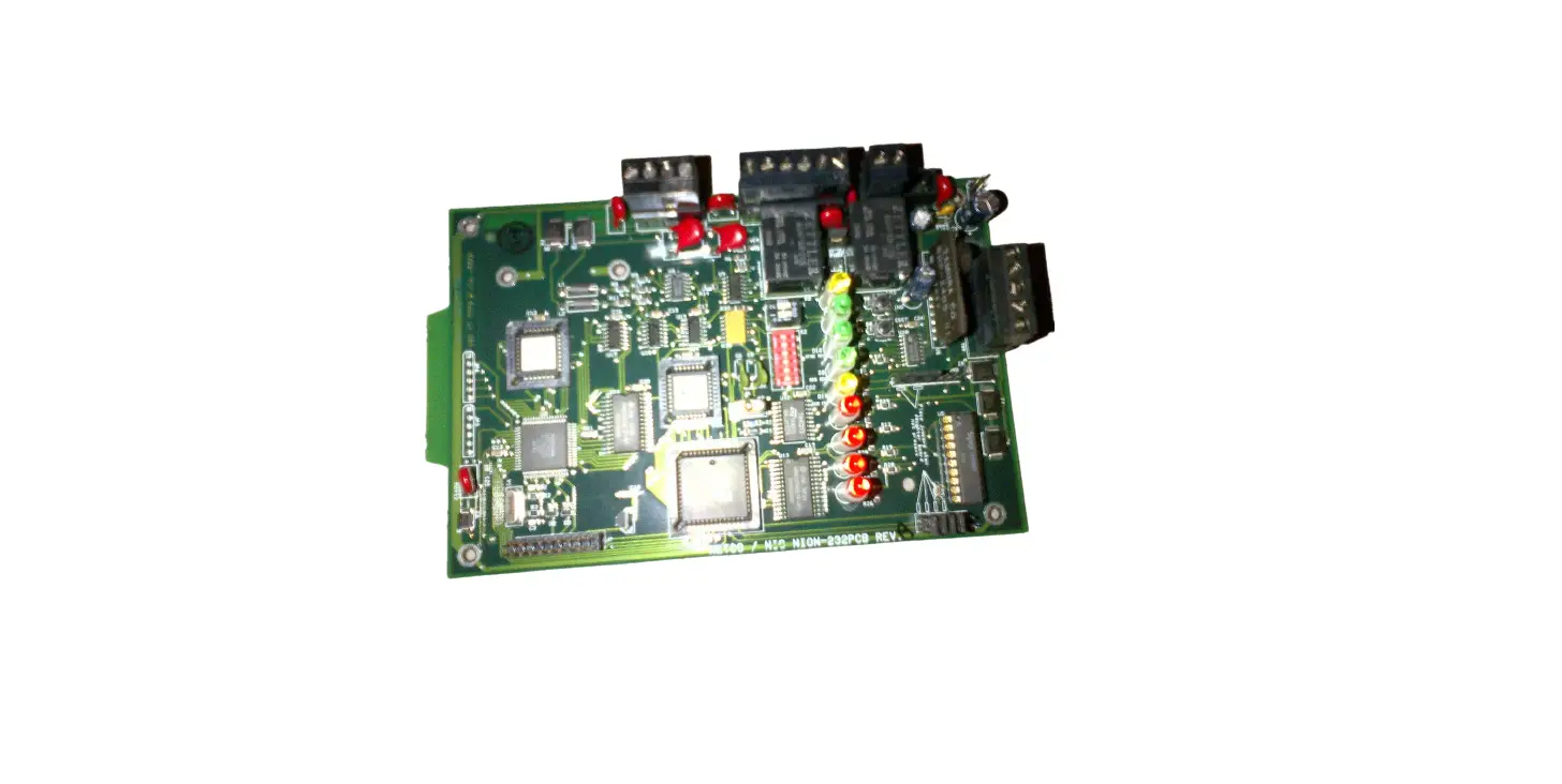
NION-PCB (General)
Serial Communication Description
The baud rate, parity and data bits of the NION-232B must be equal to those of the RS-232 serial port of the control panel. The NION-232B comes from the factory preset for the application it was ordered to fill. These settings are made on switch S2.
If it becomes necessary to change any of these settings use the chart below:
| Baud Rate | Switch Position 4 | Switch Position 5 | Switch Position 6 |
| 600 | Off | On | On |
| 1200 | On | Off | On |
| 2400 | Off | Off | On |
| 4800 | On | On | Off |
| 9600 | Off | On | Off |
| ParityNone Odd Even | Switch Position 2On On Off | Switch Position 3On Off Off | |
| Data Bits | Switch Position 1 | ||
| 8 | On | ||
| 7 | Off |
![]() NOTE: If the device connected to the NION calls for 9 data bits then the NION must be set to 8 data bits with either Even or Odd parity.
NOTE: If the device connected to the NION calls for 9 data bits then the NION must be set to 8 data bits with either Even or Odd parity.
Switch S2 Settings for the NION-232B RS-232 Configuration
NION Power Requirements
The NION-232B requires 24 VDC @ 0.080 A nominal and battery backup in accordance with local coderequirements. It can be powered by any power limited source with battery backup which is UL listed for use with fire protective signaling units.
Serial Communications with the MNNA
The RS-232 settings for the MNNA panel are:
Baud Rate – 2400, Data Bits – 7, Stop Bits – 1, Parity – Even.
![]() NOTES: It is recommended that the installer conform to local code requirements when installing all wiring . All power connections must be non-resettable. Refer to the current Notifier catalog for specific part numbers and ordering information for each NION. Always remove power from the NION before making any changes to switch settings and removing or installing option modules, SMX network modules and software upgrade chips or damage may result. Always observe ESD protection procedures.
NOTES: It is recommended that the installer conform to local code requirements when installing all wiring . All power connections must be non-resettable. Refer to the current Notifier catalog for specific part numbers and ordering information for each NION. Always remove power from the NION before making any changes to switch settings and removing or installing option modules, SMX network modules and software upgrade chips or damage may result. Always observe ESD protection procedures.
Serial Connections with the MultiNet Network Annunciator (MNNA)
The NION-MNNA must be connected to the control/display panel of the INA. Serial communication wires must be connected to the TB2 connector (EIA 232). For specific connections, refer to Figure: NION-MNNA/MNNA Wiring Diagram. The NION should be mounted within 20ft of the panel with all connections run in conduit.
Powering the NION from the MNNA Panel
The NION should use terminals 2 (+24) and 4 (Common) of the TB3 connector on the control/display panel to get auxiliary power from the MNNA. This power source is power limited and non-resettable. For specific connections, refer to Figure: NION-MNNA/MNNA Wiring Diagram.
Configuring the MNNA Panel
Be sure that terminal supervision and printer monitoring are disabled. This is done in Partial System Programming (PSYS) – External Equipment Parameters (EXTEQ).
![]() NOTE: On-line sessions are not available through the MNNA
NOTE: On-line sessions are not available through the MNNA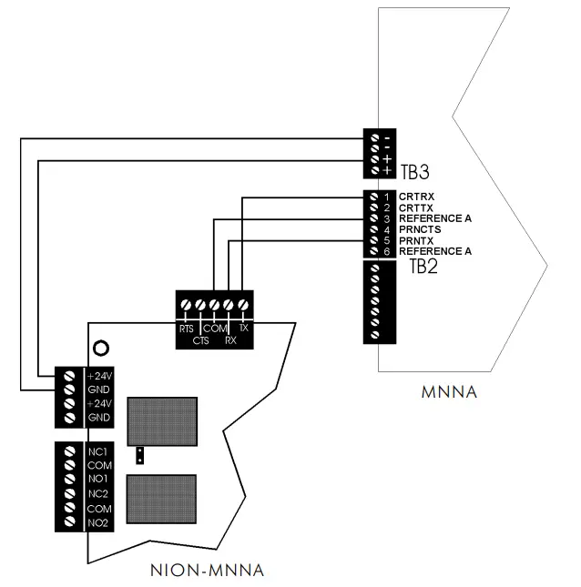
NION-MNNA/MNNA Wiring Diagram
![]() NOTE: Use only wire for power limited systems. Power limited wire runs use type FPLR, FPLP, FPL or equivalent cabling per NEC 760.
NOTE: Use only wire for power limited systems. Power limited wire runs use type FPLR, FPLP, FPL or equivalent cabling per NEC 760.


