![]()
Proudly working in partnership with![]()
![]()
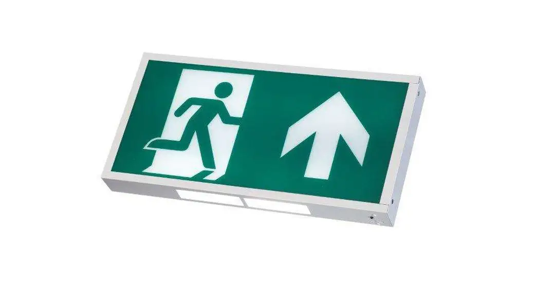
FXBX LED EMERGENCY EXIT BOX
Thank you for purchasing our FXBX LED Emergency Exit Box.
Our products have been designed according to the relevant standards and if installed and maintained correctly they will provide a long service life.
BS EN 60598-1 / BS EN 60598-2-22 / BS EN 50172 / BS EN 1838 / BS EN 62034 / ISO 7010 / ISO 3864
Installation, Maintenance, and Servicing Notes
- Ensure that the mains supply is switched off before installing, maintaining, or servicing the luminaire.
- Luminaires should only be installed by qualified personnel.
- The LED light source and control gear are non-replaceable. Once end-of-life is reached, the luminaire should be replaced.
- In case of mains supply failure, the battery will automatically energize the emergency light for a minimum 3hr period. After 3hrs 5m the luminaire will enter standby mode to protect the battery from over-discharge. The battery must be recharged within 6 months of a full discharge.
- Self-test emergency luminaires are programmed to carry out functional and full duration tests according to BS EN 50172:2004.
- The first battery charge will take up to 16hrs.
- Battery recharge takes up to 8hrs. Note that the full cycle (discharge and recharge) takes up to 12hrs.
- Contact Fox Lux if a battery replacement is required.
- Warranty terms apply. See website for details.
Testing Options
| Standard | Testing and commissioning must be carried out manually according to BS EN 50172:2004. |
| Self-test | A functional test is carried out automatically once a week and runs for the 30s. Full duration test is carried out automatically every 52 weeks. The first full-duration test is carried out automatically within the first 4 weeks after the luminaire is connected to mains. This luminaire can be used with the optional Remote Control (REM10) which adds extra features to Fox Lux emergency luminaires. Please refer to the REM10 user guide . |
LED Status Indications
| GREEN LED | RED LED | Green | Red | STATUS | ACTION REQUIRED |
| Solid ON | OFF | OK | |||
| Normal Flash | OFF | Charging | |||
| OFF | Solid ON | Battery disconnected / Duration test failure | Connect battery / Replace battery | ||
| Fast Flash | OFF | Functional/Duration test in progress | |||
| Normal Flash | Normal Flash | Battery temperature | Contact Fox Lux | ||
| OFF | Normal Flash | Light source fault | Replace luminaire | ||
![]() Normal flash = 1Hz (once/second)
Normal flash = 1Hz (once/second)![]() Fast flash = 2Hz (twice/second)
Fast flash = 2Hz (twice/second)
![]()
 Ensure this product is disposed of responsibly according to WEEE directive 2002/96/EC
FXBX LED Exit Box
FXBX Exit Box Range
| Reference | Description | Testing | Remote | Operating temp. ta | Net weight |
| FXBX/M/3 | Emergency Exit Box 3hr Maintained (standard) | Manual | control | 0°C – 40°C | 1.15kg |
| FXBX-S/M/3 | Emergency Exit Box 3hr Maintained (self-test) | Self-test | REM10* | 0.14kg | |
| FXBX-D | DOWN ARROW legend panel | ||||
| FXBX-R | The RIGHT ARROW legend panel | ||||
| FXBX-L | The LEFT ARROW legend panel | ||||
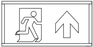
| FXBX-U | UP ARROW legend panel |
*Remote Control REM10 allows the competent user to carry out functional tests and/or full duration tests at any time and to check system status. Please refer to the REM10 user guide.
Installation Guide
1: Isolate mains supply
Ensure that the mains supply is switched off before installing, maintaining, or servicing the emergency luminaire.
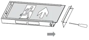
2: Remove side panel and legend
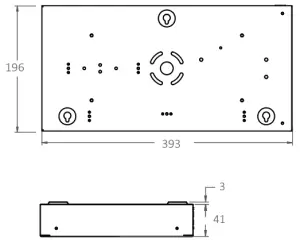
3: Body installation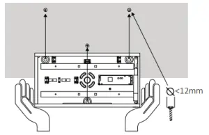
Drill where indicated and use wall plugs+screws*
Remove knock-out on the side or top if connected to 20mm conduit *supplied screws and rawl plugs are suitable for masonry only. Please purchase alternative fixings if required.
4: Electrical connection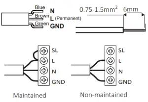
5: Restraint of cables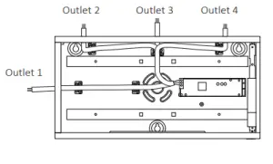
Secure mains cable by using cable clip and screws or the grommet supplied in the box.
6: Integrated downlight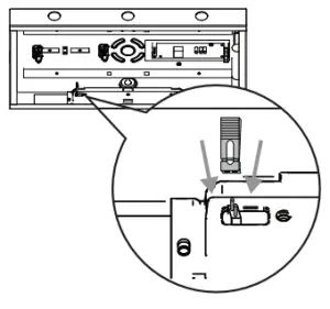
If downlight is not required, remove the jumper to disconnect
7: Complete labels 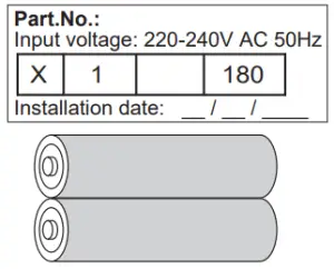
– Enter installation date on battery label
– Enter the appropriate code on the luminaire label
8: Refit legend and side panel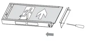
9: Restore mains supply
NET LED Limited | 300 Anderson Road | Buckingway Business Park | Cambridge | CB24 4UQ Tel: 01223 851505 Email: [email protected]
Our T&C‘s are available online


