
AL-KO BC 225 L, BC 225 B Garden + Hobby Instruction Manual
Introduction
Read this documentation before starting up the machine. This is a precondition for safe working and flawless operation.
- Observe the safety warnings in this documentation and on the machine.
- This documentation is a permanent integral part of the product described
- and must be passed on to the new owner if the machine is sold.
Explanation of symbols
![]() Caution!
Caution!
Following these safety warnings carefully can prevent personal injury and/or material damage.
![]() Special instructions for greater ease of understanding and improved handling.
Special instructions for greater ease of understanding and improved handling.
Meaning of symbols on the machine
 Caution!
 Read the instruction manual
- Wear safety goggles, safety helmet, ear defenders
- Wear gloves
 Wear safety shoes
 Only operate the equipment with cutting strings.
- Danger due to ejected objects
- The distance between the device and other persons must be at least 15 m.
- BC 225 L: Blades not permitted!
Intended use
This device is intended for trimming and mowing lawns on private premises.
Using this device for any other or additional purpose is considered contrary to its intended use.
![]() Caution!
Caution!
The device must not be used commercially.
Safety instructions
- The machine may only be used in perfect technical condition.
- Only work when there is adequate daylight or artificial lighting
- The machine must not be operated with different cutting tools or attachments.
- Wear appropriate working clothes:
- Long trousers, sturdy footwear, gloves
- Safety helmet, safety goggles, ear defenders
- Always ensure stability when working.
- The machine must not be operated if the operator is under the influence of alcohol, drugs or medication.
- Always operate the machine with both hands.
- Keep the handles dry and clean.
- Keep body and clothing away from cutting parts.
- Keep third parties away from the danger area.
- Remove foreign bodies from the working area.
- Always keep the guard, string head and engine free of mowing debris
- When leaving the machine:
- Switch off the engine.
- Wait until the cutting parts have come to a standstill.
- Do not leave the machine unattended.
- Never allow children or untrained persons to operate or service the machine. There may be local regulations regarding minimum age requirements for operating the machine.
- Accident prevention regulations must be observed.
- The user is responsible for accidents involving other persons and their property
![]() Caution!
Caution!
During extended periods of use the vibrations can cause disorders of the blood vessels or nervous systems of the fingers, hands and wrists. You may experience parts of your body going numb, twinges, pains or changes in the skin. If such symptoms arise, please consult your doctor!
Safety and protective equipment
![]() Caution!
Caution!
Safety and protective equipment must not be disabled – Risk of injury!
Emergency Stop
In the event of an emergency, swith the ignition switch to “STOP”.
Stone impact guard
Protects the operator from ejected objects. The integrated cutter shortens the cutting string to the permissible length.
Specification
| BC 225 L | BC 225 B | |
| Motor type | Air-cooled 2-stroke engine | Air-cooled 2-stroke engine |
| Cylinder capacity | 25 cm3 | 25 cm3 |
| Power | 0,7 kW | 0,7 kW |
| Dry weight (EN ISO 11806) | 7,1 kg | 5,5 kg |
| Sound power level ISO 22868 | 113 dB(A) K = 3,0 dB (A) | 109 dB(A) K = 3,0 dB (A) |
| Sound pressure level ISO 22868 | 98,5 dB(A) | 105,5 dB(A) |
| Vibration ISO 22867 | 6,2 m/s2 K=1,5 m/s2 | 3 m/s2 K=1,5 mist |
| Cutting string width | 41 cm | 41 cm |
| Cutting string diameter | 2 mm | 2.4 mm |
| Cutting width, cutting blade | – | 25 cm |
| Grip | L-handle | “Bike” grip |
| Ignition | Electronic | Electronic |
| Spark plug | L8RTC | L8RTC |
| Drive train | Centrifugal clutch | Centrifugal clutch |
| Max. engine speed | 10,000 r.p.m. | 10,000 r.p.m. |
| Engine idle speed | 2,800 r.p.m. | 2,800 r.p.m. |
| Tool speed | 7,000 r.p.m. | 7,000 r.p.m. |
BC 225 L assembly
Parts overview (Fig. 1)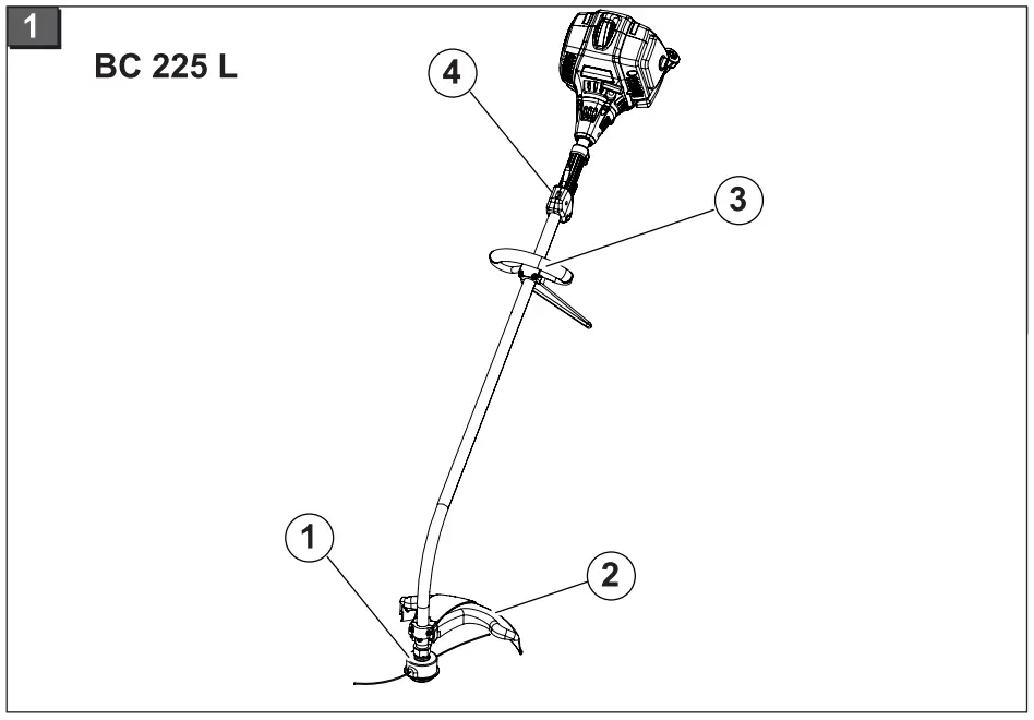
- String head
- Driver
- Guard
- Bike“ grip
- Lever, see Starting the engine
![]() Caution!
Caution!
The machine must not be operated before assembly work has been completed.
Mounting the L grip (BC 225 L) (Fig. 2)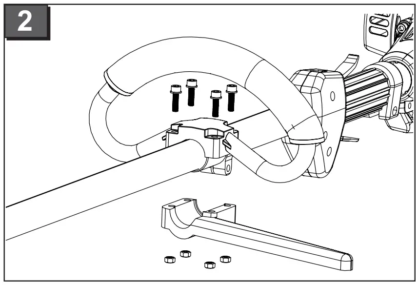
- Place the rubber sleeve over the support bar.
- Screw together the lower half of the grip and the top half above the rubber sleeve using the four Allen screws.
Mounting the guard (BC 225 L) (Fig. 3)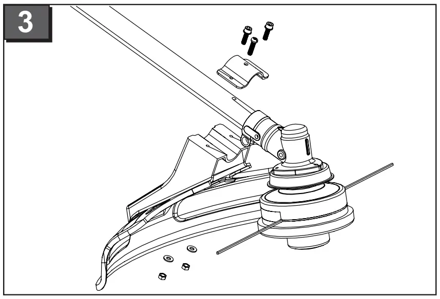
- Fix cover and mounting sleeve with the center hexagon socket screw on the stem and tighten.
- Screw protection cover with the remaining two hexagon socket screws
Mounting the string head (BC 225 L) (Fig. 4)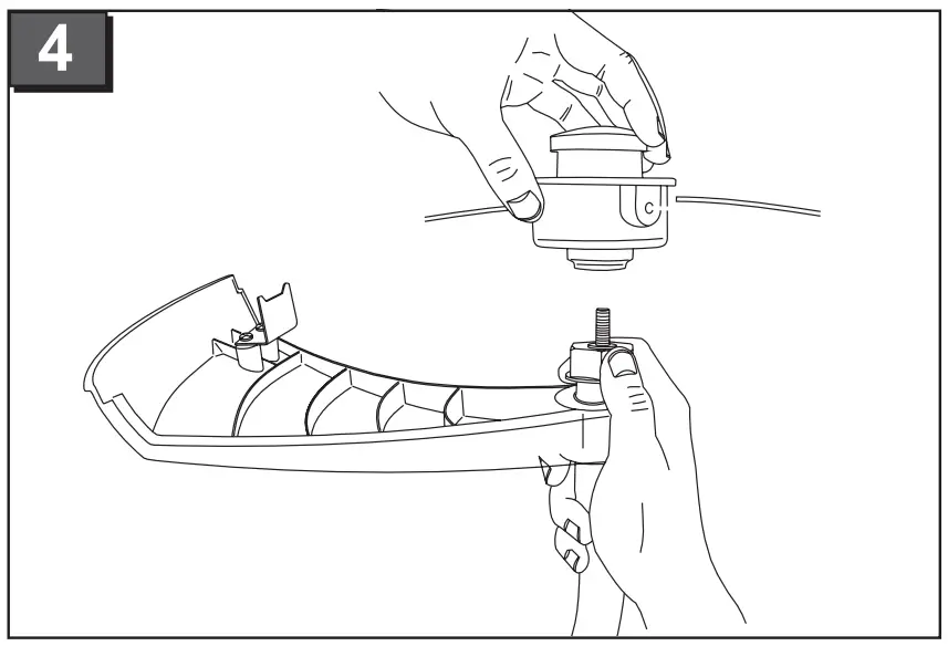
- Hold the driver disc with your hand.
- Screw the string head onto the guide pin.
Caution: Left-hand thread.
BC 225 B assembly
Parts overview (Fig. 1)
- String head
- Drive shaft
- Guard
- “Bike” grip
- Lever, see Starting the engine
![]() Caution!
Caution!
The machine must not be operated before assembly work has been completed.
“Bike” grip (Fig. 2) (Fig. 3)
- Place the rubber sleeve over the support bar.
- Screw together the lower brace and the grip holder over the rubber sleeve using the four Allen screws.
- Place the grip rod into the grip holder.
- Fasten the upper brace onto the grip holder using the four Allen screws.
Mounting the cutting blade (Fig. 5)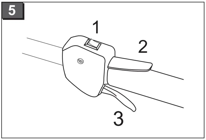
- Place the drive plate onto the guide pin on the drive shaft.
- Place the cutting blade onto the drive plate so that the hole in the cutting blade is positioned precisely on the guide circle on the drive plate.
- Push the flange onto the cutting blade so that the flat side faces the cutting blade.
- Fit the fan washer.
- Secure the clamping nut onto the guide pin. To do this, insert the Allen key into the relevant holes and tighten using the spark plug wrench provided. Caution: left-hand thread!
- Secure the nut with the cotter pin.
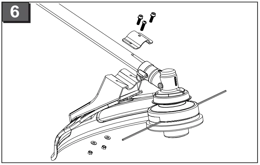
Mounting the guard (Fig. 6)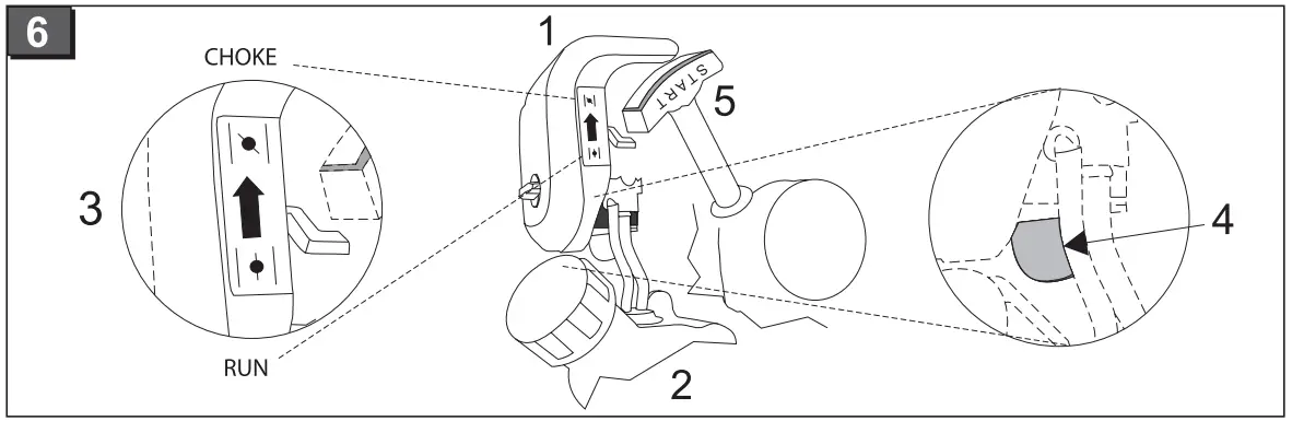
- Fix protection cap with medium screw on the handlebar.
- Protective cover with the remaining two hex screws and hex nuts tighten.
Mounting the string head (Fig. 7)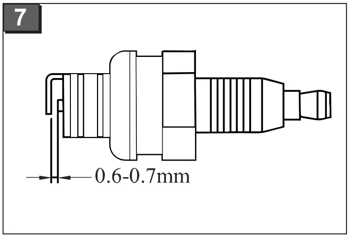
- Place the drive plate onto the guide pin on the drive shaft.
- To lock, insert the Allen key into the hole in the driver disc.
- Screw the string head onto the guide pin.
Caution: left-hand thread!
Adjusting the shoulder strap (Fig. 1)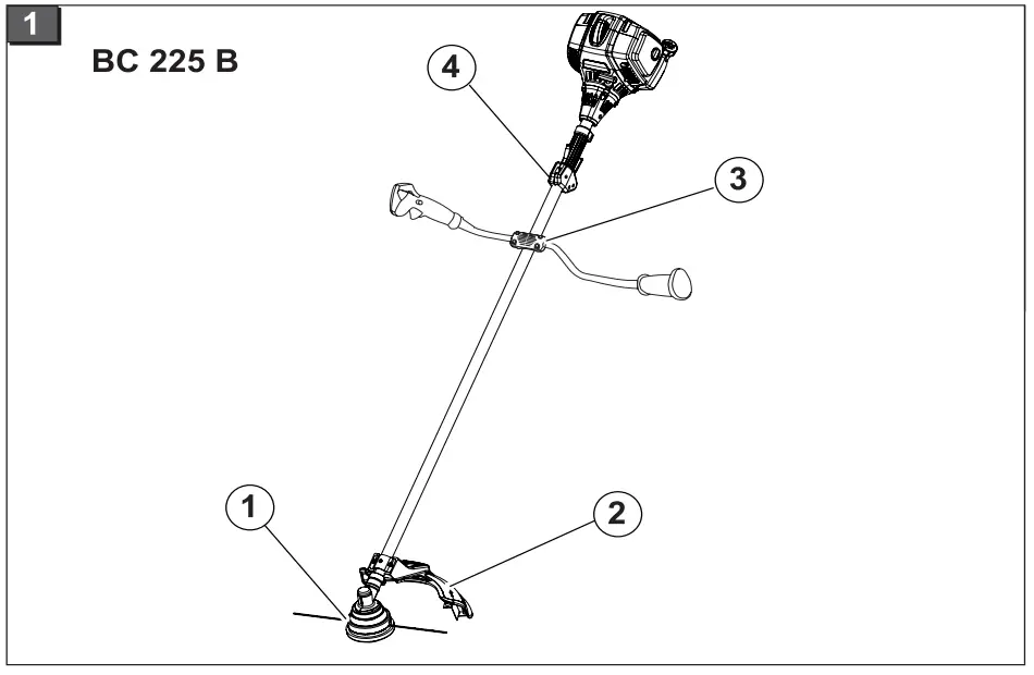
- Push the shoulder strap over your left shoulder.
- Hook the locking hooks into the eyelet (1-6).
- Check the length of the shoulder strap by making a number of swinging movements without switching on the engine.
The string head or cutting blade must move parallel to the ground.
![]() Caution!
Caution!
Always use the shoulder strap when working with the device.
Only hook up the shoulder strap once the engine is started and idling.
Fuel and consumables
Safety instructions
![]() Warning!
Warning!
Petrol is highly flammable – Fire hazard!
- Ensure that no fuel leaks from the engine, tank or fuel lines.
- Only mix and store petrol in approved containers.
- Do not use any fuel mixture that has been stored for more than 90 days.
- Only refuel outdoors.
- Do not smoke while refuelling.
- Do not open the fuel cap while the engine is running or hot.
- Exchange the tank or fuel cap if damaged.
- Always keep the fuel cap firmly closed.
- Only empty the fuel tank outdoors.
- If petrol has spilled out:
- Do not start the engine.
- Avoid ignition attempts.
- Clean the machine.
- Allow leftover fuel to evaporate
Preparing a fuel mixture
![]() Only use fuel in a ratio of 25:1.
Only use fuel in a ratio of 25:1.
- Pour petrol and a branded 2-stroke oil into a suitable container in accordance with the table.
- Mix both parts thoroughly.
Table of fuel mixing ratios
Mixing procedure | Petrol | Mixing oil |
| 25 parts petrol: | 1 l | 40 m |
| 1 part mixing oil | 3 l | 120 ml |
| 2-stroke mixing oil | 3 l | 200 ml |
Starting the BC 225 L and BC 225 B
![]() Caution!
Caution!
Always carry out a visual inspection before starting up the machine.
- Before use, ensure that all screws, nuts and bolts on the device are securely fastened
- The machine must not be operated with loose, damaged or worn cutting equipment and/or fixing components
- Replace damaged or worn parts with genuine spare parts.
- Always operate the trimmer with the guard.
- Always observe the operating instructions provided by the manufacturer of the engine.
- Observe local regulations regarding operating times.
Starting the engine
![]() Warning!
Warning!
Never run the engine indoors. Toxic fumes!
![]() Before start-up, shorten the cutting string to 13 cm to avoid overloading the engine.
Before start-up, shorten the cutting string to 13 cm to avoid overloading the engine.
Choke settings:![]()
Note the following for a cold start of the BC 225 L and BC 225 B:
- Place the strimmer flat on the ground away from any other objects.
- Ensure that the cutting tool is not in contact with any objects or the ground.
- Ensure that it is stable.
- Hold the device with your left hand. With your right hand, grip the starter cord.
- Do not stand or kneel on the support.
- Always pull the starter cord straight out. Never allow it to snap back abruptly.
Starting the BC 225 L
BC 225 L cold start (Fig. 5) (Fig. 6)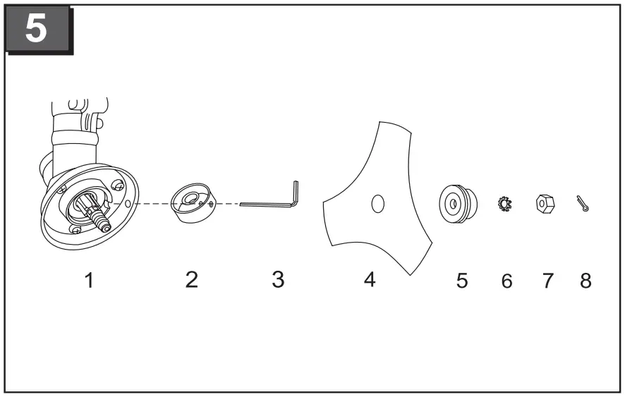
| 5-1 | „Start“ – „Stop“ ignition |
| 5-2 | Throttle lock |
| 5-3 | Gas lever |
| 6-1 | Air filter shroud |
| 6-2 | Petrol tank |
| 6-3 | Choke“ – „Run“ ignition flap |
| 6-4 | Primer (cold-start diaphragm pump) |
| 6-5 | Starter cord |
- Set the ignition switch to the “Start” position.
- Press and hold the throttle lock, press the throttle.
- Set the choke to the “CHOKE” position.
- Press the cold start membrane pump 10 times.
- Pull out the starter cord 3 or 4 times until the engine starts up (ignites) audibly for a brief time. Pull the cord briskly with uniform force.
- Once the engine has started: set the choke to “RUN”.
- Pull out the starter cord until the engine starts.
- If the engine does not start, repeat steps 1 to 7.
BC 225 L warm start (Fig. 5) (Fig. 6)
- Set the ignition switch to the “Start” position.
- Set the choke to „RUN“. Pull the starter cord – the engine will start.
- Engine does not start:
- Set the choke to the “RUN” position.
- Pull the starter cord 5 times.
- If the engine still does not start:
- Wait 5 minutes and then try again with the gas lever pressed down.
Switch off the engine (Fig. 5)
- Release the gas lever and let the engine idle.
- Set the ignition switch to “STOP”.
![]() Caution!
Caution!
The engine and cutting parts will continue to run-on after switching off – risk of injury!
Starting the BC 225 B
BC 225 B cold start (Fig. 8) (Fig. 9)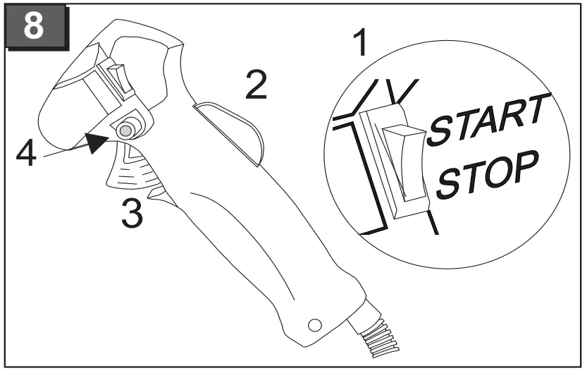

| 8-1 | „Start“ – „Stop“ ignition |
| 8-2 | „Lock-Off“ switch |
| 8-3 | Throttle lock |
| 8-4 | Gas lever |
| 9-1 | Air filter shroud |
| 9-2 | Petrol tank |
| 9-3 | „Choke“ – „Run“ ignition flap |
| 9-4 | Primer (cold-start diaphragm pump) |
| 9-5 | Starter cord |
- Set the ignition switch to the “Start” position.
- Lock the gas lever:
- Press and hold the throttle lock
- Press and hold the throttle
- Press and hold the „Lock off“ switch
- Release the throttle The throttle runs at full throttle.
- Release the „Lock off“ switch.
- Set the choke to the “CHOKE” position.
- Press the cold start membrane pump 10 times.
- Pull out the starter cord 2 or 3 times until the engine starts (ignites) audibly for a brief time. Pull the cord briskly with uniform force.
- Once the engine has started: set the choke to “RUN”.
- Pull out the starter cord until the engine starts.
- If the engine does not start, repeat steps 1 to 7.
BC 225 B warm-start (Fig. 8) (Fig. 9)
- Set the ignition switch to the “Start” position.
- Set the choke to the „RUN“ position.
- Pull the starter cord quickly a maximum of 6 times – the engine will start. Keep the gas lever pressed down fully until the engine runs smoothly.
- Engine does not start:
- Set the choke to the “RUN” position.
- Pull the starter cord 5 times.
- If the engine still does not start:
- Wait 5 minutes and then try again with the gas lever pressed down.
Switching off the BC 225 B engine (Fig. 8)
- Engine does not start:
- Release the throttle and allow the engine to idle.
- Switch the ignition to „STOP“.
![]() Caution!
Caution!
The engine and cutting tools continue to run on after being switched off – risk of injury.
Instructions for use
Always let the engine run in the upper speed range during trimming and cutting.
Safety instructions
![]() Caution!
Caution!
Observe the safety warnings in this documentation and on the machine.
- Persons who are not familiar with the trimmer should practise handling it with the engine switched off
- Wear appropriate working clothes
- Always ensure stability when working.
- Always operate the machine with both hands.
- Keep body and clothing away from cutting parts.
- Keep third parties away from the danger area.
- Never hold the string head higher than knee level when the device is in operation.
- Do not spray the unit with water and protect against rain and humidity.
- When mowing on sloping ground, always stand downhill of the cutting device.
- Never work on a slippery hillside or slope.
- Never use the device in the vicinity of highly flammable liquids or gases – Risk of fire and/or explosion!
- After contact with a foreign object:
- Switch off the engine.
- Examine the device for damage
Lengthening the cutting string
- Let the engine run at full throttle and tap the string head on the ground.
The cutting string will be extended automatically. The blade on the safety shield shortens the cutting string to the permissible length.
Cleaning the guard
- Switch off the device.
- Carefully remove mowing debris with a screwdriver or similar tool.
![]() Clean the guard regularly to prevent the shaft tube from overheating.
Clean the guard regularly to prevent the shaft tube from overheating.
Trimming
- Examine the terrain and determine the desired cutting height.
- Guide and hold the string head at the desired height.
- Swing the device from side to side in a sweeping, scythe-like motion.
- Always keep the string head parallel with the ground.
Close trimming
- Hold the device so that it is tilted forward at a slight angle and moves just above the ground.
- Always trim away from your body.
Trimming along fences and foundations
![]() Caution!
Caution!
Do not come into contact with solid structures – Danger of recoil!
- Move the unit slowly and carefully without allowing the cutting string to hit any obstacles.
Trimming around tree trunks
- Guide the device slowly and carefully around tree trunks, ensuring that the cutting string does not touch the tree bark.
- Mow from left to right around tree trunks.
- Cut grass and weeds with the tip of the string and keep the string head tilted slightly forwards.
![]() Trimming along stone walls, foundations and tree leads to increased string wear.
Trimming along stone walls, foundations and tree leads to increased string wear.
Mowing
- Tilt the string head to the right at an angle of 30 degrees.
- Move the handgrip to the desired position.
![]() Caution!
Caution!
Remove foreign objects from the working area. Risk of injury / damage to property from ejected foreign objects.
Mowing with the cutting blade
When mowing with the cutting blade, the cutting blade should be guided in a curving horizontal motion from one side to the other.
![]() Caution!
Caution!
Before using the cutting blade, observe the following additional instructions:
- Use the shoulder strap.
- Check the safety hood and cutting blade for correct installation.
- Wear protective clothing and eye protection.
![]() Do not use weed cutter blades for cutting brushwood and young trees!
Do not use weed cutter blades for cutting brushwood and young trees!
![]() Caution!
Caution!
Only use original cutting knives and accessories!
Non-original parts can cause injuries and device malfunctions!
Avoiding recoil
![]() Caution!
Caution!
Danger of recoil / risk of injury!
Do not use the cutting blade in the vicinity of fixed obstacles –
Never use blunt cutters and avoid uncontrolled contact with foreign bodies. Otherwise there will be an increased risk of the equipment kickback, which could throw the machine around. As a result the operator could be make involuntary movements, which could lead to serious injuries.
Jamming
Dense vegetation, young trees or brushwood can jam the cutting blade and stop it turning.
- Avoid jamming by noting the direction in which the vegetation leans and then cutting from the opposite side.
- If the cutting blade becomes entangled during cutting:
- Switch off the engine immediately.
- Hold up the device so that the cutting blade does not jump or break.
- Push the caught material away
Maintenance and care
- Clean the device after every use with a brush and a dry cloth. Do not use cleaning agents or water.
Air filter
![]() Caution!
Caution!
Never operate the device without an air filter. Clean the air filter regularly. Exchange the filter if damaged.
- Remove the star screw, take off the cover and take out the air filter.
- Clean the air filter with soap and water. Do not use petrol!
- Allow the air filter to dry.
- Install the air filter in reverse sequence.
Fuel filter Caution!
Never operate the device without a fuel filter. Severe engine damage may result. - Completely remove the fuel cap.
- Empty the remaining fuel into a suitable container.
- Pull the filter out of the tank with a wire hook.
- Remove the filter with a twisting motion.
- Exchange the filter
Carburettor adjustment
The carburettor is optimally adjusted at the factory.Spark plug (BC 225 L, Fig. 7) (BC 225 B, Fig. 4)
Spark plug gap = 0.635 mm [0.025”]. - Tighten the spark plug with a torque of 12-15 Nm.
- Push the spark plug connector onto the spark plug.
Sharpening the string cutter blade
- Remove the cutting blade from the guard.
- Clamp the cutting blade in a vice and sharpen it with a flat file. File in one direction only
Storage
- Empty the fuel tank before long periods of storage (over the winter)
- Only empty the fuel tank outdoors
- Allow the engine to cool down before storage
- Empty the fuel tank.
- Start the engine and let it idle until it stops.
- Let the engine cool down.
- Loosen the spark plug with a spark plug socket.
- Pour a teaspoon of 2-stroke oil into the combustion chamber. Pull the starter cord slowly several times to distribute the oil in the interior of the engine.
- Insert the spark plug again.
- Thoroughly clean and service the device.
- Store the device in a cool dry place.
![]() Caution!
Caution!
Do not store the machine in the vicinity of naked flames or heat sources – Risk of fire and/or explosion!
![]() Caution! Fire hazard!
Caution! Fire hazard!
Do not store fuelled machine in buildings where the petrol fumes might come into contact with naked flames or sparks!
Keep the area around the engine, exhaust, battery case and fuel tank clear of grass cuttings, petrol and oil.
Recommissioning
- Remove the spark plug.
- Quickly pull the starter cord to remove leftover oil from the combustion chamber.
- Clean the spark plug, check the electrode distance.
- Re-install the spark plug, replace if necessary.
- Prepare the device for operation.
- Fill the tank with the correct fuel/oil mixture (25:1).
Troubleshooting
Problem | Correction |
| Engine does not start | Incorrect starting procedure, observe the operating instructions. Clean the spark plug and the air and fuel filters. |
| Engine starts but does not continue to run | Set the lever to RUN. Clean / adjust or replace the spark plug. Clean or exchange the filter. |
| Engine starts but does not run with full performance | Set the lever to RUN. Clean or exchange the filter. |
| Motor runs spasmodically | Clean / adjust or replace the spark plug. |
| Excessive smoke | Use the correct fuel mixture (ratio 25:1). |
Faults that cannot be corrected with the help of this table must be rectified in an authorized, specialist workshop.
Disposal
Machines that are no longer required must not be disposed of with household waste!
Packaging, machine and accessories are manufactured using recyclable materials and must be disposed of accordingly.
EC DECLARATION OF CONFORMITTY
We hereby declare that this product, in the form in which it is marketed, meets the requirements of the harmonised EU guidelines, EU safety standards, and the product-specific standards..
Product: Trimmer
Serial number: G2302305
Model: BC 225 L BC 225 B
Sound power level measured / guaranteed
EN ISO 3744
BC 225 L 98 / 113 dB(A)
BC 225 B 105 / 109 dB(A)
Manufacturer
AL-KO Geräte GmbH Ichenhauser Str. 14 89359 KOETZ
DEUTSCHLAND
EU directives
- 2006/42/EG
- 2004/108/EG
- 2000/14/EG
- 2002/88/EG
Conformity evaluation
- 2000 /14/EG
- Anhang V
Executive Officer
Andreas Hedrich Ichenhauser Str. 14 89359 KOETZ DEUTSCHLAND
Harmonised standards
- EN ISO 11806
- EN ISO 14982
- EN ISO 22867
- EN ISO 22868
Notified body
TÜV Rheinland Product Safety
GmbH Am Grauen Stein 51105 Köln Germany
Kötz, 2014-12-15
Wolfgang Hergeth, Managing Director
Warranty
If any material or manufacturing defects are found during the statutory customer protection period, we will either repair or replace the equipment, whichever we consider the more appropriate. This statutory period may vary according to the legislation in force in the country where the equipment was purchased.
Our warranty is valid only if:
- The equipment has been used properly
- The operating instructions have been followed
- Genuine replacement parts have been used
The warranty is no longer valid if:
- The equipment has been tampered with
- Technical modifications have been made
- The equipment was not used for its intended purpose (for example, used for commercial or communal applications)
The following are not covered by warranty:
- Paint damage due to normal wear
- Wear parts identified by a border XXX XXX (X) on the spare parts list
- Combustion motors – these are covered by a separate warranty from the manufacturer concerned
To make a claim under warranty, please take this statement of warranty and proof of purchase to the nearest authorised customer service centre. This warranty does not affect the usual statutory rights of the customer relative to the seller.
Support
AL-KO Geraete GmbH l Head Quarter l Ichenhauser Str. 14 l 89359 Koetz l Deutschland 10_2014
Telefon: (+49)8221/203-0 l
Telefax: (+49)8221/97-8199 l
www.al-ko.com


