![]()
![]() Manual
Manual
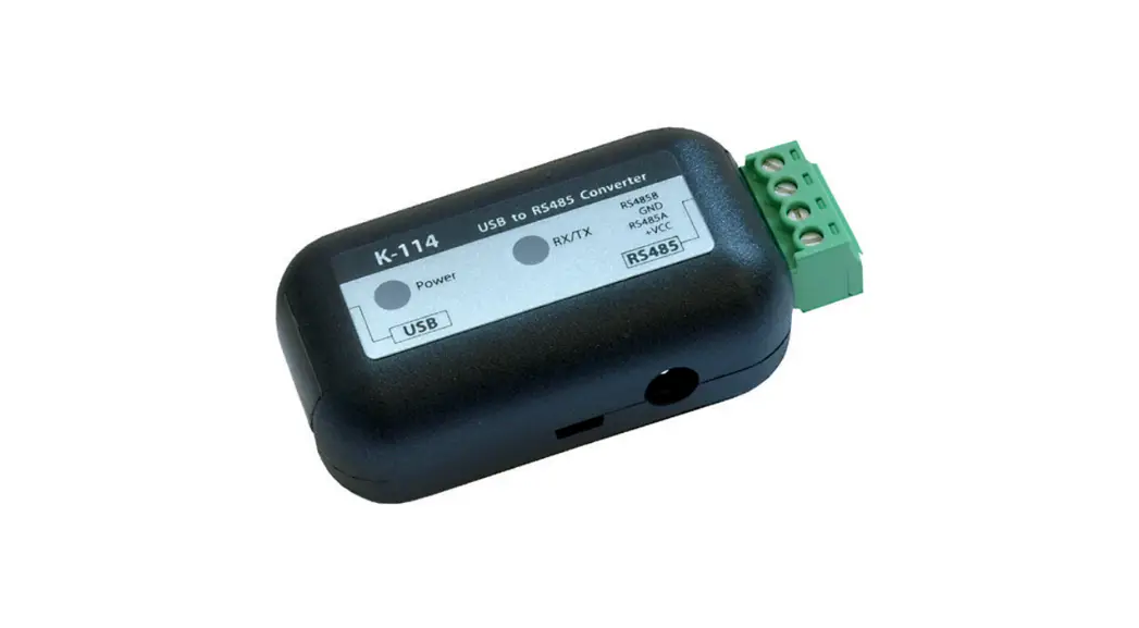
Interface Converter K-114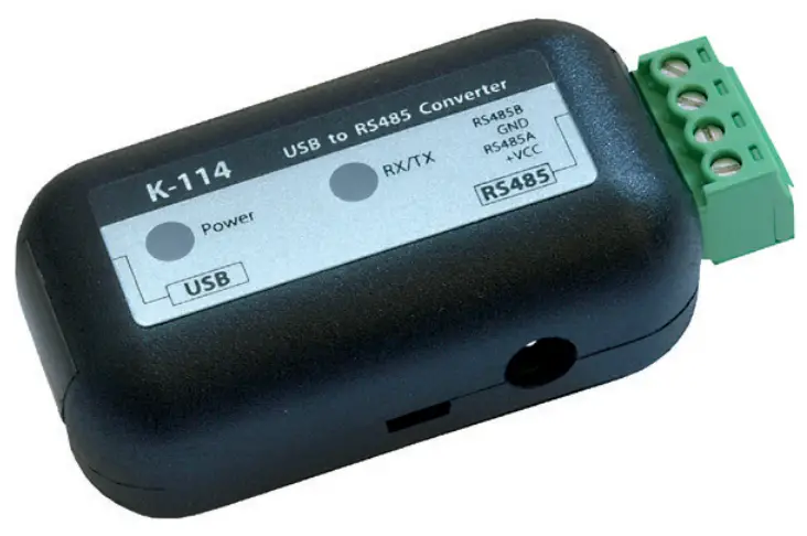
K-114 Interface Converter
General information
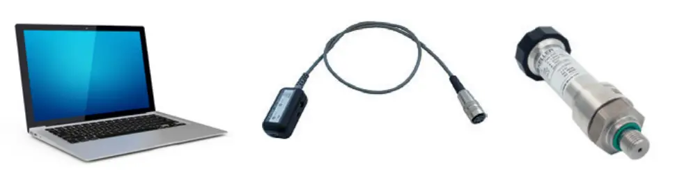
The K-114 interface converter is used to convert a USB signal to a serial RS485 half-duplex signal, for connection to any desired computer with a USB port. The K-114 converter and the connected transmitters are powered via the USB connection. An external power supply unit can also be connected to power multiple instruments. The K-114 converter is preferred for use with KELLER products.
With the K-114 interface converter, you can… convert a USB signal to RS 485 (half-duplex) measure the applied signal voltage (0…12 VDC) e.g. the output signal voltage from a pressure transmitter measure the power consumption of connected end consumers in the 0…40mA range e.g. the power consumption of connected end consumers or the power output signal from a pressure transmitter The K-114 interface converter offers you visual status and configuration displays (LED) electrical isolation between the computer and the converter diagnostic tools
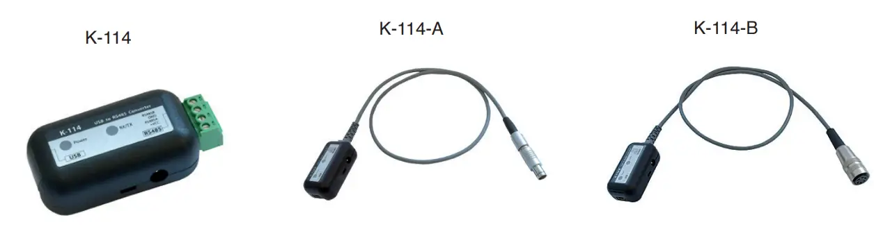
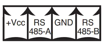
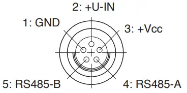
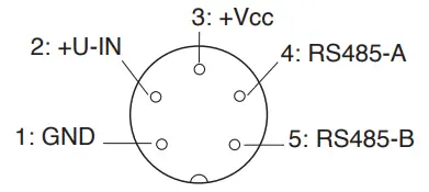
Pin assignment for converter / connections
| K-114 plug-in screw terminal | K-114-A Fischer plug-in connector S 103 A054-130 | K-114-B Binder female cable connector Serie 680 5-pole |
 |  |  |
Technical specifications
| Symbol | Parameter | Condition | Min. | typ. | Max. | Unit |
| Current consumption, K-114 | No connection | 30 | 43 | 55 | mA | |
| Power consumption, K-114 | No connection | 150 | 215 | 275 | mW | |
| Supply for end consumer(s) | U-Out | No power supply unit | 11,2 | 12. | 12,5 | VDC |
| Supply for end consumer(s) | I-Out | With power supply unit | – | 150 | mA | |
| External supply | Power supply unit | 12 | 15 | 20 | VDC | |
| Input voltage | U-In | K-114-A / K-114-B | 0 | 12 | VDC | |
| Accuracy of input voltage | U-In | R! >- 30 k() | 0,2 | 0,3 | %FS | |
| Current measurement | I-Out | 0 | 40 | mA | ||
| Accuracy of current measurement | I-Out | 0,2 | 0,3 | %FS | ||
| Data transmission rate | slow | Max. transmission distance 20 km | – | – | 250 | kbps |
| high | Max. transmission distance 1 km | – | 3 | Mbps | ||
| K-114 device | Protection Class | IP40 | – | – | – | |
| Device fuse (USB) | Fl | No power supply unit | 0,5 | A | ||
| Storage and operating temperatures | -10 | 20 | 50 | °C |
Description
The K-114 communicates with the connected devices via an RS485 (half-duplex mode) bus. The devices connected to the K-114 are supplied via the PC’s USB output or via an external power supply unit (K-114 socket). KELLER products operate with fail-safe drivers that generate a logical «high» at the reception output in case of short-circuited, open or terminated inputs, in order to avoid invalid signal statuses. KELLER products also have a slew rate limitation which limits the edge steepness (i.e. slew rate) of the driver output. This prevents high-frequency emissions from devices and data lines. Up to a maximum of 128 transmitters can be connected to this RS485 master bus.
Typical application
Overview of products
| Product | Connection | Product number | Products supported |
| K-114 | Plug-in screw terminal | 309010. | All digital KELLER products Series 3X, Series 4X, DCX* |
| K-114A | Fischer plug | 309010. | DCX-16 /-22-25PVDF / -38, LEO-Record, LEX1, ARC1 |
| K-114B | Binder female cable connector | 309010. | Series 30X / 40X, LEO3, EV-120, dV22-PP, dV2-PS**, Castello** |
| K-114M | M12 female cable connector | 309010. | DCX-18 only (communication and charging cable) |
* no voltage input
** requires additional cable option
System requirements for K-114_Config software
| Processor | min. Pentium 75 MHz |
| Screen resolution | min. 1024 x 768 |
| Main (working) memory | min. 16 MB RAM |
| Free hard disk space | min. 20 MB (recommended) |
| Internet connection | recommended (required for support) |
| Operating system | Windows XP Windows 7 |
Factory configuration for the K-114
| Converter bus address | 253 (cannot be changed) |
| Baud rate | 9600 baud |
| Echo off | off |
| Bias network | off |
| Termination High Speed | off |
| High Speed | off |
These settings are generally recommended to ensure troublefree operation of KELLER products.
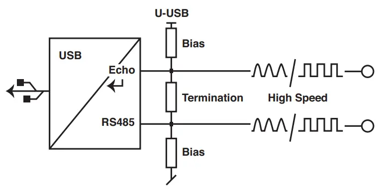
Functional overview for the K-114
Echo off
Data sent from the PC (TX) aren’t received by the PC.
Bias network
Prevents undefined bus levels when line drivers are inactive.
➞ Greater immunity to interference
Termination
Prevents reflections on the signal lines.
High Speed
Disables the RS485 driver’s slew-rate limitation.
This allows communication at higher transmission speeds (> 250 kbps). Unlike high speed mode, the standard mode (< 250 kbps) reduces reflections on the signal lines and provides better EMC behaviour.
KELLER devices operate at transmission speeds < 250 kbps, so this function is not activated ex factory.
LED display
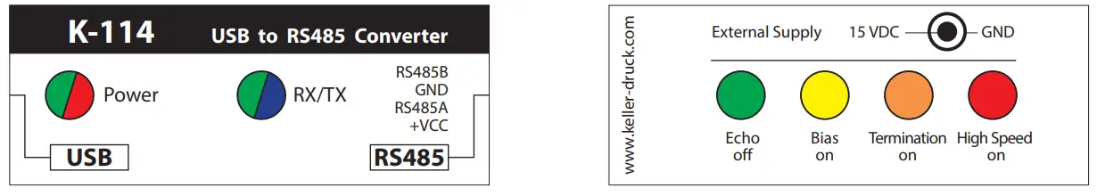
Power
![]() Ready to operate
Ready to operate![]() Flashing rapidly, error ➞ U-USB < 4,5 VDC ➞ Connect power supply unit
Flashing rapidly, error ➞ U-USB < 4,5 VDC ➞ Connect power supply unit![]() Flashing slowly, error ➞ U-UOUT < 11,2 VDC ➞ Connect power supply unit
Flashing slowly, error ➞ U-UOUT < 11,2 VDC ➞ Connect power supply unit![]() Error
Error
RX/TX
Shows the status of the transmission line (TX) and the reception line (RX).![]() TX, sending data via the RS485 bus
TX, sending data via the RS485 bus![]() RX, receiving data via the RS485 bus
RX, receiving data via the RS485 bus
Echo off
Shows the status of the Echo off function.![]() Echo off disabled (➞ echo switched on)
Echo off disabled (➞ echo switched on)![]() Echo off enabled (➞ echo switched off)
Echo off enabled (➞ echo switched off)
Bias on
Shows the status of the Bias on function.**![]() Bias resistors (560 Ω) for RS485A and B are enabled
Bias resistors (560 Ω) for RS485A and B are enabled![]() No bias resistors are connected
No bias resistors are connected
KELLER products use fail-safe RS485 drivers which output a valid signal even with an undefined level.
For this reason, it is not mandatory to enable this function.
Termination on![]() Termination resistor (120 Ω) connected**
Termination resistor (120 Ω) connected**![]() Termination resistor not connected
Termination resistor not connected
High Speed
Shows the status of the High speed function.**![]() High speed enabled
High speed enabled![]() High speed disabled
High speed disabled
**IMPORTANT: On battery-powered devices, this function can lead to operating errors ➞ Recommendation: do not enable the function.
RoHS![]() This product is compliant with EC directive 2002/95/EC on the Restriction of the Use of Certain Hazardous Substances in Electrical and Electronic Equipment (RoHS).
This product is compliant with EC directive 2002/95/EC on the Restriction of the Use of Certain Hazardous Substances in Electrical and Electronic Equipment (RoHS).
Disposal![]() This symbol on the product or the product documentation indicates that the product must not be disposed of as normal household waste at the end of its useful life. In order to prevent potential damage to the environment or to health as a result of uncontrolled waste disposal, this product must be separated from other waste and must be correctly recycled in order to ensure the sustainable use of the raw materials.
This symbol on the product or the product documentation indicates that the product must not be disposed of as normal household waste at the end of its useful life. In order to prevent potential damage to the environment or to health as a result of uncontrolled waste disposal, this product must be separated from other waste and must be correctly recycled in order to ensure the sustainable use of the raw materials.
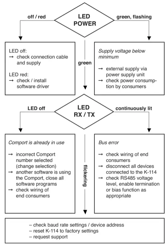
Help with fault analysis
Installing the K-114_Config software
First, install the K-104 / K-114 driver on your computer and then run the K-114_Config software.
(The software can be downloaded free of charge at www.keller-druck.com)
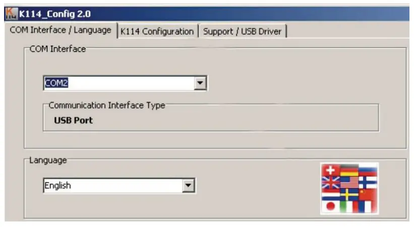
Running the K-114_Config software
Run K-114_Config and select the appropriate COM port. Then go to the K-114 Configuration view (top right).
Tip: When the program is open, Comport is selected automatically as soon as the K-114 is plugged into the computer.
Voltage and current measurements with K-114_Config
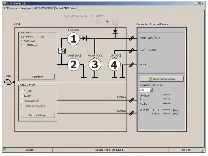
| No. | Symbol | Function | Description |
| 1 | I-OUT | Current supply — external consumer | No valid display during operation with external current supply |
| 2 | U-USB | USB voltage supply | |
| 3 | U-OUT | Voltage supply — external consumer | Switched-in voltage supply is indicated via U-OUT |
| 4 | U-IN | Voltage input | Range: 0…12 VDC |
Warnings and other messages in the software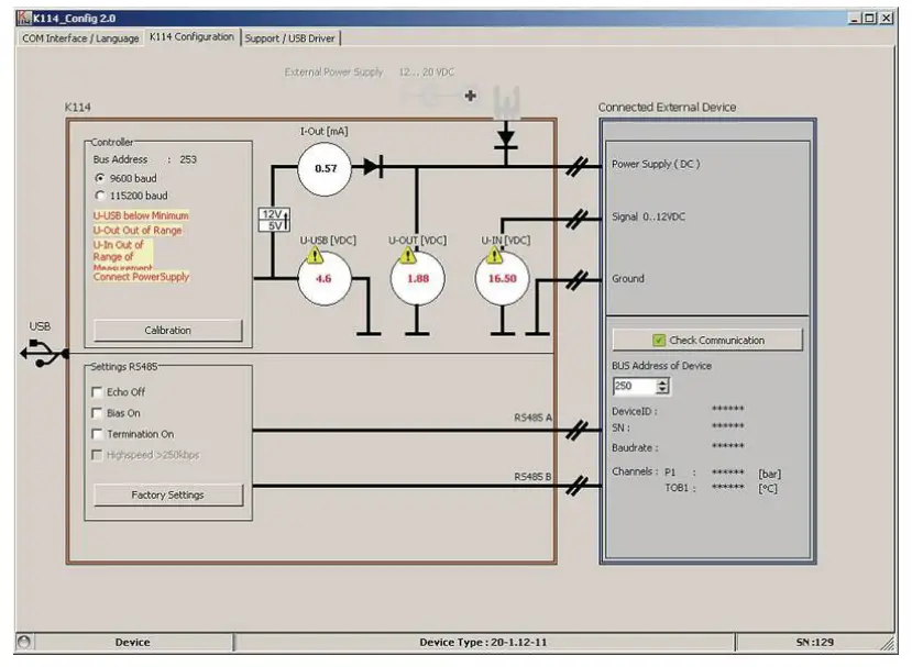
U-USB is below minimum
This message appears if the U-USB voltage is below 4,8 VDC. Fault-free functioning of the converter is no longer guaranteed. Supply the converter from an external power supply unit.
U-OUT outside of range
This message appears if U-OUT is less than 11,2 VDC. Supply the converter from an external power supply unit.
U-IN outside of measurement range
The U-IN measurement range is from 0…12 VDC. The exclamation mark warns you that the upper limit of the measuring range that can be displayed (> 16 VDC) has been reached.
The voltage for measurement that is actually applied (U-IN) can therefore be greater than the value for U-IN that is displayed.
Connect power supply unit
If the difference between U-OUT and U-IN is less than 3 VDC, the «Connect power supply unit» message appears.
Getting support
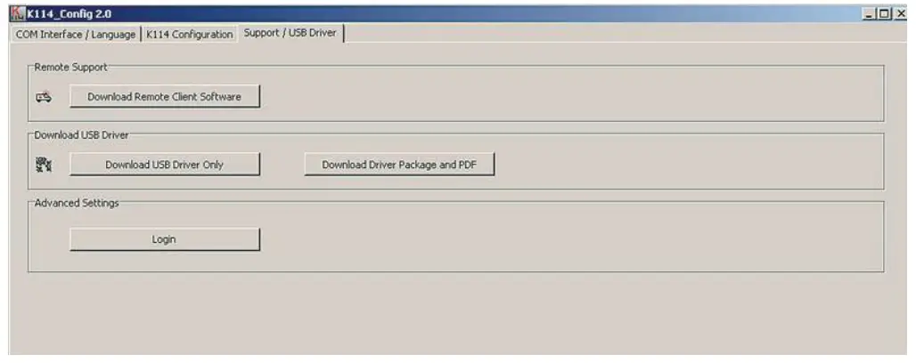
If faults or errors occur while you are working with the converter, use the Help with fault analysis section to rectify the problem. If problems persist after you have worked through this section, you can request assistance from KELLER by telephone. For contacts, visit: www.keller-druck.com
The «Download remote maintenance software» function automatically launches the download of a Remote Desktop Program. Once the download has completed, run the program. After you enter the connection code, our technical support team will log into your computer and offer you on-the-spot help directly on your screen.
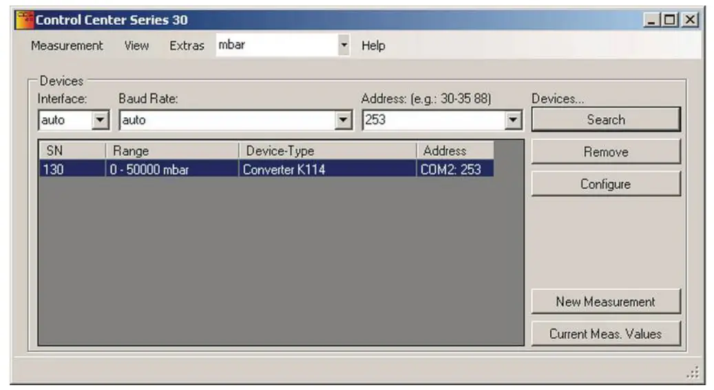
Recording K-114 measurement data
The values measured for I-OUT, U-IN, U-OUT and U-USB can be recorded and saved via Software ControlCenterSeries30 (CCS30). (Read the CCS30 manual on this subject.)
To view the K-114 controller’s measured values via the software, you must enter bus address 253 in the CCS30 and let the device search. Use the «New measurement» function key to view and save the measurement data.
Declaration of Conformity
Herewith we declare, that the following product Converter K-114 meet the basic requirements, which are established in the guidelines of the European Community Directive EMC 2014/30/EU Directive RoHS 2011/65/EG under following conditions
- Cable lengths of less than 3 m
- For use inside buildings
As criteria, the following norms for this converter are applied.
EN 61326-1:2013 EN 61000-6-2:2011 EN 61000-6-4:2011
This declaration is given for the manufacturer:
St. Gallerstrasse 119, CH-8404 Winterthur in full responsibility by
KELLER GmbH, Schwarzenegger 17, DE-79798 Jeannette
March
![]() Managing Owen with legally effective signature
Managing Owen with legally effective signature
KELLER AG für Druckmesstechnik
CH-8404 Winterthur![]() +41 52 235 25 25
+41 52 235 25 25![]() [email protected]
[email protected]
KELLER Ges. für Druckmesstechnik mbH
DE-79798 Jestetten![]() +49 7745 9214 0
+49 7745 9214 0![]() [email protected]
[email protected]
Version | Edition
12/2022![]() www.keller-druck.com
www.keller-druck.com


