
SONBEST XJ102L PM10 Temperature and Humidity Integrated Sensor
XJ102L using the standard LORA Wireless Communication Interface,easy access to PLC,DCS and other instruments or systems for monitoring temperature,humidity,CO2,PM2.5,PM10 state quantities.The internal use of high-precision sensing core and related devices to ensure high reliability and excellent long-term stability,can be customized
RS232,RS485,CAN,4-20mA,DC0~5V\10V,ZIGBEE,Lora,WIFI,GPRS and other output methods.
Technical Parameters
| Technical parameter | Parameter value |
| Brand | XUNHOME |
| Temperature measuring range | -30℃~80℃ |
| Temperature measuring accuracy | ±0.5℃ @25℃ |
| Humidity measuring range | 0~100%RH |
| Humidity accuracy | ±3%RH @25℃ |
| PM2.5 range | 0~999ug/m3 |
| PM2.5 accuracy | ±15% or ±10ug/m3 max @25℃ |
| PM10 range | 0~999ug/m3 |
| PM10 accuracy | ±15% or ±35ug/m3 max @25℃ |
| Maximum transmit power | MAX 20dBm |
| Operating frequency | 410-441MHz Default 434MHz |
| Work mode | query mode or active upload mode |
| Communication Protocol | MODBUS-RTU Protocol |
| Sleep battery | <8uA |
| Max Current | <150mA |
| Sleep interval | 1-36000 seconds |
| Built-in battery | lithium battery inside |
| Standby duration | 2 to 5 years (collected every 30 minutes) |
| Power | DC6~24V 1A |
| Running temperature | -40~80°C |
| Working humidity | 5%RH~90%RH |
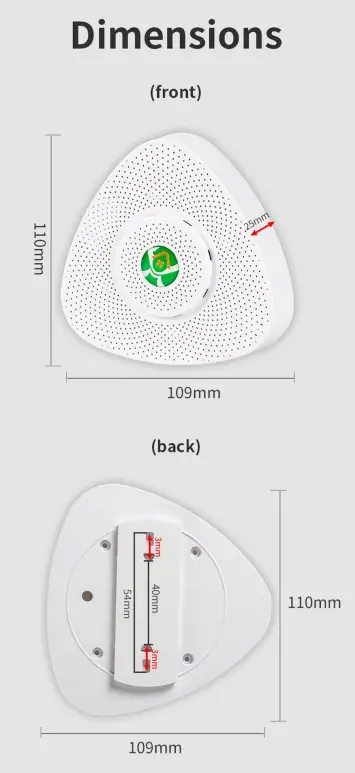
Dimensions
System Frame Diagram
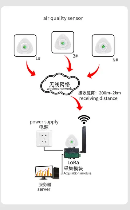
Scope Of Use

Communication Protocol
Because the device only has LORA wireless communication mode, the user can read and modify the parameters involved in this communication protocol through the wireless transparent transmission of the LORA transparent transmission module. The product uses the MODBUS-RTU standard protocol format, All operation or reply commands are hexadecimal data. The default device address is 1 when the device is shipped from the factory. The default baud rate is 9600, 8, n, 1. Since the LORA sensor cannot directly modify the LORA parameters, it is generally based on the standard parameters (434MHz). The carrier frequency, that is, channel 24) is shipped. If other parameters such as channel, signal bandwidth, and spreading factor are required, please specify when ordering.
Read Data (Function id 0x03)
Inquiry frame (hexadecimal), sending example: Query 1# device 1 data, the host computer sends the command:01 03 00 00 00 05 85 C9 .
| Device ID | Function id | Start Address | Data Length | CRC16 |
| 01 | 03 | 00 00 | 00 05 | 85 C9 |
For the correct query frame, the device will respond with data:01 03 0A 00 79 00 7A 00 7B 00 7C 00 7D 15 10 , the response format is parsed as follows:
| Device ID | Function id | Data Length | data 1 | data 2 | data 3 | data 4 | data 5 | Check Code |
| 01 | 03 | 0A | 00 79 | 00 7A | 00 7B | 00 7C | 00 7D | 15 10 |
Data Description: The data in the command is hexadecimal. Take data 1 as an example. 00 79 is converted to a decimal value of 121. If the data magnification is 100, the actual value is 121/100=1.21. Others and so on.
Data Address Table
| Address | Start Address | Description | Data type | Value range |
| 40001 | 00 01 | temperature | read | 0~65535 |
| 40002 | 00 02 | humidity | read | 0~65535 |
| 40003 | 00 03 | CO2 | read | 0~65535 |
| 40004 | 00 04 | PM2.5 | read | 0~65535 |
| 40005 | 00 05 | PM10 | read | 0~65535 |
| 40101 | 00 64 | model code | read/write | 0~65535 |
| 40102 | 00 65 | total points | read/write | 1~20 |
| 40103 | 00 66 | Device ID | read/write | 1~249 |
| 40104 | 00 67 | baud rate | read/write | 0~6 |
| 40105 | 00 68 | mode | read/write | 1~4 |
| 40106 | 00 69 | protocol | read/write | 1~10 |
| 40107 | 00 6A | interval | read/write | 0~36000 |
| 40108 | 00 6B | channel | read/write | 0~31 |
| 40109 | 00 6C | transmit power | read | 0~3 |
| 40110 | 00 6D | signal bandwidth | read | 0~9 |
| 40111 | 00 6E | spreading factor | read | 0~6 |
LoRa has a total of 32 channels. When the device is concentrated, you can change the channel to prevent signal crosstalk. The default channel value is 24, which corresponds to 434MHz. The device generates from 410MHz to 441MHz every 1MHz. For example, if the current channel value is 24, the actual frequency of use is: 410+24=434MHz.
Device transmit power is divided into 4 files, 0 pairs are 20db, 1 pair is 17db, 2 pairs are 14db, 3 pairs are 11db, because the actual transmit power is related to many factors, so here is the maximum transmit power .
Signal bandwidth is divided into 10 files,read only, default 07, ie 125KHz, 0-9 are: 7.8KHz, 10.4KHz, 15.6KHz, 20.8KHz, 31.2KHz, 41.7KHz, 62.5KHz, 125KHz, 250KHz ,500KHz.
the spreading factor value range is 0 to 6,read only, the default is 02, ie SFactor=8, 0-6 corresponds to the spreading factor SFactor: 6, 7, 8, 9, 10, 11, 12, respectively.
Read and modify device address
- Read or query device address
If you don’t know the current device address and there is only one device on the bus, you can use the command FA 03 00 64 00 02 90 5F Query device address.Device ID Function id Start Address Data Length CRC16 FA 03 00 64 00 02 90 5F FA is 250 for the general address. When you don’t know the address, you can use 250 to get the real device address, 00 64 is the device model register.
For the correct query command, the device will respond, for example the response data is: 01 03 02 07 12 3A 79, the format of which is as shown in the following table:Device ID Function id Start Address Model Code CRC16 01 03 02 55 3C 00 01 3A 79 Response should be in the data, the first byte 01 indicates that the real address of the current device is, 55 3C converted to decimal 20182 indicates that the current device main model is 21820, the last two bytes 00 01 Indicates that the device has a status quantity.
- Change device address
For example, if the current device address is 1, we want to change to 02, the command is:01 06 00 66 00 02 E8 14 .Device ID Function id Start Address Destination CRC16 01 06 00 66 00 02 E8 14 After the change is successful, the device will return information: 02 06 00 66 00 02 E8 27 , its format is parsed as shown in the following table:
Device ID Function id Start Address Destination CRC16 01 06 00 66 00 02 E8 27 Response should be in the data, after the modification is successful, the first byte is the new device address. After the general device address is changed, it will take effect immediately. At this time, the user needs to change the query command of the software at the same time.
Read and Modify Baud Rate
- Read baud rate
The device default factory baud rate is 9600. If you need to change it, you can change it according to the following table and the corresponding communication protocol. For example, read the current device’s baud rate ID, the command is:01 03 00 67 00 01 35 D5 , its format is parsed as follows.Device ID Function id Start Address Data Length CRC16 01 03 00 67 00 01 35 D5 Read the baud rate encoding of the current device. Baud rate encoding: 1 is 2400; 2 is 4800; 3 is 9600; 4 is 19200; 5 is 38400; 6 is 115200.
For the correct query command, the device will respond, for example the response data is: 01 03 02 00 03 F8 45, the format of which is as shown in the following table:Device ID Function id Data Length Rate ID CRC16 01 03 02 00 03 F8 45 coded according to baud rate, 03 is 9600, ie the current device has a baud rate of 9600.
- Change the baud rate
For example, changing the baud rate from 9600 to 38400, ie changing the code from 3 to 5, the command is: 01 06 00 67 00 05 F8 1601 03 00 66 00 01 64 15 .Device ID Function id Start Address Target Baud Rate CRC16 01 03 00 66 00 01 64 15 Change the baud rate from 9600 to 38400, changing the code from 3 to 5. The new baud rate will take effect immediately, at which point the device will lose its response and the baud rate of the device should be queried accordingly. Modified
Read Correction Value
- Read Correction Value
When there is an error between the data and the reference standard, we can reduce the display error by adjusting the correction value. The correction difference can be modified to be plus or minus 1000, that is, the value range is 0-1000 or 64535 -65535. For example, when the display value is too small, we can correct it by adding 100. The command is: 01 03 00 6B 00 01 F5 D6 . In the command 100 is hex 0x64 If you need to reduce, you can set a negative value, such as -100, corresponding to the hexadecimal value of FF 9C, which is calculated as 100-65535=65435, and then converted to hexadecimal to 0x FF 9C. The correction value starts from 00 6B. We take the first parameter as an example. The correction value is read and modified in the same way for multiple parameters.Device ID Function id Start Address Data Length CRC16 01 03 00 6B 00 01 F5 D6 For the correct query command, the device will respond, for example the response data is: 01 03 02 00 64 B9 AF, the format of which is as shown in the following table:
Device ID Function id Data Length Data value CRC16 01 03 02 00 64 B9 AF In the response data, the first byte 01 indicates the real address of the current device, and 00 6B is the first state quantity correction value register. If the device has multiple parameters, other parameters operate in this way. The same, the general temperature, humidity have this parameter, the light generally does not have this item.
- Change correction value
For example, the current state quantity is too small, we want to add 1 to its true value, and the current value plus 100 correction operation command is:01 06 00 6B 00 64 F9 FD .Device ID Function id Start Address Destination CRC16 01 06 00 6B 00 64 F9 FD After the operation is successful, the device will return information: 01 06 00 6B 00 64 F9 FD, the parameters take effect immediately after successful change.
Disclaimer
This document provides all information about the product, does not grant any license to intellectual property, does not express or imply, and prohibits any other means of granting any intellectual proper ty rights, such as the statement of sales terms and conditions of this product, other issues. No liability is assumed. Furthermore, our company makes no warranties, express or implied, regarding the sale and use of this product, including the suitability for the specific use of the product, the marketability or the infringement liability for any patent, copyright or other intellectual property rights, etc. Product specifications and product descriptions may be modified at any time without notice.
Contact Us
Brand: XUNHOME
Address: Room 208, Building 8, No. 215, Nandong Road, Baoshan District, Shanghai Xunjia Brand Business Department
Chinese site: http://www.xunhome.net
International site: http://www.xunhome.net
SKYPE: soobuu
E-mail: [email protected]
Tel: 86-021-51083595 / 66862055 / 66862075 / 66861077


