AV Access 4KIP100-KVM 4K IP Based KVM Extender
Introduction
Overview
This product is a 4K IP based KVM Extender. It could extend 4K video (with zero latency) and USB 2.0 signals over long distances, and it is a plug & play product.
Features
- IP based, 1 Gigabit network support 4K video.
- Supports video resolution up to 4K@30Hz. Supports HDCP 1.4.
- Supports 7.1-channels audio.
- Supports EDID limited copy.
- Supports the distance up to 120m (395ft) with Cat 5e/6/6a/7 cable, with network switch, the distance will be extended unlimitedly.
- Supports 3 USB 2.0 for full feature USB 2.0 applications.
- Supports 4-Pin DIP switch for more sets works in a same network, up to 16 sets.
Package Contents
Before you start the installation of the product, please check the package contents:
- Extender x 1
- Power Supply (DC 12 V 1A) x 2
- USB 2.0 Type-B to Type-A Cable (L=1.5m) x 1
- Mounting Brackets (with Mounting Screws) x 4
- User Manual x 1
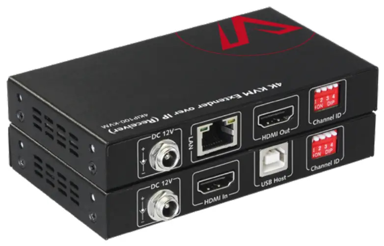
Panel
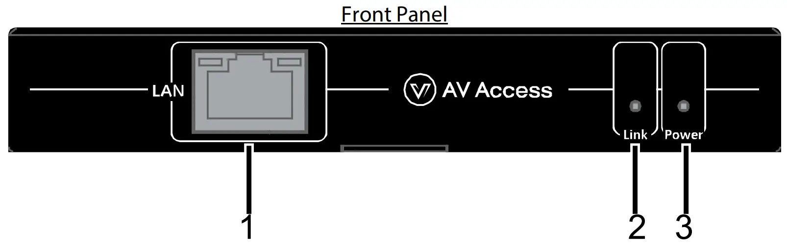
Transmitter
| No. | Name | Description |
| 1 | LAN | Connect to a receiver or an Ethernet Switch for streaming media output. |
| 2 | Link LED | On: The transmitter is paired with the receiver successfully. |
| 3 | Power LED | On: The device is powered on. Off: The device is powered off. |
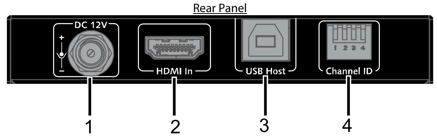
| No. | Name | Description |
| 1 | DC 12V | Connect to the DC 12V 1A power adapter provided. |
| 2 | HDMI In | Connect to HDMI source such as a Blu-ray. |
| 3 | USB Host | Connect a type A male to type B male USB cable between this port and the USB port of a desktop or a laptop. The transmitter is USB 2.0 compliant. |
| 4 | Channel ID | This DIP switch consists of four manual switches, which are used to route the transmitter to receiver based on their positions. For more information, see “Using DIP Switch to Perform Routing”. Note:
|
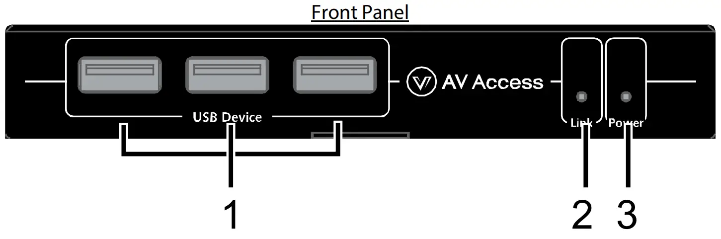
Receiver
| No. | Name | Description |
| 1 | USB Device | Connect to USB devices, e.g., keyboard, mouse and Udisk. |
| 2 | Link LED | On: The receiver is paired with the transmitter successfully. |
| 3 | Power LED | On: The device is powered on. Off: The device is powered off. |
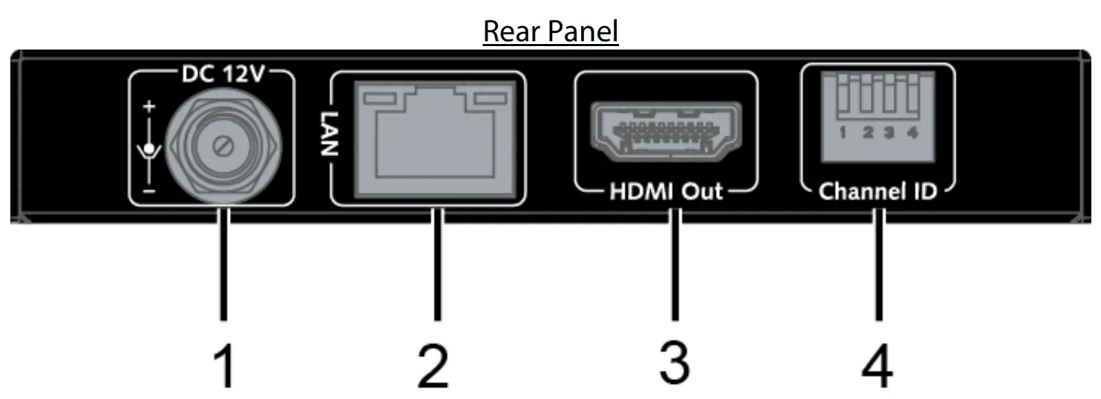
| No. | Name | Description |
| 1 | DC 12V | Connect to the DC 12V 1A power adapter provided. |
| 2 | LAN | Connect to a transmitter or an Ethernet Switch for streaming media input. |
| 3 | HDMI Out | Connect to display such as TV. |
| 4 | Channel ID | This DIP switch consists of four manual switches, which are used to route the transmitter to receiver based on their positions. For more information, see “Using DIP Switch to Perform Routing”. Note:
|
Using DIP Switch to Perform Routing
To route the signal from a transmitter to a receiver, toggle each individual switches of the DIP Switch in receiver to the same positions as these in transmitter. If you want to link the receiver to a different transmitter, change the receiver switch settings in the same way as how the transmitter’s switch is positioned.
Note:
- You must repower the transmitter and receiver for the switch setting changes to take effect
- One transmitter can be only paired with one receiver individually in the same network, i.e., only one set DIP switch of transmitter and receiver can be set to the same position.
Installation and Application
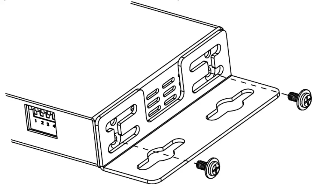
Brackets Installation
Note: Before installation, please ensure 4KIP100-KVM is disconnected from the power source.
- Attach the installation bracket to the enclosure using the screws that were provided in the package separately. The bracket height can be adjusted up/down or bracket face up or down.

- Attach the brackets to the surface you want to hold the unit against using the screws (provided by others).
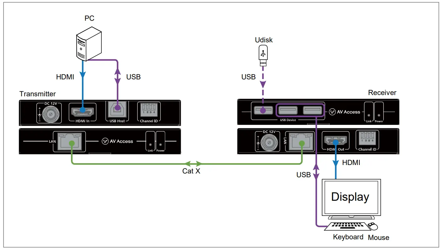
Application
Application 1 – Connect directly
4KIP100-KVM could be connected directly with a Cat 5e or above cable. As a normal extender set, it extends the HDMI and USB signals over a long distance up to 120m/395ft.
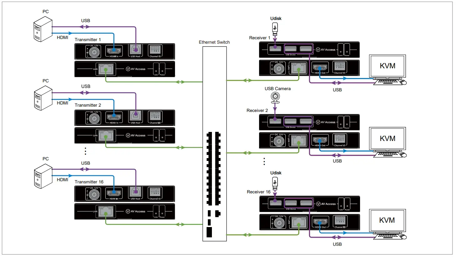
Application 2 – Connect through Ethernet Switch
4KIP100-KVM could be connected through one or more network switches. With the 4-Pin DIP switch, it could connect to 16 extender sets in a same network without the VLAN settings, extend the HDMI and USB signals to an unlimited distance.
Note:
- HDMI cables’ length must be within 15m/49ft.
- One transmitter can be only paired with one receiver individually in the same network, i.e., only one set DIP switch of transmitter and receiver can be set to the same position.
Specification
Transmitter
| Technical | |
| Input/Output | 1 x HDMI IN (19-pin female HDMI Type-A), 1 x USB HOST (female USB Type-B), 1 x 4-Pin DIP Switch, 1 x DC 12V connector with locking, 1 x LAN (RJ45) |
| Input Signal Type | HDMI 1.4b |
| Input Resolution Supported | 640×4808 , 800×6008,10, 1024×7688,10, 1280×7206,7,8,9,10, 1280×7688,10, 1280×8008,10, 1280×9608,10, 1280×10248,10, 1360×7688, 1366×7688 , 1440×9008,10, 1600×9008 , 1600×12008 , 1680×10508,10, 1920×10801,2,3,4,5,6,7,8,9,10, 1920×12008 , 3840x2160P2,3,5, 4096x2160P2,3,51 = at 23.98 Hz, 2 = at 24 Hz, 3 = at 25 Hz, 4 = at 29.97 Hz, 5 = at 30 Hz, 6 = at 50 Hz, 7 = at 59.94 Hz, 8 = at 60 Hz, 9 = at 100 Hz, 10 = at 120 Hz |
| Input Audio Format Supported | PCM 2.0 / 2.1 / 5.1 / 7.1, Dolby Digital 5.1 ch, Dolby Digital Plus, Dolby TrueHD, DTS 5.1 ch, DTS-HD High Resolution Audio, DTS-HD Master Audio |
| Maximum Data Rate | 9 Gbps |
| Maximum Pixel Clock | 300 MHz |
| Output Signal Type | Compressed IP streams |
| Transmission Distance | Cat 5e or above: 120m/395ft HDMI: 15m/49ft |
| General | |
| Operating Temperature | 0 to + 45°C (32 to + 113 °F) |
| Storage Temperature | -20 to +70°C (-4 to +158 °F), |
| Humidity | 10% to 90%, non-condensing |
| ESD Protection | Human Body Model: ±8kV (air-gap discharge)/ ±4kV (contact discharge) |
| Power Supply | DC 12V 1A |
| Power Consumption | <2.5 W |
| Unit Dimensions (W x H x D) | 112mm × 17.8mm × 65.2mm / 4.41’’ × 0.70’’ × 2.57’’ |
| Unit Weight (without accessories) | 0.18kg/0.40lb |
Receiver
| Technical | |
| Input/Output | 1 x LAN (RJ45), 1 x HDMI OUT (19-pin female HDMI Type-A), 3 x USB DEVICE (female USB Type-A), 1 x 4-Pin DIP Switch, 1 x DC 12V connector with locking |
| Input/Output Signal Type | Compressed IP streams |
| Output Resolution Supported | 640×4808 , 800×6008,10, 1024×7688,10 , 1280×7206,7,8,9,10, 1280×7688,10, 1280×8008,10, 1280×9608,10, 1280×10248,10, 1360×7688 , 1366×7688, 1440×9008,10, 1600×9008 , 1600×12008, 1680×10508,10, 1920×10801,2,3,4,5,6,7,8,9,10, 1920×12008, 3840x2160P2,3,5, 4096x2160P2,3,51 = at 23.98 Hz, 2 = at 24 Hz, 3 = at 25 Hz, 4 = at 29.97 Hz, 5 = at 30 Hz, 6 = at 50 Hz, 7 = at 59.94 Hz, 8 = at 60 Hz, 9 = at 100 Hz, 10 = at 120 Hz |
| Output Audio Format Supported | PCM 2.0 / 2.1 / 5.1 / 7.1, Dolby Digital 5.1 ch, Dolby Digital Plus, Dolby TrueHD, DTS 5.1 ch, DTS-HD High Resolution Audio, DTS-HD Master Audio |
| Maximum Data Rate | 9 Gbps |
| Maximum Pixel Clock | 300 MHz |
| Transmission Distance | Cat 5e or above:120m/395ft HDMI: 15m/49ft |
| USB Consumption | Recommended no more than 0.5A per USB port |
| General | ||
| Operating Temperature | 0 to + 45°C (32 to + 113 °F) | |
| Storage Temperature | -20 to +70°C (-4 to +158 °F) | |
| Humidity | 10% to 90%, non-condensing | |
| ESD Protection | Human Body Model: ±8kV (air-gap discharge)/ ±4kV (contact discharge) | |
| Power Supply | DC 12V 1A | |
| Power Consumption | < 4W (without USB Consumption) | |
| Unit Dimensions (W x H x D) | 112mm × 17.8mm × 65.2mm / 4.41’’ × 0.70’’ × 2.57’’ | |
| Unit Weight (without accessories) | 0.18kg/0.40lb | |
Warranty
Products are backed by a limited 1-year parts and labor warranty. For the following cases AV Access Technology Limited shall charge for the service(s) claimed for the product if the product is still remediable and the warranty card becomes unenforceable or inapplicable.
- The original serial number (specified by AV Access Technology Limited) labeled on the product has been removed, erased, replaced, defaced or is illegible.
- The warranty has expired.
- The defects are caused by the fact that the product is repaired, dismantled or altered by anyone that is not from an AV Access Technology Limited authorized service partner. The defects are caused by the fact that the product is used or handled improperly, roughly or not as instructed in the applicable User Guide.
- The defects are caused by any force majeure including but not limited to accidents, fire, earthquake, lightning, tsunami and war.
- The service, configuration and gifts promised by salesman only but not covered by normal contract.
- AV Access Technology Limited preserves the right for interpretation of these cases above and to make changes to them at any time without notice.
Customer Support
Thank you for choosing products from AV Access.
If you have any question, please contact us via the following
emails: General Enquiry: [email protected]
Customer/Technical Support: [email protected]