![]()
UHF350DR Quick Start Guide
For the full product user guide, please scan the QR code or visit www.oricom.com.au
https://oricom.com.au/wp-content/uploads/2019/10/OR018258-UHF350DR-User-Guide_09-09-19.pdf
Pack contents
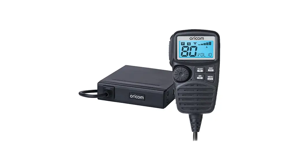
- UHF CB Radio Transceiver
- Heavy Duty Controller Speaker Microphone
- Microphone mounting bracket
- Transceiver mounting bracket
- Pack of supplied mounting screws
- Quick Start Guide
Please read before installing or operating your Oricom radio
The operation of your UHF radio in Australia and New Zealand is subject to conditions in the following licenses: In Australia, the ACMA Radiocommunications (Citizen Band Radio Stations) and in New Zealand by MED the General User Radio License for Citizen Band Radio.
When a new narrowband radio receives a transmission from an older wideband radio the speech may sound loud and distorted – simply adjust your radio volume for the best listening performance. When an older wideband radio receives a signal from a new narrowband radio the speech may sound quieter – simply adjust your radio volume for best listening performance. When operating a narrowband radio or Channel 41 – 80 interference is possible from wideband radios transmitting on high power or on adjacent frequency. The issues described above are not a fault of the radio but a consequence of mixed-use of wideband and narrowband radios.
![]() This unit complies with all relevant Australian and New Zealand approval requirements AS/NZS 4365:2011
This unit complies with all relevant Australian and New Zealand approval requirements AS/NZS 4365:2011
Need help? Contact Oricom Support
If you need assistance setting-up or using your Oricom product now or in the future, call Oricom Support.
Australia
(02) 4574 8888
www.oricom.com.au
Mon-Fri 8 am – 6 pm AEST
New Zealand
0800 67 42 66
Mon-Fri 10 am – 8 pm NZST
Controls and Indicators
Front View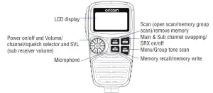 Rear View
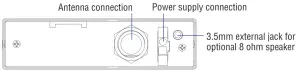 LCD Icons & Indicators.
![]()
- Sub receiver busy
- Sub receiver on
- Main receiver busy
- Duplex on
- Signal strength & TX power
- Group display (A, B, C groups)
- Group address channel
- Status display
- CTCSS or DCS on
- Channel display
Warnings and Safety Information![]() WARNING
WARNING
Potentially Explosive Atmosphere
Turn your radio OFF when in any area with a potentially explosive atmosphere. Sparks in such areas could cause an explosion or fire resulting in injury or even death.
NOTE: Areas with potentially explosive atmospheres are often, but not always clearly marked. They include fueling areas such as below deck on boats; fuel or chemical transfer or storage facilities; areas where the air contains chemicals or particles, such as grain, dust, or metal powders; and any other area where you would normally be advised to turn off your vehicle engine.
Blasting Caps and Areas
To avoid possible interference with blasting operations, turn your radio OFF near electrical blasting caps or in a “blasting area” or in areas posted: “Turn off two-way radios.” Obey all signs and instructions.
Electromagnetic Interference/Compatibility
Nearly every electronic device is susceptible to electromagnetic interference (EMI). To avoid the possibility of electromagnetic interference and/or compatibility conflicts, turn off your radio in any location where posted notices instruct you to do so such as health care facilities.![]() CAUTION
CAUTION
This radio is designed for operation on a 12 Volt battery system. It should not be connected directly to a 24 Volt system. When installing your radio in your vehicle, check that during installation you do not damage any wiring or vehicle components that may be hidden around the mounting position. Ensure the installation does not interfere with the operation of the vehicle and meets all regulatory and safety retirements for accessories fitted to your vehicle. For optimum performance, your radio needs to be installed correctly. If you are unsure about how to install your radio, we suggest you have your radio professionally installed by a UHF specialist or Auto electrician. When installing the radio, avoid mounting it close to heaters or air conditioners. Never press the PTT button before connecting the antenna to the radio.
Installation of Your Oricom Radio
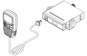
Fitting the Controller Speaker Microphone
The controller speaker microphone uses a 6-pin telephone style plug and socket:
1. Position the microphone plug so the plastic flap faces upward, and insert the plug into the socket until it clicks.
2. Gently press the rubber boot into the hole surrounding the socket so that the slot around the boot fits neatly inside the rim of the entry hole.
Disconnecting the Controller Speaker Microphone
It is recommended that the Controller Speaker Microphone be left permanently connected to the radio, but if it must be disconnected, proceed as follows:
- Lift the rubber boot and the lip of the raised area on the front panel.
- Ease the rubber boot out of the cable entry hole and slide it along the cable away from the front panel.
- Identify the plug locking lever, and move the lever towards the plug body. At the same time gently pull the plug from the socket.
Wiring Methods
There are two possible wiring configurations for connecting to the vehicle’s power supply.
A. Radio stays ON when the ignition is switched OFF
Connect the radio’s negative (black) lead to the vehicle chassis, or directly to the battery’s negative terminal. Connect the radio’s positive (red) lead via the 3 Amp fuse to the battery’s positive terminal. Alternatively, the positive lead could be connected at the fuse box at a point that has DC Power continuously available (preferably the battery side of the ignition switch) via the 3 Amp fuse.
B. Radio turns OFF with the ignition switch
Connect the radio’s negative (black) lead to the vehicle’s chassis, or directly to the battery’s negative terminal. The radio positive (red) lead should connect to an accessory point in the vehicle’s fuse box via the 3 Amp fuse.
Antenna information
The antenna (not supplied) is of critical importance to maximize your output power and receiver sensitivity. A poorly installed, inferior quality antenna, or one not designed for the correct frequency band, will give poor performance. You should only purchase an antenna designed for the 477MHz frequency band.
Antenna installation
To obtain maximum performance from the radio, select a high-quality antenna and mount it in a good location.
Never press the PTT before connecting an antenna to the radio.
Optional accessories
| SPE85 | External speaker If required. you may install an external (8 ohm. Minimum 5W power) speaker fitted with a 3.5mm plug (not supplied). Depending on the installation, it may be necessary to use an external speaker (not supplied) to give improved volume and clarity. This can be plugged into the external speaker (SP) socket on the rear of the unit. |
| MMM100 | Magnetic microphone holder |
Quick Overview of Basic Controls
Turning on the Power
Press and hold the channel selector.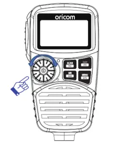
Setting the Volume
Rotate the channel selector clockwise to adjust the sound level for comfortable reception.

Selecting a channel
Press channel selector once. “CH” will appear on the LCD. Select the channel by rotating the channel selector. Turn the channel selector clockwise to adjust channel UP. Turn the channel selector anti-clockwise to adjust the channel DOWN.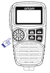
Setting the Squelch Level
1. Press channel selector 2 times. The current squelch level is displayed.
2. Select the squelch level by rotating the channel selector.
1 – Max sensitivity (Min. squelch)
15 – Min. sensitivity (Max/Tight squelch)
Off – Open squelch
Setting SRX (Sub Receiver) Volume
1. Press channel selector 3 times, then “SVL” is displayed.
2. Rotate the channel selector to adjust the SRX volume.
Note :
* If a button is not pressed within 2 seconds the radio will automatically exit the sub-display of “VOL” “CH” “SQL” and “SVL”.
PTT (Push-To-Talk) button
Before transmitting always listen on the channel to make sure it is not being used by another operator. Pressing the PTT allows audio to be transmitted, by speaking across the front on the controller speaker microphone. TX is indicated by the level bars on the LCD display.
To receive, release the PTT button. When transmitting, hold the MIC 5cm from your mouth and speaker clearly in normal voice across the front of the mic.
Factory Reset
If the radio’s display locks up or stops functioning properly, you might need to reset your UHF radio. Caution: This procedure clears all the information you have stored in your UHF radio. Before you reset your UHF radio, try turning it off and on again. If your UHF radio is still not functioning correctly you may need to reset the UHF radio. To reset, press and hold the “PRI/MON” button and power on. “Reset” will appear in the display. The radio will then return to standby mode.
UHF CB channels and frequencies
Channel | Tx | Rx | Channel | Tx | Rx | ||
Freq | Freq | Freq | Freq | ||||
MHZ | MHz | MHz | MHz | ||||
01* | 476.4250 | 476.4250 | 21 | 476.9250 | 476.9250 | ||
41′ | – | 476.4375 | 61: | – | – | ||
02′ | 476.4500 | 476.4500 | 22t | 476.9500 | 476.9500 | ||
42′ | – | 476.4625 | 62: | – | – | ||
03′ | 476.4750 | 476.4750 | 23t | 476.9750 | 476.9750 | ||
43′ | – | 476.4875 | 63: | – | – | ||
| 04′ | 476.5000 | 476.5000 | 24 | 477.0000 | 477.0000 | ||
44′ | – | 476.5125 | 64 | 477.0125 | 477.0125 | ||
05′ | 476.5250 | 476.5250 | 25 | 477.0250 | 477.0250 | ||
45′ | – | 476.5375 | 65 | 477.0375 | 477.0375 | ||
06′ | 476.5500 | 476.5500 | 26 | 477.0500 | 477.0500 | ||
46′ | – | 476.5625 | 66 | 477.0625 | 477.0625 | ||
07′ | 476.5750 | 476.5750 | 27 | 477.0750 | 477.0750 | ||
47′ | – | 476.5875 | 67 | 477.0875 | 477.0875 | ||
08′ | 476.6000 | 476.6000 | 28 | 477.1000 | 477.1000 | ||
48′ | – | 476.6125 | 68 | 477.1125 | 477.1125 | ||
9 | 476.6250 | 476.6250 | 29 | 477.1250 | 477.1250 | ||
49 | 476.6375 | 476.6375 | 69 | 477.1375 | 477.1375 | ||
10 | 476.6500 | 476.6500 | 30 | 477.1500 | 477.1500 | ||
50 | 476.6625 | 476.6625 | 70 | 477.1625 | 477.1625 | ||
I1 | 476.6750 | 476.6750 | 31′ | 477.1750 | 477.1750 | ||
51 | 476.6875 | 476.6875 | 71′ | 477.1875 | – | ||
12 | 476.7000 | 476.7000 | 32′ | 477.2000 | 477.2000 | ||
52 | 476.7125 | 476.7125 | 72′ | 477.2125 | – | ||
13 | 476.7250 | 476.7250 | 33′ | 477.2250 | 477.2250 | ||
53 | 476.7375 | 476.7375 | 73′ | 477.2375 | – | ||
14 | 476.7500 | 476.7500 | 34′ | 477.2500 | 477.2500 | ||
54 | 476.7625 | 476.7625 | 74′ | 477.2625 | – | ||
I5 | 476.7750 | 476.7750 | 35′ | 477.2750 | 477.2750 | ||
55 | 476.7875 | 476.7875 | 75′ | 4771875 | – | ||
16 | 476.8000 | 476.8000 | 36′ | 477.3000 | 477.3000 | ||
56 | 476.8125 | 476.8125 | 76′ | 477.3125 | – | ||
17 | 476.8250 | 476.8250 | 37′ | 477.3250 | 477.3250 | ||
57 | 476.8375 | 476.8375 | 77′ | 477.3375 | – | ||
18 | 476.8500 | 476.8500 | 38′ | 477.3500 | 477.3500 | ||
58 | 476.8625 | 476.8625 | 78′ | 477.3625 | – | ||
19 | 476.8750 | 476.8750 | 39 | 477.3750 | 477.3750 | ||
59 | 476.8875 | 476.8875 | 79 | 477.3875 | 477.3875 | ||
20 | 476.9000 | 476.9000 | 40 | 477.4000 | 477.4000 | ||
| 60 | 476.9125 | 476.9125 | 80 | 477.4125 | 477.4125 | ||
* The primary use for these channels is repeater operation using 750 kHz offset. Channels 1-8 inclusive are used for mobile reception and channels 31-38 for mobile transmission. They may also
EMC Technologies (NZ) Ltd
STREET ADDRESS – 47 MacKelvie Street, Grey Lynn, Auckland, NZ
Phone: +64 9 360 0862 Fax: +64 9 360 0861
POSTAL ADDRESS – PO Box 68 307, Newton, Auckland, New Zealand
E-mail: [email protected]
Page 11 of 23 This report may not be reproduced except in full
* The primary use for these channels is repeater operation using 750 kHz offset. Channels 1-8 inclusive are used for mobile reception and channels 31-38 for mobile transmission. Note that additional channels 41-48 and 71-78 are also available for repeater operation to supplement channels 1-8 and-31-38 respectively as approved by the ACMA CBRS Class Licence in Australia and the MED GURL in New Zealand. In addition, any designated repeater channel may be used for simplex operation in areas where it is not used for repeater operation.
† Speech telephony shall be inhibited on these channels.
‡ At the time of production Channels 61, 62, and 63 are guard channels and are not available for use.
Channel 5 and 35 (paired for Duplex repeaters) are reserved as emergency channels and should be used only in an emergency.
CTCSS and DCS will not operate on these channels. A list of currently authorized channels can be obtained from the ACMA website in Australia and the MED website in New Zealand. Channel 11 is a calling channel generally used to call others and channel 40 is the customary road vehicle channel. Once contact is established on the calling channel, both stations should move to another unused “SIMPLEX” channel to allow others to use the calling channel. Channels 22 and 23 are for Telemetry and Telecommand use, voice communications are not allowed on these channels by law. Channel 9 and above are the best choices for general use in Simplex mode.
Express Warranty (Australia)
This Express Warranty is provided by Oricom International Pty Ltd ABN 46 086 116 369, Unit 1, 4 Sovereign Place, South Windsor NSW 2756, hereinafter referred to as “Oricom”.
Oricom products come with guarantees that cannot be excluded under the Australian Consumer Law. You are entitled to a replacement or refund for a major failure and compensation for any other reasonably foreseeable loss or damage. You are also entitled to have the goods repaired or replaced if the goods fail to be of acceptable quality and the failure does not amount to a major failure. Oricom warrants that the product is free from defects in materials or workmanship during the Express Warranty Period. This Express Warranty does not extend to any product from which the serial number has been removed or was purchased outside of Australia.
Nothing in this Express Warranty excludes, restricts, or modifies any condition, warranty, guarantee, implied term, right or remedy pursuant to the Australian Consumer Law and which may not be so excluded, restricted or modified. For such conditions, terms, guarantees, and warranties that cannot be excluded, restricted or modified, Oricom limits the remedies available to the extent permitted in the relevant legislation.
The Express Warranty Period will be 5 years from the date of purchase of the product evidenced by your dated sales receipt. You are required to provide proof of purchase as a condition of receiving Express Warranty services.
You are entitled to a replacement product or repair of the product at our discretion according to the terms and conditions of this document if your product is found to be faulty within the Express Warranty Period. This Express Warranty extends to the original purchaser only and is not transferable.
Products distributed by Oricom are manufactured using new materials or new and used materials equivalent to new in performance and reliability. Spare parts may be new or equivalent to new. Spare parts are warranted to be free from defects in material or workmanship for thirty (30) days or for the remainder of the Express Warranty Period of the Oricom branded product in which they are installed, whichever is longer. During the Express Warranty Period, Oricom will where possible repair and if not replace the faulty product or part thereof. All component parts removed under this Express Warranty become the property of Oricom. In the unlikely event that your Oricom product has a recurring failure, Oricom may always, subject to the Competition and Consumer Act 2010, at its discretion, elect to provide you with a replacement product of its choosing that is at least equivalent to your product in performance.
No change to the conditions of this Express Warranty is valid unless it is made in writing and signed by an authorized representative of Oricom.
Oricom will not be liable under this Express Warranty, and to the extent permitted by law will not be liable for any defect, loss, damage or injury arising out of or in connection with a:
- Failure by you to adhere to the warnings and follow the instructions set out in this user guide for the proper installation and use of the product;
- Wilful misconduct or deliberate misuse by you of the product;
- Any external cause beyond our control, including but not limited to power failure, lightning or over voltage; or
- Modification to the product or services carried out on the product by anyone other than Oricom or Oricom’s authorized service provider.
How to make a claim under your Express Warranty in Australia
Oricom has a simple warranty process for you to follow:
- Please call or email our Customer Support Team, (02) 4574 8888 or [email protected].
- A Customer Support Team member will verify after troubleshooting with you if your product qualifies under warranty. If so, they will give you a Product Return Authorization number.
- We will then email or fax a Return Authorisation Form and a Repair Notice (if necessary), together with instructions on
how to return the goods for warranty service.
Please note that if a Customer Support Team member advises that your product does not qualify for a return, this warranty
does not apply to your product. Products that are authorized to be returned to Oricom in Australia must include all of the
following: - A completed Return Authorisation form
- A copy of your Proof of Purchase (please keep your original copy)
- The faulty product, including all accessories.
Send the approved returns to:
Oricom International Pty Ltd
Locked Bag 658
South Windsor NSW 2756 Australia
Please note that this Express Warranty excludes expenses incurred by you in returning any faulty product to us. You must arrange and pay any expenses incurred (including postage, delivery, freight, transportation, or insurance of the product) to return the faulty product to us, however, we will arrange delivery of the repaired or replaced faulty product to you.
Important Information
Repair Notice
Please be aware that the repair of your goods may result in the loss of any user-generated data (such as stored telephone numbers, text messages, and contact information). Please ensure that you have made a copy of any data saved on your goods before sending it for repair. Please also be aware that goods presented for repair may be replaced by refurbished goods or parts of the same type rather than being repaired.


