![]() User Manual
User Manual
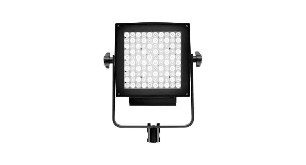
Action panel FULL COLOR
Release 4.xx
SAFETY PRECAUTIONS
Do not operate the equipment before studying the instruction manual and the accompanying safety precautions. Make sure that Lupo Safety Instruction is always included with the equipment! Lupo products are intended for professional use. Do not place or use the equipment where it can be exposed to moisture, extreme electromagnetic fields or in areas with flammable gases or dust! Do not expose the equipment to hasty temperature changes in humid condition as could lead to condensation water in the unit. Equipment must only be serviced, modified or repaired by authorized. Dealers or the factory.
CAUTION – BURN HAZARD – HOT PARTS
Do not touch hot parts with bare fingers! LED bulbs and certain metal parts emit strong heat when used!
Do not point lamps too close to persons. Always use the fixtures with the front part closed.
NOTICE – EQUIPMENT OVERHEATING RISK
Do not obstruct ventilation by placing filters, diffusing materials, etc. over inlets and outlets of the equipment ventilation or directly over glass cover or LED bulbs.
FINAL DISPOSAL
Equipment contains electrical and electronic components that could be harmful to the environment.Equipment may be returned to Lupo distributors free of charge for recycling according to WEEE. Follow local legal requirements for separate disposal of waste, for instance WEEE directive for electrical and electronic equipment on the European market, when product life has ended.
MAINTENANCE AND CARE
Please do not forget that the safe operation of lamp heads also includes their maintenance and care. A visual inspection should be conducted before every use and an inspection of electrical safety should be conducted at least once every 12 months.
WARRANTY
The warranty period for Lupo products and those marketed by Lupe is twelve months from the date of delivery. Lupe guarantees that the goods it supplies are well manufactured and of good quality. The warranty guarantees the repair of any parts that show acknowledged defects in materials, construction or workmanship during the warranty period. The guarantee excludes any liability for direct or indirect damage of any kind and for any reason, for which Lupe will therefore not be required to pay compensation. The customers shall see to deliver the parts that need repair or replacement to Lupus works at their own expense and risk. The repaired or replacement parts shall be delivered by Lupo ex-works. The customers will be charged for materials and labor or replacement of the product after the expiration of the warranty period.![]() WARNING:
WARNING:
When hanging the fixture from higher position, please make sure you use safety cable to attach the barn doors to the yoke of the panel.
Barn doors should always be used to secure the fixture and the application when used in this way.
Another safety cable should be used to secure the fixture to the mounting pipe or truss.
Both safety cables must be properly dimension ed for the fixture and the application when the fixture is operated in hanging position please ensure that the accessories are installed correctly with top latch locked.
ATTENTION: Please keep the original package of the product in a safe place for warranty reasons.
Thanks for having purchased Lupo products. All the products are made in Italy and all the efforts have been put to keep the quality standards high. We hope this product can help you in your job and make your life easier as a professional. We also hope you will enjoy its use and we would be happy to receive your feedback about it.
Instructions
- Device for indoor use only.
- Maximum ambient temperature: 40 °C.
- Make sure power supply plug is suitable to power required.
- As prescribed by international regulations, a safety cable must be used when the fixture is suspended from ceiling.
- To switch on the light push the on/off button.
- Action panel models are equipped with new generation high quality powerless.
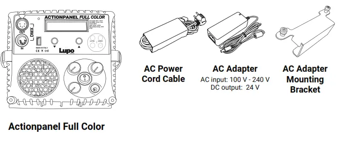
Getting Started
Turning on the Action panel
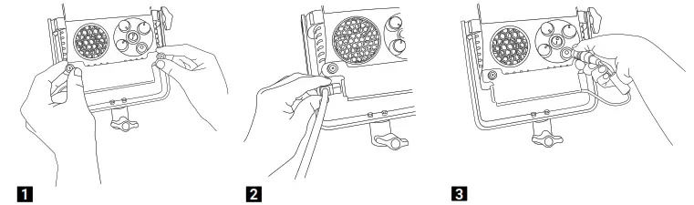
- Place the AC Adapter in the mounting bracket via the 2 captive screws to the bottom of the ACTION PANEL fixture.
- Insert the power cord cable into the AC adapter and connect the fixture to the power plug.
- Insert the DC connector into the input jack on the ACTION PANEL and power on the fixture.
Functioning
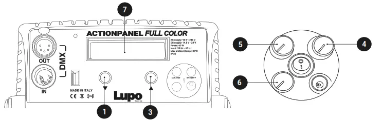
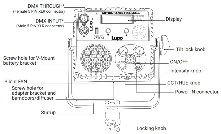
CONTROL PANEL
- In current mode press the 5 push button to enter the main MENU.
- In the sub-menus press the 5 push button to confirm a selection.
- Rotate the 5 knob to navigate in the main MENU and sub-menus.
- Use the « INTENSITY » 4 knob to adjust the light intensity from 0 to 100%.
- Use the knobs 5 and 6 to adjust the light mode parameters.
- Display 7 .
![]() ATTENTION: The light intensity level is adjustable from 0 – 50% if the FAN is OFF. The value on the display flashes.
ATTENTION: The light intensity level is adjustable from 0 – 50% if the FAN is OFF. The value on the display flashes.
MANUAL OPERATION
- Press the 5 push button to enter the main MENU.
- Select MANUAL by pressing the 5 push button.
- Select the light mode between CCT / HSI / RGBW / PRESET / EFFECT with the 5 knob and press the 5 push button to confirm selection.
- See LIGHT MODES.
DMX OPERATION
- Press the 5 push button to enter the main MENU.
- Select DMX with the 5 knob and press the 5 push button to confirm selection.
- Select the light mode between CCT / HSI / RGBW / FRGBW / PRESET / EFFECT with the 5 knob and press the 5 push button to confirm selection.
- Select the DMX channel, rotating the 5 knob to change DMX ADDRESS in ascending or descending order between 1 and 512. The number shown on the display 7 is the selected channel to communicate with the control desk.
- See DMX PROTOCOL MANUAL to DMX channel specification.
NOTE: The symbol – ! – on the display indicates that there is no DMX signal.
BLUETOOTH
Enable / Disable BLE App interface
DMX OPERATION – Advanced Settings
- Press the 5 push button to enter the main MENU.
- Navigate through the main MENU with the 5 knob and press the 5 push button to confirm selection.
- Rotate the 5 knob to select DMX ADVANCED, press the 5 push button to confirm selection.
- Select one of the options among the DMX BIT, DMX SIGNAL LOSS and RDM ENABLE, press 5 push button to confirm the selection.
DMX BIT:
Resolution of the DMX control. 8bit 1 channel per function and 16 bit 2 channels per function.
- Select the DMX BIT item by pressing the 5 push button.
- Rotate the 5 knob to choose between 8bit / 16bit, press the 5 push button to confirm the selected setting. See DMX PROTOCOL MANUAL.
DMX SIGNAL LOSS:
This feature allows to choose the device’s behaviour in case of a DMX signal loss.
- Select the LOSS DMX SIGNAL item with the 5 push button
- Rotate the 5 knob to select the device’s behaviour between BLACK OUT /SETTINGS
LAST / SETTINGS 1min, press the 5 push button to confirm the setting.
Black out: The device switches off.
Settings Last: The values of the last selected setting are maintained over time until the device is switched off.
Settings 1min: The values of the last selected settings is maintained for one minute and then the device is switch off.
RDM Enable: ON/OFF, enable/disable RDM Protocol
LIGHT MODES
| MODE | INTENSITY 4 | CCT/HUE 5 | GN/SAT/COLOR 6 | « » 1 « » 3 |
| CCT | Light Intensity from 0 to 100% | CT 2800K to 10000K | GN -1.00 to +1.00 | – |
| HSI | HUE 0º to 100º | SAT 0 to 100% | – | |
| RGBW | – | Select function R/G/B/W/CT/GN | Change values of the function | |
| PRESET | – | – | Change Preset | |
| EFFECT | “See EFFECT table” | “See EFFECT table” | Change Effect |
In CCT, HSI, RGBW and PRESET Mode, the «![]() » key selects the STROBE page and the «
» key selects the STROBE page and the «![]() » key exits the STROBE PAGE.
» key exits the STROBE PAGE.
* In the STROBE PAGE it is possible to set DIMMER value and the STROBE frequency by rotating the 5 button.
ATTENTION: STROBE frequency = 0 means STROBE effect OFF.
A. CCT MODE: Warm and cold white control mode. It allows you to adjust colour temperature (CCT), green/magenta compensation (GN) and light intensity. This is the default setting.
B. HSI MODE: Colour composition mode. It allows you to adjust hue of colour (HUE), colour saturation (SAT) and light intensity.
C. RGBW MODE: RGBW colour control mode allows to individually set the R, G, B, W, Color
Temperature (CT), green/magenta compensation (GN) values and to adjust light intensity
D. FRGBW MODE: Available only in DMX operation. Same as RGBW but with white color power unlimited. See DMX PROTOCOL MANUAL.
E. PRESET MODE: Mode with 53 PRESET colors, 48 factory preset and 5 user-defined preset.
- In MANUAL OPTIONS or DMX MODE menu select PRESET MODE.
- Select the PRESET to be activated rotate the 5 button, confirm the selection by pressing the 5 push button.
- Use the « INTENSITY » 4 knob to adjust the light intensity from 0 to 100%.
SAVING THE SET VALUES AS A PRESET
You can store up to 5 PRESETS.
- In MANUAL select SAVE PRESET by pressing the 5 push button.
- Save the set values in one of the available presets between USER PRESET 1 / 2 / 3 / 4 / 5 rotate the 5 knob to select the PRESET number and press the 5 push button to confirm the selection. THE SET COLOR IS SAVED AS PRESET.
“BUSY” indicates that in the user preset there are parameters memorized if you select it, the parameters is replaced by the new ones. “EMPTY” indicates that the user preset is free.
E. SPECIAL EFFECT MODE: Mode with 11 SPECIAL EFFECTS. PARTY / COPCAR / DISCO 1 / DISCO 2 / TELEVISION BW / TELEVISION CO / PAPARAZZI / LIGHTNING / EXPLOSION / FIREWORKS / FIRE.
- In MANUAL OPTIONS or DMX MODE menu select EFFECT MODE.
- Select the EFFECT to be activated with rotate the 5 button, confirm the selection by pressing the 5 push button.
- In current mode, use the « » 1 o « » 3 button to change the EFFECT in ascending or descending order. THE EFFECT ON THE DISPLAY IS THE SELECTED EFFECT.
- Use the knobs 5 and 6 to adjust the effect setting values. See table below.
| EFFECT | 4 INTENSITY knob | 5 CCT/HUE knob | 6 GN/SAT/COLOR knob |
| PARTY | Light Intensity from 0 to 100% | Speed – 0 to 100% | – |
| COPCAR | Flash Color – B / R / R+B / B+W / R+B+W | Nº flashes for cycle – 1 to 4 | |
| DISCO 1 | Speed – 0 to 100% | – | |
| DISCO 2 | Speed – 0 to 100% | – | |
| TELEVISION BW | Light Intensity from 0 to 100% | White range – 1 / 2 / 3 / 4 | Frequency – 4 to 24 Hz |
| TELEVISION CO | White range – 1 / 2 / 3 / 4 | Frequency – 4 to 24 Hz | |
| PAPARAZZI | Flashing Interval – 1 to 10 | Bulb type – 0 / 1 / 2 | |
| LIGHTNING | Color Temperature | Lightnings Interval – 1 to 20 | |
| EXPLOSION | Speed – 1 to 60 | – | |
| FIREWORKS | Speed – 1 to 60 | – | |
| FIRE | Speed – 1 to 3 | – |
DEVICE SETTINGS
- Press the 5 push button to enter the main MENU.
- Navigate through the MENU rotating the 5 button, select DEVICE SETTINGS, press the 5
push button to confirm the selection. - Navigate through the FAN / DISPLAY / MENU VIEW / FILTER / LINEARIZATION / CCT LIMIT functions, rotating the 5 button to select the desired function and press the 5 push button to confirm the selection.
- Within each function select the option to be activated and rotate the 5 button.
Fan: Fan operation. ON / OFF.
When the fan is OFF the light intensity is adjustable between 0 and 50%.
Display: Time during which the display backlight stays on. 30sec / 1min / ALWAYS ON.
Menu View: Type the main MENU, sub-menus and functions to show. ONLY MANUAL /
ONLY DMX / MANUAL/DMX.
Filter: It is the speed response of the system (smooth factor).
FULL SPEED / NORMAL SPEED / HIGH SPEED / LOW SPEED.
Militarization: Militarization is the compensation curve for the human eye’s perception of the luminous intensity emitted as a function of the required power. Required power = dimmer value on the display. LINEAR / EXPONENTIAL / LOGARITHMIC.
Linear: No compensation, the intensity of the light is directly proportional to requested power.
Exponential: The light intensity increases from 0 to 100 exponentially.
Logarithmic: The light intensity increases from 0 to 100 logarithmically.
CCT Limit: The colour temperature is limited. 3200K – 5600K / 2800K – 10000K.
RESET DEVICE
- Press the « OK » 2 button to enter the main MENU.
- Select RESET DEVICE rotating the 5 button, press the 5 push button to confirm the selection.
- Select YES rotating the 5 button, press the 5 push button to confirm the selection.
- The device ask for further confirmation, select YES by pressing the press the 5 push button.THE DEVICE RETURN TO FACTORY DEFAULT SETTINGS.
FACTORY DEFAULT SETTING
| MANUAL OPERATION MODE: CCT DMX OPERATION MODE: CCT BIT: 8 BIT DMX SIGNAL LOSS: Settings 1 MIN RDM ENABLE: OFF | DEVICE SETTINGS FAN: ON DISPLAY: 1 min MENU VIEW : Manual/DMX FILTER : Normal speed LINEARIZATION: Linear CCT LIMIT: 2800K – 10000K BLUETOOTH Bluetooth Active: OFF |
Package Contents
![]() ATTENTION: Please keep the original package of the product in a safe place for warranty reasons.
ATTENTION: Please keep the original package of the product in a safe place for warranty reasons.
USB port
Use USB port for firmware updates.
Update the Firmware
- Copy the file on an USB Pen drive (FAT32 formatted) in the main root;
- Switch off the equipment and insert the USB Pen drive;
- Switch on the equipment;
- Wait until display backlight flashes (it takes several minutes and red led must toggle for all time long);
- Switch off the equipment;
- Extract the Pen drive and switch on the equipment: the firmware is updated.
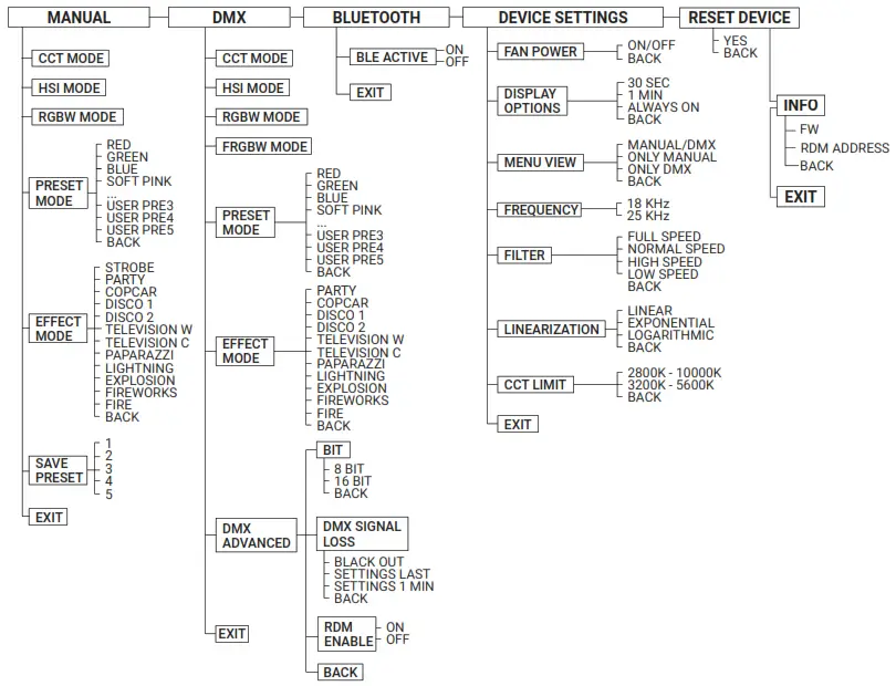
MENU e sub menus
DMX Protocol
Introduction
The Action panel Full Color can be used with 8 bit or 16 bit DMX control.
(See DMX OPERATION – advanced settings in the user’s manual).
When used in 8 bit mode the Action panel Full Color uses one channel for each function. DMX values for each channel are in the range of 0 to 255.
When used in 16 bit mode the Action panel Full Color uses two channels for each function. The increased resolution offers a smooth dimming and a more accurate color adjustment. DMX values for the first channel (byte
- are in the range of 256 to 65535 while for the second channel (byte 2) they are in the range of 0 to 255.
The fixture use the number of channels required based on the light mode selected CCT / HSI / RGBW /PRESET / PARTY / COPCAR / DISCO 1 / DISCO2 / TELEVISION 1 / TELEVISION 2 / PAPARAZZI / LIGHTNING /EXPLOSION / FIREWORKS / FIRE.
The Action panel Full Color uses consecutive channels starting from the DMX channel set on the panel (DMX address) used as reference for the connection to the control desk. Please take the above into consideration when using many units of Action panel Full Color to avoid overlaps.![]() ATTENTION: The symbol – ! – on the display indicates that there is no DMX signal.
ATTENTION: The symbol – ! – on the display indicates that there is no DMX signal.
| MODE | CHANNELS USED | DMX CHANNEL POSITION |
| CCT | 4 | 1. DIMMER |
| 2. COLOR TEMPERATURE | ||
| 3. GN COMPENSATION | ||
| 4. STROBE | ||
| HSI | 4 | 1. DIMMER |
| 2. HUE | ||
| 3. SATURATION | ||
| 4. STROBE | ||
| RGBW | 8 | 1. DIMMER |
| 2. RED | ||
| 3. GREEN | ||
| 4. BLUE | ||
| 5. WHITE | ||
| 6. COLOR TEMPERATURE | ||
| 7. GN COMPENSATION | ||
| 8. STROBE | ||
| FRGBW | 8 | 1. DIMMER |
| 2. RED | ||
| 3. GREEN | ||
| 4. BLUE | ||
| 5. WHITE | ||
| 6. COLOR TEMPERATURE | ||
| 7. GN COMPENSATION | ||
| 8. STROBE | ||
| PRESET | 4 | 1. DIMMER |
| 2. STROBE | ||
| 3. PRESET | ||
| 4. PRESET FREEZE | ||
| PARTY | 2 | 1. DIMMER |
| 2. SPEED | ||
| COPCAR | 3 | 1. DIMMER |
| 2. NUMBER OF COLORS | ||
| 3. NUMBER OF FLASH | ||
| DISCO 1 | 2 | 1. DIMMER |
| 2. SPEED | ||
| DISCO 2 | 2 | 1. DIMMER |
| 2. SPEED | ||
| TELEVISION 1 | 3 | 1. DIMMER |
| 2. WHITE RANGE | ||
| 3. FREQUENCY | ||
| TELEVISION 2 | 3 | 1. DIMMER |
| 2. WHITE RANGE | ||
| 3. FREQUENCY | ||
| PAPARAZZI | 3 | 1. DIMMER |
| 2. INTERVAL | ||
| 3. BULB TYPE | ||
| LIGHTNING | 3 | 1. DIMMER |
| 2. COLOR TEMPERATURE | ||
| 3. INTERVAL | ||
| EXPLOSION | 2 | 1. DIMMER |
| 2. SPEED | ||
| FIREWORKS | 2 | 1. DIMMER |
| 2. SPEED | ||
| FIRE | 2 | 1. DIMMER |
| 2. SPEED |
DMX Channel Protocol – 16 bit
| MODE | CHANNELS USED | DMX CHANNEL POSITION |
| CCT | 8 | 1. DIMMER – byte 1 |
| 2. DIMMER – byte 2 | ||
| 3. COLOR TEMPERATURE – byte 1 | ||
| 4. COLOR TEMPERATURE – byte 2 | ||
| 5. GN COMPRENSATION – byte 1 | ||
| 6. GN COMPENSATION – byte 2 | ||
| 7. STROBE – byte 1 | ||
| 8. STROBE – byte 2 | ||
| HSI | 8 | 1. DIMMER – byte 1 |
| 2. DIMMER – byte 2 | ||
| 3. HUE – byte 1 | ||
| 4. HUE – byte 2 | ||
| 5. SATURATION – byte 1 | ||
| 6. SATURATION – byte 2 | ||
| 7. STROBE – byte 1 | ||
| 8. STROBE – byte 2 | ||
| RGBW | 16 | 1. DIMMER – byte 1 |
| 2. DIMMER – byte 2 | ||
| 3. RED – byte 1 | ||
| 4. RED – byte 2 | ||
| 5. GREEN – byte 1 | ||
| 6. GREEN – byte 2 | ||
| 7. BLUE – byte 1 | ||
| 8. BLUE – byte 2 | ||
| 9. WHITE – byte 1 | ||
| 10. WHITE – byte 2 | ||
| 11. COLOR TEMPERATURE – byte 1 | ||
| 12. COLOR TEMPERATURE – byte 2 | ||
| 13. GN COMPENSATION – byte 1 | ||
| 14. GN COMPENSATION – byte 2 | ||
| 15. STROBE – byte 1 | ||
| 16. STROBE – byte 2 | ||
| FRGBW | 14 | 1. DIMMER – byte 1 |
| 2. DIMMER – byte 2 | ||
| 3. RED – byte 1 | ||
| 4. RED – byte 2 | ||
| 5. GREEN – byte 1 | ||
| 6. GREEN – byte 2 | ||
| 7. BLUE – byte 1 | ||
| 8. BLUE – byte 2 | ||
| FRGBW | 14 | 9. WHITE – byte 1 |
| 10. WHITE – byte 2 | ||
| 11. COLOR TEMPERATURE – byte 1 | ||
| 12. COLOR TEMPERATURE – byte 2 | ||
| 13. GN COMPENSATION – byte 1 | ||
| 14. GN COMPENSATION – byte 2 | ||
| PRESET | 8 | 1. DIMMER – byte 1 |
| 2. DIMMER – byte 2 | ||
| 3. STROBE – byte 1 | ||
| 4. STROBE – byte 2 | ||
| 5. PRESET – byte 1 | ||
| 6. PRESET – byte 2 | ||
| 7. PRESET FREEZE – byte 1 | ||
| 8. PRESET FREEZE – byte 2 | ||
| PARTY | 4 | 1. DIMMER – byte 1 |
| 2. DIMMER – byte 2 | ||
| 3. SPEED – byte 1 | ||
| 4. SPEED – byte 2 |
| COPCAR | 6 | 1. DIMMER – byte 1 |
| 2. DIMMER – byte 2 | ||
| 3. NUMBER OF COLORS – byte 1 | ||
| 4. NUMBER OF COLORS – byte 2 | ||
| 5. NUMBER OF FLASH – byte 1 | ||
| 6. NUMBER OF FLASH – byte 2 | ||
| DISCO 1 | 4 | 1. DIMMER – byte 1 |
| 2. DIMMER – byte 2 | ||
| 3. SPEED – byte 1 | ||
| 4. SPEED – byte 2 | ||
| DISCO 2 | 4 | 1. DIMMER – byte 1 |
| 2. DIMMER – byte 2 | ||
| 3. SPEED – byte 1 | ||
| 4. SPEED – byte 2 | ||
| TELEVISION 1 | 6 | 1. DIMMER – byte 1 |
| 2. DIMMER – byte 2 | ||
| 3. WHITE RANGE – byte 1 | ||
| 4. WHITE RANGE – byte 2 | ||
| 5. FREQUENCY – byte 1 | ||
| 6. FREQUENCY – byte 2 | ||
| TELEVISION 2 | 6 | 1. DIMMER – byte 1 |
| 2. DIMMER – byte 2 | ||
| 3. WHITE RANGE – byte 1 | ||
| 4. WHITE RANGE – byte 2 | ||
| 5. FREQUENCY – byte 1 | ||
| 6. FREQUENCY – byte 2 | ||
| PAPARAZZI | 6 | 1. DIMMER – byte 1 |
| 2. DIMMER – byte 2 | ||
| 3. INTERVAL – byte 1 | ||
| 4. INTERVAL – byte 2 | ||
| 5. BULB TYPE – byte 1 | ||
| 6. BULB TYPE – byte 2 | ||
| LIGHTNING | 6 | 1. DIMMER – byte 1 |
| 2. DIMMER – byte 2 | ||
| 3. COLOR TEMPERATURE – byte 1 | ||
| 4. COLOR TEMPERATURE – byte 2 | ||
| 5. INTERVAL – byte 1 | ||
| 6. INTERVAL – byte 2 | ||
| EXPLOSION | 4 | 1. DIMMER – byte 1 |
| 2. DIMMER – byte 2 | ||
| 3. SPEED – byte 1 | ||
| 4. SPEED – byte 2 | ||
| FIREWORKS | 4 | 1. DIMMER – byte 1 |
| 2. DIMMER – byte 2 | ||
| 3. SPEED – byte 1 | ||
| 4. SPEED – byte 2 | ||
| FIRE | 4 | 1. DIMMER – byte 1 |
| 2. DIMMER – byte 2 | ||
| 3. SPEED – byte 1 | ||
| 4. SPEED – byte 2 |
RDM Protocol Specification
| COMMAND | PID | DESCRIPTION |
| Manufacturer ID | 0x0622 | Manufacturer identification number (LUPO Lighting). |
| Device Identification | ||
| Model ID | Model identification number | |
| 0x0000 | Dayled 650 mono color | |
| 0x0001 | Day led 650 dual color | |
| 0x0002 | Day led 1000 mono color | |
| 0x0003 | Day led 1000 dual color | |
| 0x0004 | Day led 2000 mono color | |
| 0x0005 | Day led 2000 dual color | |
| 0x0006 | Super panel 30 dual color soft | |
| 0x0007 | Super panel 30 dual color lens | |
| 0x0008 | Super panel 30 full color soft | |
| 0x0009 | Super panel 30 full color lens | |
| 0x0010 | Super panel 60 dual color soft | |
| 0x0011 | Super panel 60 dual color lens | |
| 0x0012 | Super panel 60 full color soft | |
| 0x0013 | Super panel 60 fullcolor lens | |
| 0x0014 | Action panel dual color soft | |
| 0x0015 | Action panel dual color lens | |
| 0x0016 | Action panel full color soft | |
| 0x0017 | Action panel full color lens | |
| 0x0018 | Kick ass panel dual color | |
| 0x0019 | Kick ass panel full color | |
| 0x0020 | Lu poled mono color | |
| 0x0021 | Lu poled dual color | |
| Personality | DMX Personality | |
| 0x00 | CCT | |
| 0x01 | HSI | |
| 0x02 | RGBW | |
| 0x03 | FRGBW | |
| 0x04 | PRESET | |
| 0x05 | PARTY | |
| 0x06 | COPCAR | |
| 0x07 | DISCO 1 | |
| 0x08 | DISCO 2 | |
| 0x09 | TELEVISION BW | |
| 0x0A | TELEVISION CO | |
| 0x0B | PAPARAZZI | |
| 0x0C | LIGHTNING | |
| 0x0D | EXPLOSION | |
| 0x0E | FIREWORKS | |
| 0x0F | FIRE | |
| Network management | ||
| DISC UNIQUE BRANCH | 0x0001 | Search RDM devices |
| DISC MUTE | 0x0002 | Mute RDM device, no response message |
| DISC UN MUTE | 0x0003 | Activate RDM device fo response message |
| Status collection | ||
| QUEUED MESAGES | 0x0020 | Retrieves queued messages or status message if no message is in queue |
| STATUS MESSAGES | 0x0030 | Retrieves current Warning/Error messages |
| RDM Information | ||
| SUPPORTED PARAMETERS | 0x0050 | Retrieves a list of all supported RDM commands |
| PARAMETER DESCRIPTION | 0x0051 | Retrieves a list of all RDM commands |
| Product Information | ||
| DEVICE INFO | 0x0060 | Retrieves a variety of information about the device that is normally required by a controller. |
| DEVICE MODEL DESCRIPTION | 0x0080 | Text description of up to 32 characters for the device model type. |
| MANUFACTURER LABEL | 0x0081 | This parameter provides an ASCII text response with the Manufacturer name for the device. “LUPO” is the default name. |
| FACTORY DEFAULTS | 0x0090 | Set the device to its factory defaults. Get: Check if settings still in default state -> 1 if default |
| SOFTWARE VERSION LABEL | 0x00C0 | Retrieves software version string of main software |
| DMX512 Setup | ||
| DMX PERSONALITY | 0x00E0 | DMX mode |
| DMX PERSONALITY DESCRIPTION | 0x00E1 | Shows a description of a DMX-Mode, max 32 characters |
| DMX START ADDRESS | 0x00F0 | DMX address |
| Control | ||
| IDENTIFY DEVICE | 0x1000 | The identify flag (flashes the light) |
| Manufacturer Commands | ||
| FAN MODE | 0x8001 | 0: Off 1: On |
| DISPLAY TIMEOUT | 0x8002 | 0: 30 sec 1: 1 min 2: always on |
| DMX SIGNAL LOST MODE | 0x8003 | 0: black out 1: last settings on 2: last settings 1 min |
| DMX BITS | 0x8004 | 0: 8 bit 1: 16 bit |
| CCT LIMIT | 0x8005 | 0: 2800-10000 1: 3200-5600 |
| MILITARIZATION | 0x8006 | 0: linear 1: exponential 2: logarithmic |
| FILTER | 0x8007 | 0: full speed 1: normal speed 2: high speed 3: low speed |
![]() Lupe srl – Via V. Sassi 28
Lupe srl – Via V. Sassi 28
30 College (TO) – 10093 – Italy
Phone: +39 011 411 9919
e-mail: [email protected]
website: www.lupo.it


