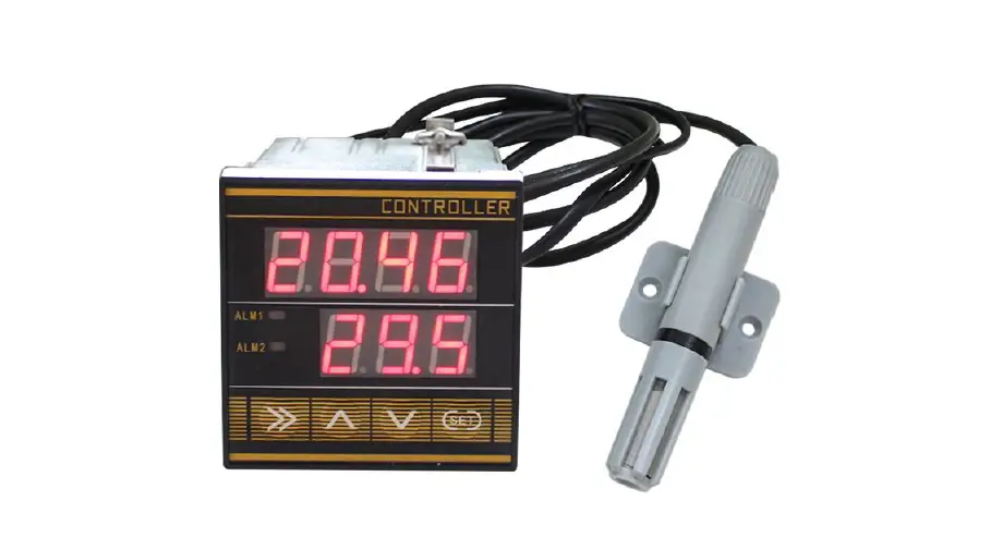
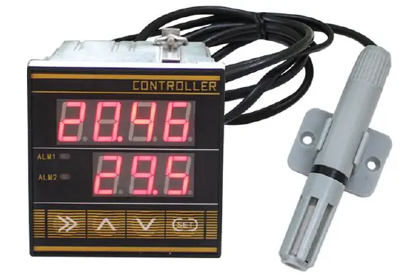
SONBEST RS485 Interface with Communication Function Temperature and Humidity Controller
SC7210B u sing the standard RS485 bus MODBUS RTU protocol,easy access to PLC DCS and other instruments or systems for monitoring temperature,humidity state quantities.The internal use of high precision sensing core and related devices to ensure high r eliability and excellent long term stability,can be customized RS232,RS485,CAN,4 20mA,DC0~5V 10V,ZIGBEE,Lora,WIFI,GPRS and
other output methods.
Technical Parameters
| Technical parameter | Parameter value |
| Brand | SONBEST |
| Temperature measuring range | -30℃~80℃ |
| Temperature measuring accuracy | ±0.5℃ @25℃ |
| Humidity measuring range | 0~100%RH |
| Humidity accuracy | ±3%RH @25℃ |
| Communication Interface | RS485 |
| Default baud rate | 9600 8 n 1 |
| Power | AC185~265V 1A |
| Control mode | Relay |
| carrying capacity | 10A 220VAC |
| Running temperature | -40~80°C |
| Working humidity | 5%RH~90%RH |
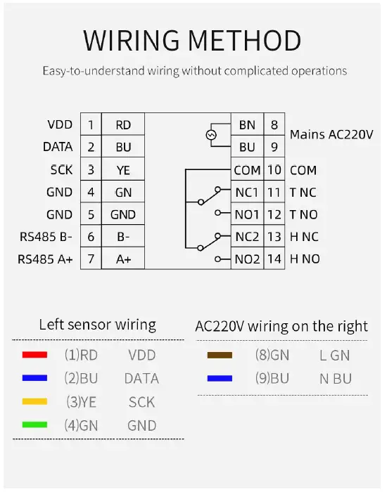
How to wiring?
WIRING METHOD
Easy-to-understand wiring without complicated operations
DETAILED KEYS
Standard MODBUS-RTU protocol, default baud rate is 9600, invalid check, 8 data bits, software can change threshold and other parameters, and query lighting data in real time through RS485
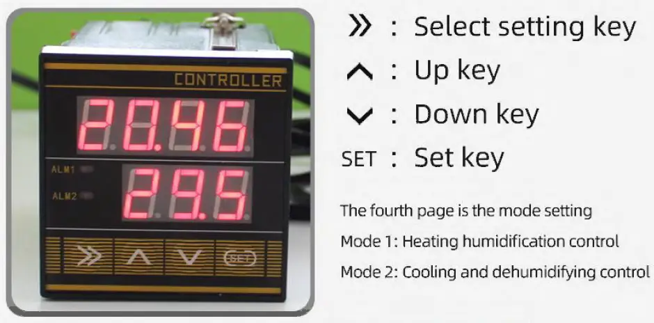
The upper part is the temperature display value
The lower part is the humidity display value.
- Press and hold SET for two seconds and release it to enter the heating and humidifying control setting.
Press }) to select the position, press /\, and V to adjust the value model , the controller will act when the value is lower than the lower limit threshold.
Upper threshold: Minimum temperature 0, maximum 99.9
Humidity minimum 0, maximum 99.9 - Press SET to enter the cooling and dehumidifying control setting
- Press }) to select the posit ion, press /\ and 11V11 to adjust the value
In mode 2, the controller will act when the value is higher than the upper th reshold.
Lower limit threshold: Minimum temperature -30, maximum 99.9
Humidity minimum 0, maximum 99.9 - Press SET twice to enter the control hysteresis setting
Press }) to select the position, press /\ and V to adjustthe value.
Hysteres is: Minimum temperature 0, maximum 10
Humidity minimum 0, maximum 10 - Press SET three times to enter the control mode setting
Press }) to select the posit ion, press /\ and V to adjustthe value.
Mode 1: Action below the lower limit threshold
Mode 2: Action above the upper threshold
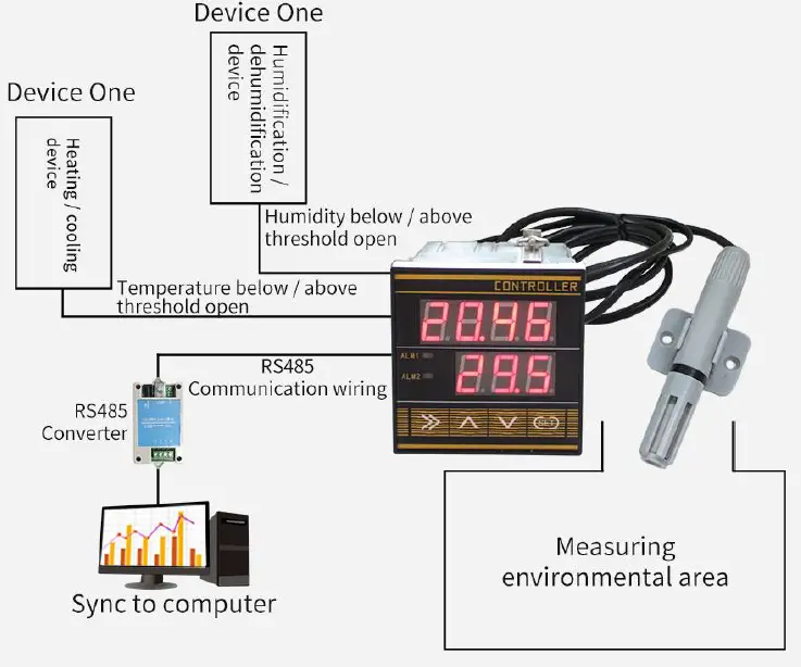
How to use?
APPLICATION OF INTELLIGENT CONTROLLER
Example: During monitorin g, if the temperature and humidity exceed / below the th reshold, the sensor will transmit the temperature and humidity data to the contro ller, then the controller will turn off/ on the device according to the preset t hreshold, and the data will be transmitted through the RS485 communication port. Sync to computer

CONTROL METHOD AND PROCESS
Heating and humidification control, cooling and dehumidification control
Mode 1: The action is below the lower threshold
The temperature I humidity terminal is put into use.
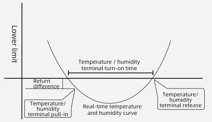
Opening and closing process of temperature and humidity control equipment
Working condition of temperature/ humidity terminal access: measured value <lower limit threshold-return difference
Temperature I humidity terminal release action condition: measured value> lower limit threshold+ return difference value
XAs shown in the figure above, when the measured value is lower than the lower threshold minus the return difference, it will be pulled into the internal temperature/ humidity terminal of the controller and powered on. When the measured value rises to the sum of the upper limit and the return difference, the temperature/ humidity terminal is disconnected. Turn off the device.
Mode 2: Action above the upper threshold
The temperature/ humidity terminal is put into use.
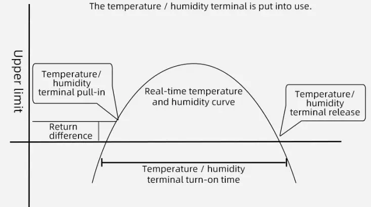
Opening and closing process of temperature and humidity control equipment
Working conditions for temperature and humidity terminal access: measured value> upper threshold+ hysteresis Temperature and humidity terminal release action conditions:
measured value <upper limit threshold-return difference XAs shown in the figure above, when the measured value is higher than the upper threshold plus the return difference, the internal temperature I humidity terminal of the controller will pull in and turn on the device; when the measured value drops to the lower limit threshold minus the return difference, the temperature / humidity terminal Disconnect and turn off the device.
The product uses RS485 MODBUS RTU standard protocol format, all operation or reply commands are hexadecimal data. The default device address is 1 wh en the device is shipped, the default baud rate is 9600, 8, n, 1
- Read Data (Function id 0x03)
Inquiry frame (hexadecimal), sending example: Query 1# device 1 data, the host computer sends the command:01 03 00 00 00 02 C4 0B .Device ID Function id Start Address Data Length CRC16 01 03 00 00 00 02 C4 0B For the correct query frame, the device will respond with data:01 03 04 00 7A 00 00 DB EA , the response format is parsed as follows:
Device ID Function id Data Length Data 1 Data 2 Check Code 01 03 04 00 79 00 7A DB EA Data Description: The data in the command is hexadecimal. Take data 1 as an example. 00 79 is converted to a decimal value of 121. If the data magnification is 100, the actual value is 121/100=1.21. Others and so o n.
- Data Address Table
Address Start Address Description Data type Value range 40001 00 00 temperature Read Only 0~65535 40002 00 01 humidity Read Only 0~65535 40101 00 64 model code read/write 0~65535 40102 00 65 total points read/write 1~20 40103 00 66 Device ID read/write 1~249 40104 00 67 baud rate read/write 0~6 40105 00 68 mode read/write 1~4 40106 00 69 protocol read/write 1~10 - read and modify device address
- Read or query device address
If you don’t know the current device address and there is only one device on th e bus, you can use the command FA 03 00 64 00 02 90 5F Query device address.Device ID Function id Start Address Data Length CRC16 FA 03 00 64 00 02 90 5F FA is 250 for the general address. When you don’t know the address, you can use 250 to get the real device address, 00 64 is the device model register.
For the correct query command, the device will respond, for example the response data is: 01 03 02 07 12 3A 79, the format of which is as shown in the following table:Device ID Function id Start Address Model Code CRC16 01 03 02 55 3C 00 01 3A 79 Response should be in the data, the first byte 01 indicates that the real address of the current device is, 55 3C converted to decimal 20182 indicates that the current device main model is 21820, the l ast two bytes 00 01 Indicates that the device has a status quantity.
- Change device address
For example, if the current device address is 1, we want to change to 02, the command is:01 06 00 66 00 02 E8 14 .Device ID Function id Start Address Destination CRC16 01 06 00 66 00 02 E8 14 After the change is successful, the device will return information: 02 06 00 66 00 02 E8 27 , its format is parsed as shown in the following table:
Response should be in the data, after the modification is successful, the first byte is the new device address. After the general device address is changed, it will take effect immediately. At this time, the user needs to cha nge the query command of the software at the same time.
- Read or query device address
- Read and Modify Baud Rate
- Read baud rate
The device default factory baud rate is 9600. If you need to change it, you can change it according to the following table and the corresponding communication protocol. For example, read the current device’s baud rate ID, the command is:01 03 00 67 00 01 35 D5 , its format is parsed as follows.Device ID Function id Start Address Data Length CRC16 01 03 00 67 00 01 35 D5 Read the baud rate encoding of the current device. Baud rate encoding: 1 is 2400; 2 is 4800; 3 is 9600; 4 is 19200; 5 is 38400; 6 is 115200.
For the correct query command, the device will respond, for example the response data is: 01 03 02 00 03 F8 45, the format of which is as shown in the following table:Device ID Function id Data Length Rate ID CRC16 01 03 02 00 03 F8 45 coded according to baud rate, 03 is 9600, ie the current device has a baud rate of 9600.
- Change the baud rate
For example, changing the baud rate from 9600 to 38400, ie changing the code from 3 to 5, the command is: 01 06 00 67 00 05 F8 16 01 03 00 66 00 01 64 15 .Device ID Function id Start Address Target Baud Rate CRC16 01 03 00 66 00 01 64 15 Change the baud rate from 9600 to 38400, changing the code from 3 to 5. The new baud rate will take effect immediately, at which point the device will lose its response and the baud rate of the device should be queried accordingly. Modified.
- Read baud rate
- Read Correction Value
- Read Correction Value
When there is an error between the data and the reference standard, we can reduce the display error by adjusting the correction value. The correction difference can be modified to be plus or minus 1000, t hat is, the value range is 0 1000 or 64535 65535. For example, when the display value is too small, we can correct it by adding 100. The command is: 01 03 00 6B 00 01 F5 D6 . In the command 100 is hex 0x64 If you need to reduce, you can set a negative val ue, such as 100, corresponding to the hexadecimal value of
FF 9C, which is calculated as 100 65535=65435, and then converted to hexadecimal to 0x FF 9C. The correction value starts from 00 6B. We take the first parameter as an example. The correction valu e is read and modified in the same way for multiple parameters.Device ID Function id Start Address Data Length CRC16 01 03 00 6B 00 01 F5 D6 For the correct query command, the device will respond, for example the response data is: 01 03 02 00 64 B9 AF, the format of which is as shown in the following table:
Device ID Function id Data Length Data value CRC16 01 03 02 00 64 B9 AF In the response data, the first byte 01 indicates the real address of the current device, and 00 6B is the first state quantity correction value register. If the device has multiple parameters, other parameters operate in this way. The same, the general temperature, humidity have this parameter, the light generally does not have this item.
- Change correction value
For example, the current state quantity is too small, we want to add 1 to its true value, and the current value plus 100 correction operation command is:01 06 00 6B 00 64 F9 FD .Device ID Function id Start Address Destination CRC16 01 06 00 6B 00 64 F9 FD After the operation is successful, the device will return information: 01 06 00 6B 00 64 F9 FD, the parameters take effect immediately after successful change.
- Read Correction Value
Disclaimer
This document provides all information about the product, d oes not grant any license to intellectual property, does not express or imply, and prohibits any other means of granting any intellectual property rights, such as the statement of sales terms and conditions of this product, other issues. No liability is as sumed. Furthermore, our company makes no warranties, express or implied, regarding the sale and use of this product, including the suitability for the specific use of the product, the marketability or the infringement liability for any patent, copyright or other intellectual property rights, etc. Product specifications and product descriptions may be modified at any time without notice.
Contact Us
Company: Shanghai Sonbest Industrial Co., Ltd
Address:Building 8,No.215 North east ro ad,Baoshan District,Shanghai,China
Web: http://www.sonbest.com
Web: http://www.sonbus.com
SKYPE: soobuu
Email: [email protected]
Tel: 86 021 51083595 / 66862055 / 66862075 / 66861077


