
SUPER VAC 724BCG-H Aircraft Brake Cooling Fans
DANGER
PERSONAL RESPONSIBILITY CODE
The member companies of FEMSA that provide emergency response equipment and services want responders to know and understand the following:
- Firefighting and Emergency Response are inherently dangerous activities requiring proper training in their hazards and the use of extreme caution at all times.
- It is your responsibility to read and understand any user’s instructions, including purpose and limitations, provided with any piece of equipment you may be called upon to use.
- It is your responsibility to know that you have been properly trained in Firefighting and/or Emergency Response and in the use, precautions, and care of any equipment you may be called upon to use.
- It is your responsibility to be in proper physical condition and to maintain the personal skill level required to operate any equipment you may be called upon to use.
- It is your responsibility to know that your equipment is in operable condition and has been maintained in accordance with the manufacturer’s instructions.
- Failure to follow these guidelines may result in death, burns or other severe injury.
Fire and Emergency Manufacturers and Services Association, Inc. P.O. Box 147, Lynnfield, MA 01940 www.FEMSA.org
I Copyright 2006 FEMSA. All Rights Reserved I
USER GUIDE
This manual covers the description, cautions, operation, and maintenance of the Super Vac 724BCG-H. Read this manual before operating the fan.
Save this guide for future reference.
Breakage or Damage During Shipment
- The transportation company is fully responsible for all shipping damage and will resolve problems promptly if you handle it correctly. Please read these instructions carefully.
- Examine the contents of all shipping cases. If you find any damage, call your transportation agent at once and have them make a description on the freight or express bill describing the damage and the number of pieces. Then write us and we will send you the original bill of lading. Get a claim blank from the express or truck company. Fill the claim form out. Attach the claim blank to the original bill of lading together with a copy of our invoice. Attach a memo on which you show the value of the damaged goods. Mail or hand these papers to your local transportation agent. They will process your claim with reasonable promptness.
- Please note, we cannot and will not enter claims for damages. If we filed claim here, it would be sent to your local freight agent for verification and investigation. This time can be saved by your filing the claim directly. Every consignee is on the ground floor and in contact with the local agent who inspects the damaged goods, and thus, each claim can be given individual attention.
- Since our goods are packed to comply with the regulations of all railroad, truck, and express companies, we cannot allow deduction from any invoice because of any damage, however, be sure to file your claim promptly. Our goods are sold F.O.B. factory. We take receipt from the transportation company certifying that the goods were delivered to them in good order, and our responsibility ceases.
- It is seldom that any breakage or damage occurs in any of our shipments, and in no case will the customer be out any expense if they follow the above instructions.
- Be sure to keep all damaged goods subject to examination of the truck or express company inspector, who may call on you some time later. These damaged goods, of course, will belong to them, and they will inform you what to do with them. If you dispose of these damaged goods, your claim may not be paid.
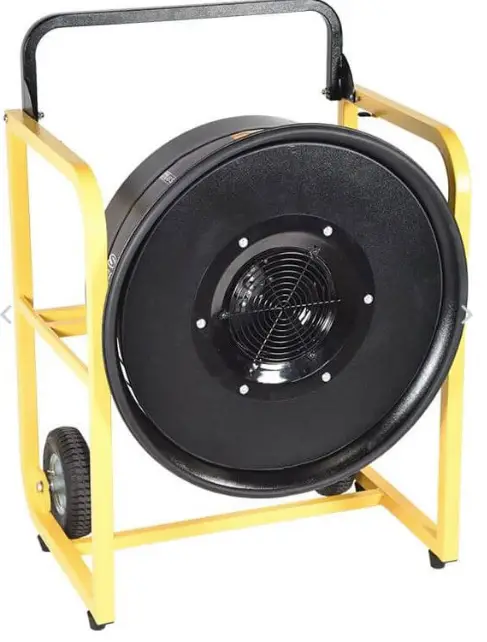
General Description and Specifications
Super Vac ventilators are specifically designed to provide a convenient and portable source of air.
This ventilator is designed for high powered air movement.
This document is designed to function as a quick start guide and not an in-depth comprehensive instructional manual. Please read all accompanying documents shipped with your ventilator. Due to the many features of gasoline powered equipment thorough familiarity with the engine operating controls is essential to assure safe and trouble free operation.
Product Safety Precautions
- Do not use the ventilator for purposes other than its’ intended use.
- Wear eye and ear protection when operating the ventilator.
- Never operate ventilator while fatigued.
- Do not disassemble or modify the ventilator in any way. Doing so may lead to mechanical failure or personal injury.
- Do not wear loose clothing that could become entangled in the operating ventilator.
- Never permit anyone to operate ventilator without proper instruction.
- Do not operate ventilator without proper inlet or outlet guards in place. If guards are missing or damaged, contact factory for replacements.
- Do not place fingers or other foreign objects through inlet or outlet guards. Should a foreign object enter the ventilator, immediately stop engine. Be certain all mechanical motion has stopped. Disconnect spark plug wire from spark plug and keep it away from spark plug before removing foreign object.
- Do not use with any fuel supply source other than the provided fuel tank.
- Engine exhaust gas contains poisonous carbon monoxide. Avoid inhalation of exhaust gas. Never run the engine in a closed or confined area.
- Do not place or operate ventilator on unsteady tables, slanted surfaces or other unstable surfaces. Never use this ventilator in any explosive environment.
- Never use this ventilator in any explosive environment.
- Do not use chock blocks to increase the angle of the ventilator, severe injury could occur.
Before Operating Ventilator
- Engine is shipped without oil. With engine in a level position, remove oil fill plug and dipstick. Fill to outer edge of the oil filler hole with the recommended oil. See page 28 of the HONDA ENGINE Owner’s Manual for oil viscosity recommendations and capacity.
- Always operate this ventilator with unleaded gasoline having a pump octane rating of 86 or higher.
- A complete inspection of the ventilator should be made prior to operation.
- Check all threaded fasteners for proper tightness.
- Inspect inlet and outlet guards for damage or missing pieces. Replace damaged or missing guards before operating ventilator.
Operation
- Check ventilator inlet and outlet guards for obstructions. Check and remove from immediate surrounding area any objects that could be drawn into the ventilator intake.
- Check the engine oil level, running the engine with a low oil level can cause engine damage. See the HONDA ENGINE Owner’s Manual.
- Check the engine air cleaner. A dirty filter will reduce engine performance.
- Check the fuel level. Do not overfill. Starting with no more than a 3/4 full tank will help reduce operating interruptions for refueling and avoid fuel spillage when engine is tilted.
- Place ventilator in desired location before starting.
- Refer to the HONDA ENGINE Owner’s Manual for additional information showing locations of engine control features and positions.
- This engine is equipped with and Oil Alert System which is designed to prevent engine damage caused by an insufficient amount of oil in the crankcase. Before the engine can fall below a safe limit, the Oil Alert System will automatically stop the engine (the engine switch will remain in the ON position). The Oil Alert System is sensitive to the engine being operated at an incline.
Starting the Engine
- Move the fuel lever to the ON position.
- If engine is cold, move choke lever to the CLOSED position.
- Move throttle lever to 1/3 of the way toward the FAST position.
- Turn the engine switch to the ON position.
- Pull the starter grip lightly until resistance is felt, then pull briskly. Do not let the starter grip return by releasing grip. This can lead to starter cord breakage. Return starter grip gently to the recoiled position.

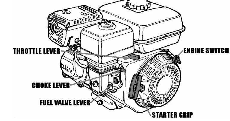
Stopping the Engine
- Move throttle lever to the SLOW position.
- Turn engine switch to the OFF position.
- Turn the fuel valve lever to the OFF position.
Maintenance and Repair
- Maintenance should only be performed by experienced and trained personnel.
- Be sure the ventilator blade has come to a complete stop before performing any maintenance or repair.
- Disconnect spark plug wire from spark plug and keep it away from spark plug.
- The ventilator blade should be specially checked for build-up of material or dirt which may cause an imbalance. Excessive imbalance can lead to accelerated wear on engine bearings and vibration. Remove ventilator guards. Clean blade and inside housing with mild detergent and water. Do not use abrasives, sharp instruments or caustic solvents that may scratch or damage the aluminum alloy blade.
Schedule of Maintenance
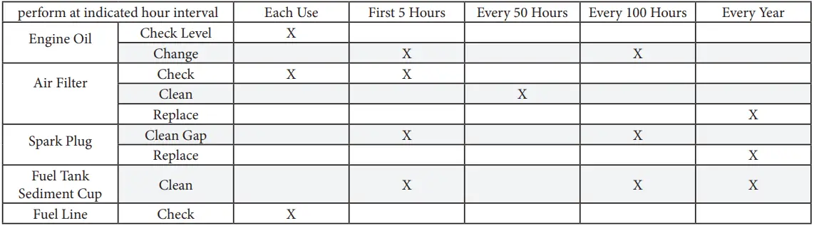
See parts list for replacement part numbers.
Troubleshooting
Common causes of engine overheating:
- Insufficient unobstructed distance on exhaust side of ventilator.
- Incorrect octane fuel – too low octane
| ENGINE WILL NOT START | Possible Cause | Correction |
| Check Control Positions | Fuel Valve OFF | Move Lever to ON |
| Choke is OFF | Set choke to FULL on (Unless engine is warm) | |
| Throttle control is on STOP | Move the throttle control to SLOW | |
| Oil Alert System | Engine oil is low or engine is being operated on too steep an incline. | |
| Check Fuel | Out of fuel | Refuel |
| Deteriorated fuel | Drain fuel tank and carburetor. Refuel with fresh gasoline. | |
| Contamination in fuel tank blocking fuel line | Drain fuel tank and carburetor. Refuel with fresh gasoline. | |
| Remove and Inspect Spark Plug | Spark plug faulty, fouled, or improper gapped | Clean, gap, or replace spark plug. |
Warranty
Super Vacuum Manufacturing Company warrants that the equipment is free from defects in materials and workmanship when used and operated for a period of five years. The responsibility of Super Vacuum Manufacturing Company under this limited warranty is limited to the repair and replacement of any parts which are found defective and which are returned to Super Vacuum Manufacturing Company at 3842 Redman Dr, Fort Collins, CO 80524 with transportation charges prepaid (C.O.D. shipments will not be accepted).
Prior to returning defective parts to SUPER VACUUM MANUFACTURING COMPANY, the original purchaser shall make a claim in writing to SUPER VACUUM MANUFACTURING COMPANY at the above address indicating the model number and type of defect. No parts or equipment will be received by SUPER VACUUM MANUFACTURING COMPANY for repair or replacement under this warranty without specific written authority from it in advance.
Any parts damaged by improper installation, overloading, abuse or accident of any type or cause are not covered by this warranty.
All equipment manufactured by us is pre-run and tested before leaving our plant, and is shipped in good working order and condition. We therefore extend to the original purchasers the following Limited Warranty for the period of five years from the original date of purchase:
- This warranty does not apply to defects caused by accident, misuse, neglect, or wear and tear, nor can we be held responsible for incidental and consequential expense and loss, nor does this warranty apply to equipment where alterations have been executed without our knowledge or consent. These conditions are readily discernible when the equipment is returned to us for inspection.
- On all component parts not manufactured by SUPER VACUUM MANUFACTURING COMPANY, their warranty is to the extent that the manufacturer of such component warrants them to SUPER VACUUM MANUFACTURING COMPANY, if at all. Look in your local business phone directory for the nearest repair station for the brand of parts you have or write to us for the address.
- If equipment received is found to have been damaged in transit, a claim should be made against the carrier within three days, as we assume no responsibility for such damage.
- Any service other than our Authorized Service voids this warranty.
- This warranty is in lieu of and is intended to exclude all other warranties, express or implied, oral or written, including any warranties of MERCHANTABILITY or FITNESS for a particular purpose.
Contact Information
For parts or service information, contact:
Super Vacuum Manufacturing Company, Inc.
3842 Redman Dr.
Fort Collins, CO 80524
- Phone: 800-525-5224, 970-297-7100
- Fax: 970-297-7099
- Email : [email protected]
- Internet: www.supervac.com
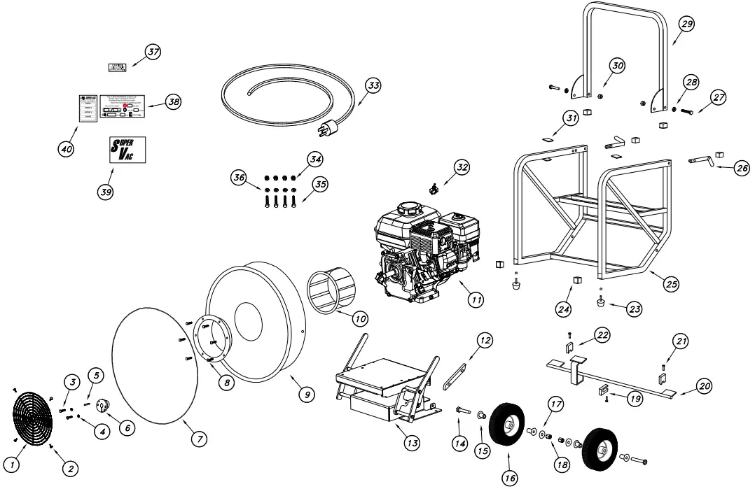
Parts List
| 1 | 012-14143 | 1 | GUARD 724BCS FRONT-PAINTED |
| 2 | 035-11125 | 4 | RIVIT, BLIND, 6-6, SS |
| 3 | 032-10745 | 2 | 1/4 – 20 X 1” HEX CS ZINC |
| 4 | 032-10754 | 2 | 1/4” LOCK WASHER ZINC |
| 5 | 008-10193 | 1 | KEYSTOCK 3/16” X 1 3/8” SQUARE |
| 6 | 008-14145 | 1 | BUSHING BLADE MAUREY HQ X 5/8” |
| 7 | 041-11489 | 1 | EDGE, TRIM SEAL, 3/4 BULB |
| 8 | 003-14150 | 1 | BLADE, INLET CONE, PB831 #C-TO-ICP280 |
| 032-10726 | 6 | SCREW, 1/4-20 X 3/4, PHILLIPS RH, ZINC | |
| 032-10752 | 6 | WASHER, 1/4, FLAT, ZINC | |
| 032-10754 | 6 | WASHER, 1/4, INTERNAL STAR, ZINC | |
| 9 | 018-14028 | 1 | SHROUD, 724BCS, W/GUARD, PAINTED |
| 10 | 003-14149 | 1 | BLADE, PROPELLER, #C-T2-TAL280-1R PB831 |
| 11 | 023-10512 | 1 | ENGINE. 4HP. HONDA 4-CYCLE GX 120KIQX2 |
| 12 | 019-10466 | 1 | 724 BC, SHROUD SUPPORT, BRACKET |
| 13 | 018-15050 | 1 | LIFT MECHANISM |
| 14 | 032-14565 | 2 | 3/8-16 X 4 1/2″ SOCKET BUTTON HEAD ZINC |
| 15 | 005-10136 | 4 | BUSHING REDUCER 3/4” X 1/2” |
| 16 | 008-13373 | 2 | WHEEL PNEUMATIC DW414 3″ HUB CENTER |
| 17 | 032-11129 | 2 | 3/8” FLAT WASHER USS ZINC |
| 18 | 032-11133 | 2 | 3/8-16 NYLOK HEX NUT ZINC |
| 19 | 008-14622 | 1 | VENTILATOR BRAKE MOUNT 1 |
| 20 | 008-14631 | 1 | 724, BRAKE BAR, FINISHED |
| 21 | 032-10725 | 3 | 1/4-20 X 5/8 PHIL RH MS |
| 22 | 008-14623 | 2 | VENTILATOR BRAKE MOUNT 2 |
| 23 | 024-13473 | 2 | FEET RUBBER CONE SHAPE VBM-4002 |
| 032-13052 | 2 | 5/16-24 NYLOK HEX NUT ZINC | |
| 24 | 008-10189 | 6 | PLUG FINISHING SQ RIBBED, BLACK 1” |
| 25 | 018-15019 | 1 | TUBE FRAME 24” PAINTED, BCS |
| 26 | 008-10192 | 2 | SPRING A-180-S VALCO |
| 27 | 032-14564 | 2 | 3/8-16 X 2 1/2” SOCKET BUTTON HEAD CS ZN |
| 28 | 032-11129 | 2 | 3/8” FLAT WASHERUSS ZINC |
| 29 | 019-10461 | 1 | 724 HANDLE PAINTED |
| 30 | 032-11133 | 2 | 3/8-16 NYLOK HEX NUT ZINC |
| 31 | 008-14586 | 2 | STOCK CAP COVER FOR 718 HANDLE TAB |
| 32 | 005-10145 | 1 | SWITCH CA204-73 .1- 1/2 HP |
| 33 | 005-10120 | 1 | CORD 14-3 SO 10′ MOLDED |
| 34 | 032-10790 | 4 | 5/16-18 NYLOK HEX NUT ZINC |
| 35 | 032-10770 | 4 | 5/16-18 X 1 1/2” HEX CS ZINC |
| 36 | 032-10786 | 4 | 5/16” FLAT WASHER ZINC |
| 37 | 025-10544 | 1 | DECAL CAUTION GUARDS REMOVED |
| 38 | 1 | DECAL 724BCG-H YELLOW SAFETY | |
| 39 | 025-13426 | 1 | DECAL SUPER VAC REFLECTIVE |
| 40 | 1 | DECAL 724BCG-H SER# GREY |
Exploded View
Lift Mechanism
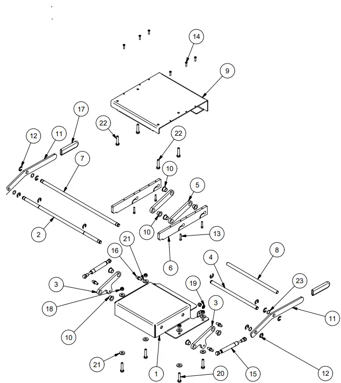
| PARTS LIST | ||||
| ITEM | QTY | PART NUMBER | DESCRIPTION | |
| 1 | 1 | 018-16209 | BASE,TILT, BRAKE COOLER | |
| 2 | 1 | 018-16203 | SHAFT, BOTTOM FRONT, BRAKE COOLER | |
| 3 | 2 | 018-16205 | BRACKET,TILT, BRAKE COOLER | |
| 4 | 1 | 018-16200 | SHAFT,BOTTOM REAR, BRAKE COOLER | |
| 5 | 2 | 018-16204 | BRACKET,TILT, BRAKE COOLER | |
| 6 | 2 | 018-16207 | MOUNT,PIVOT, BRAKE COOLER | |
| 7 | 1 | 018-16202 | SHAFT,TOP FRONT, BRAKE COOLER | |
| 8 | 1 | 018-16201 | SHAFT,TOP REAR | |
| 9 | 1 | 018-16208 | TOP PLATE, TILT, BRAKE COOLER | |
| 10 | 8 | 065-13846 | BUSHING, 5X 75X .03125 THERM. POLYMER | |
| 11 | 2 | 018-16206 | HANDLE,MOUNT, BRAKE COOLER | |
| 12 | 12 | 069-15336 | E-Ring, 5133-50, .044T, SS | |
| 13 | 4 | STD HARDWARE-SHCS-47 | SCREW,SHCS,10-24×1,SS | |
| 14 | 6 | STD HARDWARE-FHMS-85 | SCREW,FHPMS,10-24 UNC x 3/4 in,SS | |
| 15 | 2 | GAS SPRING | GAS SPRING | |
| 16 | 4 | MOUNT | MOUNT, GAS SPRING | |
| 17 | 2 | 008-10211 | CAP,FAN,HANDLE,718 | |
| 18 | 6 | 034-11057 | NUT,NYLOCK, 5/16-18 UNC,SS | |
| 19 | 2 | STD HARDWARE LW39 | WASHER,LOCK,SPRING,REGULAR, 5/16″, SS | |
| 20 | 4 | STD HARDWARE-HHCS-235 | SCREW,HH,5/16-24×1-1/2,SS | |
| 21 | 8 | STD HARDWARE W24 | WASHER,FLAT,USS, 5/16″, SS | |
| 22 | 4 | STD HARDWARE-HHCS-35 | SCREW,HH,5/16-18×1-1/2,SS | |
| 23 | 4 | AS568A-015 | ORING,ID 0.551,SIZE 0.551,AS568A-015 | |


