![]()
User Manual of XRotor Series Controllers for Multi-rotors
HW-SMC905-COMBO-XRotor-X9-MAX-RTF_20210528
XRotor-X11-18S Brushless COMBO
Thank you for purchasing this product! Please read the following statement carefully before use and, once used, it is considered to be an acceptance of all the contents. Please strictly observe and adhere to the manual installation with this product. Unauthorized modification may result in personal injury and product damage. We reserve the rights to update the design and performance of the product without notice.
Introduction
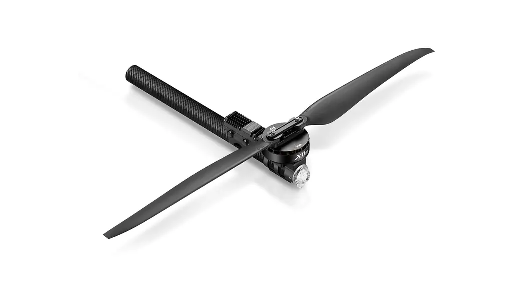
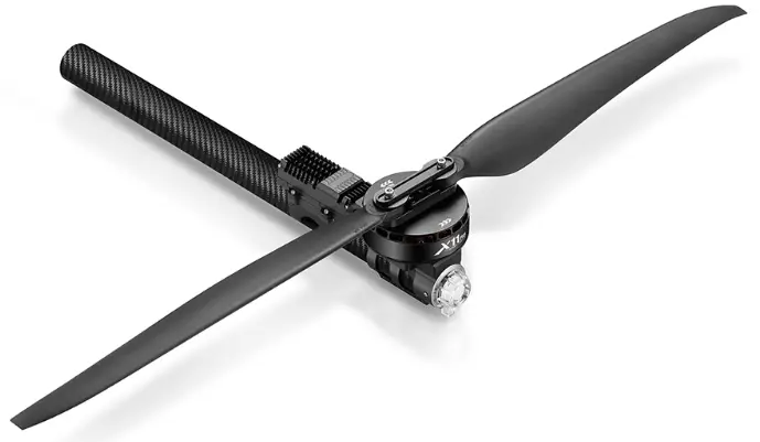
The XRotor-X11-18S brushless COMBO is a plant protection power system that adapts to a single-axis load of 15-18kg. The maximum pulling force of a single-axis is 34kg; it is suitable for 45/50mm carbon fiber tube arms, equipped with IPX6 waterproofing protection and is not afraid of rain Pesticides, salt spray, high temperature, sand and dust, impact resistance, mud and sand resistance. The ESC uses FOC-motor PMSM system algorithm optimization. The system has power-on self-test, power-on voltage abnormal protection, over-current protection, stall protection, etc. Protection function, with real-time data transmission.
Precautions
- Please stay away from crowds, high-voltage lines, obstacles, etc. when using, and be sure to follow safety regulations.
- Do not get close to the high-speed rotating propeller and motor to prevent being cut by the blades.
- Please check whether all parts are in good condition before trial use. If there is any damage, contact the after-sales service for replacement in time.
- Before flying, check whether the screws of the connecting structure are loose and whether the motor is level.
- The X11-18S power system is connected to a circular pipe arm with a pipe diameter of 50mm.
- The color of the power system navigation light is optional. After removing the light housing, you can select the desired color by flipping the dial switch.
- After each operation is completed, the motor can be washed with water, and the motor should be kept clean.
Components of Power System
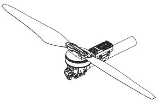
Motor*1 ESC*1 Propeller*1 Motor mount*1 A number of fastening screws LED light set
Installation of Power System
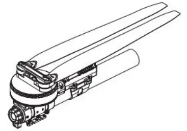
- The entire power system has been assembled at the factory, and the power system can be taken out directly from the package, and installed on the frame of the plant protection aircraft according to the direction of rotation of the motor.
- The yellow, red and green cables are data output and upgrade signal lines (the ESC system can be upgraded), the yellow line is the ground line; the white and black lines are the accelerator signal lines, and the black line is the ground line.
- The data signal line outputs in real time the input and output throttle, motor speed, bus current, phase current, bus voltage, capacitor temperature, MOS tube temperature and other data.
- ESC accelerator is solidified as 1050~1950us。
Specifications
| Suitable for uniaxial load | 15-18kg/rotor |
| Compatible Lipo Battery | 18S(Max61V) |
| Applicable carbon tube | 50 mm |
| Waterproof protection level | IPX6 |
| Maximum pulling force | 34kg |
| Suitable temperature usage | -20℃-50℃ |
| Overall weight. | 2340g |
| Support throttle frequency | 50-500Hz |
ESC:
| Continuous current | 45A(Non-hermetic Ambient Temperature≤60℃) |
| Maximum Current | 150A(Non-hermeticAmbient Temperature ≤60℃) |
| Curing the throttle | 1050-1950us |
| Motor: | |
| Model | 11115 |
| KV | 75rpm/v |
| Propeller: | |
| Name | 41135 |
| Signal propeller weight | 139g |
| Support lithium battery | 18S |
| Outer diameter | 120mm |
| Total weight(inc adapter) | 422g |
Parameter of the Power System
| Voltage(V) | Propeller | Throttle(%) | Thrust(g) | Current(A) | Power(W) | Speed(RPM) | Efficiency(g/W) |
| 70V (18S LIPO) | HW 41*13.5Inch Foldable Propeller | 40% | 8760 | 12.4 | 854.8 | 1956 | 10.2 |
| 42% | 9560 | 14.1 | 973.5 | 2044 | 9.8 | ||
| 44% | 10455 | 16.1 | 1113.4 | 2138 | 9.4 | ||
| 46% | 11420 | 18.4 | 1271.7 | 2235 | 9 | ||
| 48% | 12330 | 20.7 | 1427.3 | 2323 | 8.6 | ||
| 50% | 13065 | 22.5 | 1557 | 2391 | 8.4 | ||
| 52% | 14300 | 25.8 | 1782.6 | 2499 | 8 | ||
| 54% | 15300 | 28.5 | 1972.1 | 2583 | 7.8 | ||
| 56% | 16420 | 31.7 | 2191.3 | 2673 | 7.5 | ||
| 58% | 17720 | 35.5 | 2455.5 | 2773 | 7.2 | ||
| 60% | 18730 | 38.6 | 2668.4 | 2848 | 7 | ||
| 62% | 19675 | 41.6 | 2874.3 | 2918 | 6.8 | ||
| 64% | 20785 | 45.2 | 3125.2 | 2998 | 6.7 | ||
| 66% | 22160 | 50 | 3451.4 | 3096 | 6.4 | ||
| 68% | 23030 | 53.1 | 3667.6 | 3158 | 6.3 | ||
| 70% | 23960 | 56.6 | 3908.4 | 3224 | 6.1 | ||
| 72% | 25400 | 62.3 | 4302.9 | 3327 | 5.9 | ||
| 74% | 26670 | 67.7 | 4675.6 | 3418 | 5.7 | ||
| 76% | 27045 | 69.4 | 4790.5 | 3444 | 5.6 | ||
| 78% | 28290 | 75.2 | 5189.7 | 3532 | 5.5 | ||
| 80% | 29655 | 82 | 5661 | 3627 | 5.2 | ||
| 90% | 33230 | 102.7 | 7090.4 | 3842 | 4.7 | ||
| 100% | 34775 | 113.2 | 7809.7 | 3909 | 4.5 |
Protection
- Start protection:
When the power is connected normally, the ESC will first start the self-test. If the self-test is successful, it will run normally after beeping. If the self-test fails, it will not start and the flashing light will warn. - Stall Protection:
When the ESC detects that the motor is locked, the ESC will completely turn off the output and will not restart the motor. At this time, it is necessary to power on again to clear the error and restart the ESC to restore power output. - Current Protection:
When it detects that the instantaneous current abnormality reaches close to 300A, the ESC will restart immediately, and the output will be turned off if the detection times reach abnormality five times in a row, and it will return to normal after the power is turned on again. - Throttle signal loss protection:
When the ESC detects that the throttle remote control signal is lost for more than 0.25 seconds, it will immediately turn off the output to avoid greater losses caused by the continued high-speed rotation of the propeller. After the signal is restored, the ESC will immediately restore the corresponding power output.
Warning tone description
| Symptom | Tone | Possible causes | Possible solutions |
| Motor fails to start after power on | -Beep beep beep” rapid monotone | Throttle is not reset to zero | Push the throttle to the lowest point or recalibrate the throttle point |
| Motor fails to start after power on | “Beep, Beep. Beep’ (1 second for each interval) | No throttle signal input on the receiver throttle channel | Check if transmitter and receiver is normal. Check if wiring of throttle channel is normal |
| The power-on voltage is lower than 18V or higher than 63V | Bee ‘ (1 Bee Beep, p, Beep’ second for each interval) | Battery voltage is too low | Replace with a full-charged battery |
Daily usage
1. Adjust LED light color
Use a tool to take out the M3×8 screws that fasten the lampshade, and set the switch according to the corresponding light color below (factory default green). After the setting is successful, assemble and fasten the lampshade in the original way.
| Dial code on/off 1 | Dial code on/off 2 | Dial code on/off 3 | LED color |
| ON | ON | ON | White |
| ON | OFF | ON | Light blue |
| ON | ON | OFF | Purple |
| ON | OFF | OFF | Blue |
| OFF | ON | ON | Yellow |
| OFF | OFF | ON | Green |
| OFF | ON | OFF | Red |
| OFF | OFF | OFF | LED on/off |
2. Description of light color status
| Select light color before it blinks | Meaning | Solution |
| Continuous single short flash | Over-voltage | Replace the battery (battery below 82V) |
| Continuous 2 short flash | Under-voltage | Replace the battery (battery higher than 18V) |
| Continuous 3 short flash | Over-current | Power on again, and check the motor for foreign objects Contact after sales service |
| Continuous single long flash | Throttle lost | – Check connection between signal line to the flight controller – Check whether the remote controller and flight controller are turned on – Check the resistance of the black and white wires, if there is a short circuit, contact the after-sales service |
| Continuous (Single long flash + Single short flash) | Throttle not reset to zero | This problem occurs during the rotation of the motor. Please check the aircraft battery and circuit. There is a short circuit on the circuit. |
| Continuous (Single long flash + 2 short flash) | MOS overheated (Over 110t ) | Cool down the power system and power on again |
| Continuous (Single long flash + 3 short flashes) | Capacitor overheated ( Over 110t ) | Cool down the power system and power on again |
| Continuous (Single long flash + 4 short flashes) | Trigger stall protection | – Restart after the throttle is reset to zero – Please check if there is any foreign matter in the motor, remove the foreign matter before starting |
| Continuous (2 long flashes) | Short-circuit | Please check whether the motor circuit is intact Contact after sales service |
| Continuous (2 long flashes + single short flash) | Short-circuit | Please check whether the motor is in good condition Contact after sales service |
| Continuous (2 long flashes + 2 short flash) | Short-circuit | Please check whether the motor is in good condition Contact after sales service |
| Continuous (2 long flashes + 3 short flash) | Phase A operational amplifier is abnormal | Re-power on to return to normal Contact after sales service |
| Continuous (2 long flashes + 4 short flash) | Phase B operational amplifier is abnormal | Re-power on to return to normal Contact after sales service |
| Continuous (3 long flashes) | Phase C operational amplifier is abnormal | Re-power on to return to normal Contact after sales service |
3. Abnormal LED alarm during power-on
| LED | Tone | Possible causes | Possible solutions |
| Continuous single short flash( 0.5 second for each interval) | ‘Beep beep beep” rapid monotone(0.5 second for each interval) | Throttle is not reset to zero | Push the throttle to the lowest point or the throttle point |
| LED on | “Beep. Beep. Beep”( 0.5 second for each interval) | The output data and upgrade lines has short-circuited. | Check the yellow. red and green cables |
| Continuous single shod flash (1 second for each interval) | No beep | Phase is abnormal. | Contact after sales service |
4. Replacing the propeller
- Use the appropriate tools to take out the two propeller fastening screws in and replace them with intact propellers. If you need to replace the propeller clips, continue to take out the fastening screws and replace the whole set of propeller clips and propellers.
- Installing the propeller clip blades
– Firstly, install the bottom cover on the motor, followed by the propeller blades, propeller gaskets, upper cover (propeller clips) and the final screws in order; pay attention to the installation of the propeller screws
After clamping, the propeller should rotate freely, and make sure that the propeller clamp and the motor fastening screw are tightened and screw glue is used at the same time.
5. Firmware upgrade
Use the Hobbywing DataLink V2 box to upgrade the program, and ESC not supported DataLink V1 box. Upgrade step according to the DataLink V2 box user of manual.
6. ESC work data checking
- Use the Hobbywing DataLink box to check ESC work data. According to the DataLink V2 box user of manual.
- ESC work data by serial communication. Flight control needs to support Haoying protocol to obtain ESC data.
After-sale maintenance
In the event that the equipment of the power system is damaged, please contact Hobbywing after-sales customer service immediately.
Under the premise of not affecting the performance, make sure that you can use the Hobbywing power system kit accessories for replacement after contacting the customer service. Users are prohibited from configuring accessories by themselves (such as screws, paddle clips, propellers) for replacement.


