![]()
Bettis RTS Ball Screw Linear Drives
Instruction Manual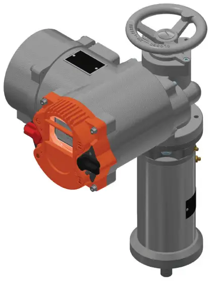
Bettis RTS
Ball Screw Linear Drives
Installation, Operation, and Maintenance Manual
VCIOM-15429-EN Rev. 1 July 2021
Section 1: General
Type ball screw linear drive units are offered in different variants, see Table 1. These are mounted together with electric open/close or modulating actuators, of the series CM, on valves that require a linear positioning movement. These linear units convert the torque output from the actuator into an axial force through a ball screw drive. Not only is a higher control accuracy allowed, but also a longer lifetime is provided with the use of a ball screw drive. The combination of the actuator and linear unit is based on the required thrust and the necessary stroke.
Table 1. Technical Data Linear Units
| Type | Actuator | Output Flange | Output Stroke Thread | Pitch | Factor (NmikN) | Weight (kg) | |
| LK50 | CM03 | GO/F10 | 50 mm | M20x1.5 mm | 5 mm/rev | 1. | 12. |
| LK100 | CM03 | GO/F10 | 100 mm | M20x1.5 mm | 5 mm/rev | 1. | 15.0 |
| LK120 | CM06 | GO/F10 | 120 mm | M20x1.5 mm | 5 mm/rev | 1. | 19. |
| CM06 | G1/2 F14 | 120 mm | M36x3 mm | 5 mmirev | 1. | 24. | |
Section 2: Structure
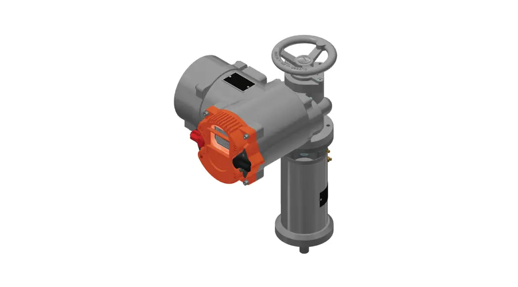
Figure 1 shows e.g. a CM-32 actuator with a mounted LK100 linear unit. The linear unit itself consists essentially of a solid cast housing, a mounted spindle nut, and a nonrotating spindle, see Figure 2. To prevent contamination by dusty ambient air and to ensure mechanical protection, the linear unit is completely sealed with O-Rings at the output.
Figure 1 CM-32-Actuator with Mounted LK100 Linear Unit
Figure 2 shows the exploded drawing of the linear unit. The parts are listed in Table 2.
Figure 2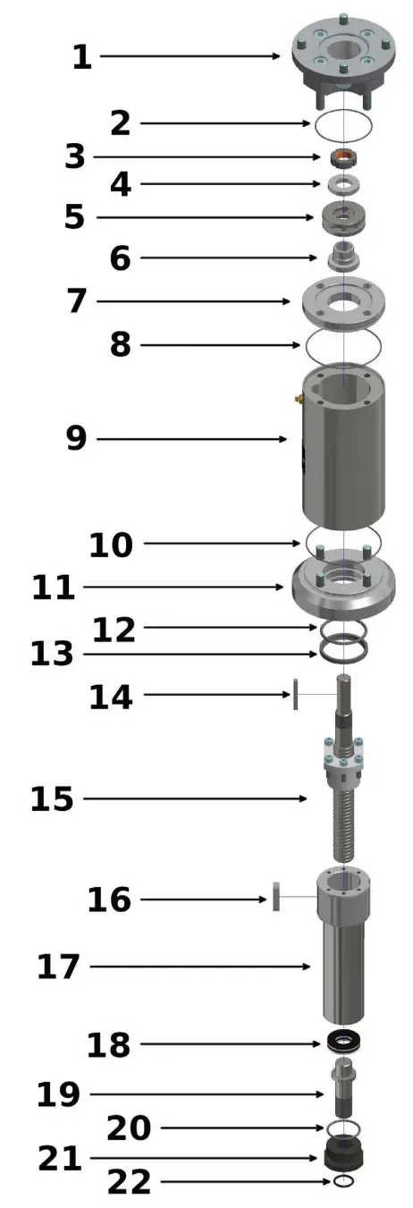
Table 2. Parts List of the Linear Unit
| Part Number | Description |
| 1 | Output flange |
| 2 | O-Ring |
| 3 | Groove nut |
| 4 | Bearing plate |
| 5 | Axial deep groove ball bearing |
| 6 | Bearing ring |
| 7 | Intermediate flange |
| 8 | O-Ring |
| 9 | Housing tube |
| 10 | O-Ring |
| 11 | Base flange |
| 12 | O-Ring |
| 13 | Wiper |
| 14 | Feather key |
| 15 | Ball screw spindle |
| 16 | Feather key |
| 17 | Coupling and output shaft |
| 18 | Cup spring |
| 19 | Spindle pin |
| 20 | O-Ring |
| 21 | Spindle pin ring nut |
| 22 | O-Ring |
Section 3: Packaging, Transport, and Storage
See chapter “Packaging, Transport and Storage” in the standard user manual.
Section 4: Assembly and Disassembly of Linear Units on Valves
In the following two subsections, the procedures for assembly and disassembly of linear units on valves are explained step by step.
4.1 Security and Assembly Instructions
![]() WARNING
WARNING
The device may only be mounted and commissioned by qualified personnel! Qualified personnel within the meaning of this operating manual are persons who are familiar, with the assembly, commissioning, and operation of this product, and have the required appropriate qualifications for this activity.![]() WARNING
WARNING
For assembly and disassembly of the linear unit, the pipes where the valve is installed must be depressurized. If the actuator is removed from the linear unit, the position of the valve stem won’t be fixed anymore and will be lost due to the linear unit’s non-self-locking property.![]() WARNING
WARNING
The linear unit has end stops on both end positions. Do not move against the end stops in electrical operation. The end limits of the actuator must be set accordingly. Never bring the valve cone with excessive force in the CLOSED position. This can damage the high-quality sealing edges.
Section 4: Assembly and Disassembly
4.2 Assembly
- Check that the actuator flange, the linear unit flanges, and the valve flange match.
- Thoroughly clean screw-on surfaces and bare parts on the actuator, linear unit, and valve.
- Lightly grease the connections of the actuator, the linear unit, and the valve.
- Grease the spindle of the linear unit.
- Move the valve cone in the CLOSED position.
- Turn the spindle nut until the linear unit is in a central position.
- Mount the linear unit on the valve and tighten the screws crosswise. The coupling between the linear unit and the valve will be connected later.
- Mount the actuator on the linear unit and tighten the screws crosswise.
- Extend the spindle by rotating the handwheel until the coupling of the linear unit and the valve fit together.
- Connect the coupling between the linear unit and the valve.
- Use the handwheel to move the linear unit to a center position, to prevent accidental damage to the valve during start-up.
Disassembly
- If the valve is fully closed, move the valve cone to about ten percent OPEN position.
- Loosen the screws between the output flange of the actuator and the linear unit and dismount the actuator.
- Open the spindle coupling between the linear unit and the valve.
- Loosen the screws between the output flange of the linear unit and the valve.
- Dismount the linear unit from the valve.
Section 5: Commissioning
See chapter Commissioning in the standard user manual.
Section 6: Maintenance
Pay attention to increased running noises, that occur on them, and grease the two lubrication nipples of the linear unit to lubricate the bearings and the spindle guidance.
Regularly check the fixing screws between the actuator, the linear unit, and the valve for firm hold, if necessary tighten them with the torques specified in chapter “Installation Instructions” of the standard user manual.
6.1 Moving Interval
The linear unit should be actuated at least every 3 months.
6.2 Greasing Interval
Every 6 months the linear unit should be regreased via the greasing nipples.
Section 7: Lubricant Recommendation
Lubricating grease DIN 51825-K(P) R -40
i.e. Water repellent complex grease based on Al-soap with high resistance to acids and alkalis:
Ambient temperature: -40 bis +85 °C
Worked penetration 0.1 mm: 310 – 340
Dripping point: ca. 260 °C
NLGI-Class: 1
Acid-free, not or only slightly reactive with water
World Area Configuration Centers (WACC) offer sales support, service, inventory, and commissioning to our global customers.
Choose the WACC or sales office nearest you:
NORTH & SOUTH AMERICA
19200 Northwest Freeway
Houston TX 77065
USA
T +1 281 477 4100
Av. Hollingsworth
325 Iporanga Sorocaba
SP 18087-105
Brazil
T +55 15 3413 8888
ASIA PACIFIC
No. 9 Gul Road
#01-02 Singapore 629361
T +65 6777 8211
No. 1 Lai Yuan Road
Wuqing Development Area
Tianjin 301700
P. R. China
T +86 22 8212 3300
MIDDLE EAST & AFRICA
P. O. Box 17033
Jebel Ali Free Zone
Dubai
T +971 4 811 8100
P. O. Box 10305
Jubail 31961
Saudi Arabia
T +966 3 340 8650
24 Angus Crescent
Longmeadow Business Estate EaP.O. Box 6908 Greenstone
1616 Modderfontein Extension 5
South Africa
T +27 11 451 3700
EUROPE
Holland Fasor 6
Székesfehérvár 8000
Hungary
T +36 22 53 09 50
Strada Biffi 165
29017 Fiorenzuola d’Arda (PC)
Italy
T +39 0523 944 411
For a complete list of sales and manufacturing sites, please visit www.emerson.com/actuationtechnologieslocations or contact us at i[email protected]
www.emerson.com/bettis
VCIOM-15429-EN ©2021 Emerson. All rights reserved.
The Emerson logo is a trademark and service mark of Emerson Electric Co. BettisTM is a mark of one of the Emerson family of companies. All other marks are property of their respective owners.
The contents of this publication are presented for information purposes only, and while effort has been made to ensure their accuracy, they are not to be construed as warranties or guarantees, express or implied, regarding the products or services described herein or their use or applicability. All sales are governed by our terms and conditions, which are available on request. We reserve the right to modify or improve the designs or specifications of our products at any time without notice.![]()


