SHURE MX400SMP Microflex Surface Mount Preamp
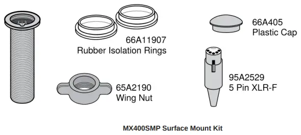
IN THE BOX
Installation
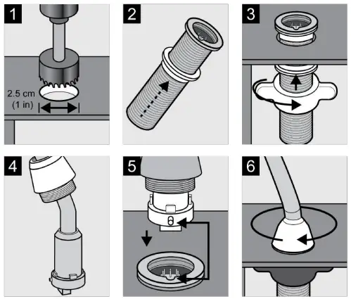
Note: Over tightening the wing nut reduces shock isolation.
Caution: To prevent bending pins, line up key with notch and seat connector fully before twisting to lock.
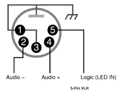
MX400SMP Pin Assignments
DIP Switches
Set DIP Switch 1 up to engage the low cut filter, which attenuates frequencies by 6 dB per octave below 150 Hz.
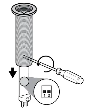
| Switch | Down (default) | Up |
| 1 | Full frequency response | Low cut filter |
| 2 | LED steady | LED flashes |
LED Logic
- To operate the LED indicator, use the included 5-pin XLR connector to wire the microphone to an automatic mixer or other logic device.
- Note: Connect the LED IN to the gate output to illuminate the LED when the channel is gated on.
- Do not use the relay ports on Crestron and AMX devices. Use the I/O logic ports instead.
- The LED logic may not function when connecting to devices that do not have internal “pull-up resistor” logic circuits, such as
- Clear One DSP products. External pullup resistor circuits can be added for each microphone. Visit www.shure.com/FAQ for detailed instructions.

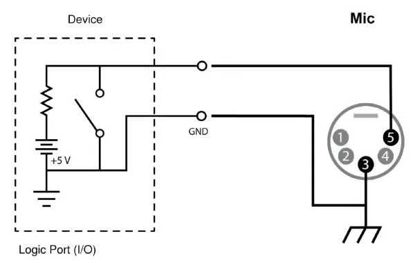
Logic Connection
Connection to device with internal “pull-up resistor” logic circuit
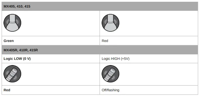
| MX405, 410, 415 | |
| Logic LOW (0 V) | Logic HIGH (+5 V) |
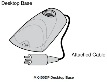
MX400DP Desktop Base
The MX400DP moveable desktop base includes a configurable mute button with logic output.
Installation
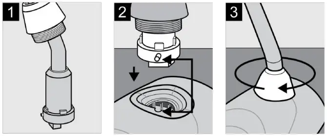
Caution: To prevent bending pins, line up key with notch and seat connector fully before twisting to lock.
Cable
The 20 ft. attached cable is terminated with a 3-pin XLR connector. For logic applications, open the XLR connector to access the three unterminated logic conductors.
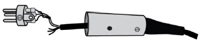
| Wire Color | Function |
| Red | Audio + |
| Black | Audio − |
| White | SWITCH OUT |
| Orange | LED IN |
| Green | Logic Ground |
| Shield | Mic Common Ground |
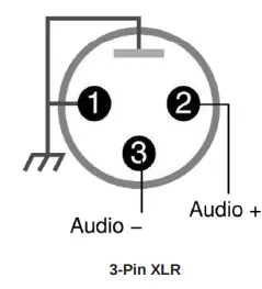
MX400DP Pin Assignments
MX400DP DIP Switches
Caution: Failure to reinstall the setscrew will reduce RF immunity.
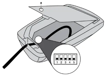
| Switch | Down (default) | Up |
| 1 | Momentary | Toggle |
| 2 | Push-to-Mute | Push-to-Talk |
| 3 | Local Mute | Logic Control |
| Switch | Down (default) | Up |
| 4 | Full Frequency Range | Low Cut Filter (attenuates 6 dB per octave be low 150 Hz) |
| 5 | LED Steady | LED Flashes |
Local Mute Control
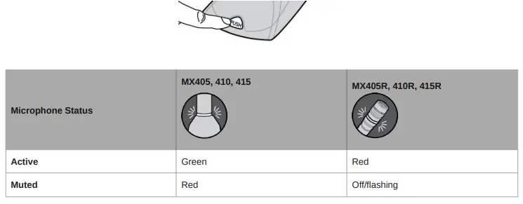
- The microphone ships configured for local (manual) mute control (DIP Switch 3 down). In this mode, the PUSH button on the microphone mutes the audio signal at the microphone. Audio is not sent to the audio outputs when muted.
- In this configuration, the LED color reflects the microphone state, as controlled by the user with the PUSH button.

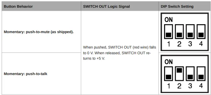
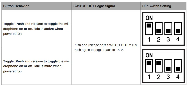
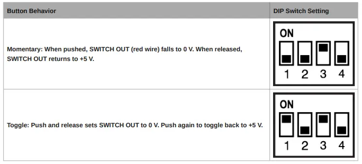
Button Configuration
For local mute control operation, use DIP Switches 1 and 2 to configure the button behavior.
Logic Mute Control (Automatic Mixing)
- Set DIP Switch 3 up to configure the microphone for logic control applications where audio from the microphone is muted by an external device, such as an automatic mixer. In this mode, the local mute function of the PUSH button is bypassed (the microphone always sends audio) and the LED does not respond directly from pushing the button.
- As required by the installation specifications, wire the SWITCH OUT conductor in the microphone cable to the automatic mixer or other TTL logic device. When the talker presses the button on the microphone, it changes the voltage level at the SWITCH OUT conductor, which signals the device to mute audio for that channel or perform some other function.
- To control the LED on the microphone, wire the LED IN conductor to the gate output on the automatic mixer (or any TTL logic device).
Button Configuration
For logic control operation, DIP Switch 1 determines the button behavior (DIP Switch 2 has no effect).
Controlling the LED Using Logic LED IN
When configured for logic mute control, connect the LED IN conductors to an external switch, relay, or a TTL gate (gate out) on
an automatic mixer. The MX400DB contains an internal pull-up resistor circuit.
- The LED illuminates green/red when the MX396 LED IN is grounded (orange wire connected to the green wire).
- The LED illuminates red/off when LED IN is lifted (orange wire is NOT connected to the green wire).
Cable
MX400DP
6.1 m (20 ft) attached cable with shielded audio pair terminated at a 3pin male XLR and three unterminated conductors for logic control
Environmental Conditions
| Operating Temperature | –18–57°C (0–135°F) |
| Storage Temperature | –29–74°C (–20–165°F) |
| Relative Humidity | 0–95% |
Power Requirements
Phantom Power
48-52 V DC, 8.0 mA
| MX400DP | 0.516 kg (1.138 lbs) |
| MX400SMP | 0.125 kg (0.275 lbs) |
Logic Connections
| LED IN | Active low (≤1.0V), TTL compatible. Absolute maximum voltage: 0.7V to 50V. |
| LOGIC OUT | Active low (≤1.0V), sinks up to 20mA, TTL compatible. Absolute maximum voltage: 0.7V to 50V (up to 50V through 3kΩ). |
Mute Switch Attenuation
-50 dB minimum
Output Impedance
170 Ω
Output Configuration
Active Balanced


