NIBE UKV 40 Accumulator Tank
Important information
SAFETY INFORMATION
This manual describes installation and service procedures for implementation by specialists.
The manual must be left with the customer.
This appliance can be used by children aged from 8 years and above and persons with reduced physical, sensory or mental capabilities or lack of experience and knowledge if they have been given supervision or instruction concerning use of the appliance in a safe way and understand the hazards involved. Children shallnot play with the appliance. Cleaning and user maintenance shall not be made by children without supervision.
This is an original manual. It may not be translated without the approval of NIBE. Rights to make any design or technical modifications are reserved. ©NIBE 2023.
SYMBOLS
Explanation of symbols that may be present in this manual.
![]() NOTE
NOTE
This symbol indicates danger to person or machine.
![]() Caution
Caution
This symbol indicates important information about what you should consider when installing or servicing the installation.
MARKING
Explanation of symbols that may be present on the product’s label(s).
GENERAL
UKV 40 is designed and manufactured according sound engineering practice1 in order to ensure safe usage.
1 Pressure Equipment Directive 2014/68/EU Article 4 point 3.
SERIAL NUMBER
The serial number can be found on top of the product.
![]() Caution Always give the product’s serial number when reporting a fault.
Caution Always give the product’s serial number when reporting a fault.
RECOVERY
Leave the disposal of the packaging to the installer who installed the product or to special waste stations. Do not dispose of used products with normal household waste. It must be disposed of at a special waste station or dealer who provides this type of service.
Improper disposal of the product by the user results in administrative penalties in accordance with current legislation.
INSPECTION OF THE INSTALLATION
Current regulations require the heating installation to be inspected before it is commissioned. The inspection must be carried out by a suitably qualified person.
| Description | Notes | Signature | Date | ||||
| Heating medium (page 14) | |||||||
| Shut off valves | |||||||
| Safety valve | |||||||
For the User
MAINTENANCE
The safety valve in the system where the accumulator tank is installed must be inspected regularly (about four times a year) to prevent blockages.
To inspect the valve, open the safety valve manually and check that water flows through the overflow pipe. If this does not happen then the safety valve is defective and must be replaced.
SERVICE
For service, contact the installer. Serial number (PZ3) (14 digits) and installation date should always be stated. Only replacement parts supplied by NIBE may be used.
For the Installer
GENERAL
UKV 40 can be used during external control of the heating system. The heat pump then charges UKV 40 with floating or fixed condensing. The external control function controls the heat distribution from UKV 40 to the consumer.
If the flow to the heating system can be restricted using radiator thermostats, for example, install a UKV 40 as an intermediate tank. This ensures a secure flow for the heat pump.
TRANSPORT
ASSEMBLY
MOUNTING
SUPPLIED COMPONENTS
COMPONENT LOCATION
UKV 40
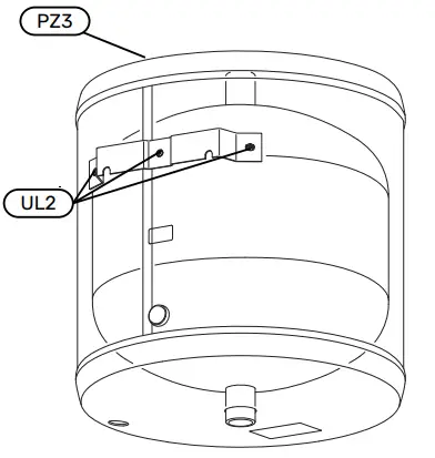
| Designa- tion | Name |
| UL2 | Holes for wall bracket |
| PZ3 | Serial number plate |
INSTALLATION
All connections (including connections or holes that are not used) must be insulated to minimise energy losses.
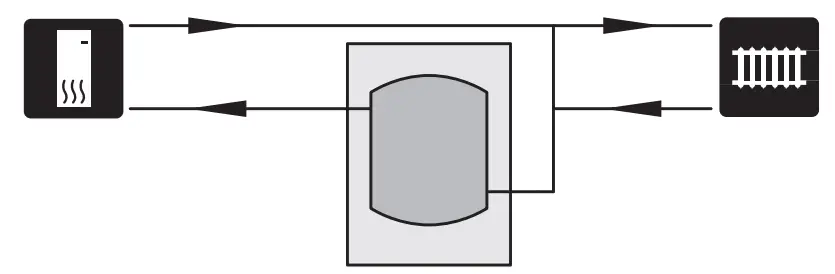
DOCKINGS
![]() NOTE These are outline diagrams. Actual installations must be planned according to applicable standards.
NOTE These are outline diagrams. Actual installations must be planned according to applicable standards.
Volume increase as well as reduction of heat spikes
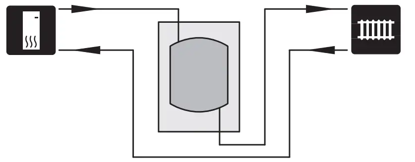
A UKV 40 is installed as a volume increaser in those cases where the system volume in the climate system is below the minimum recommended volume for the heat pump. Volume and flow increaser and reduction in heat spikes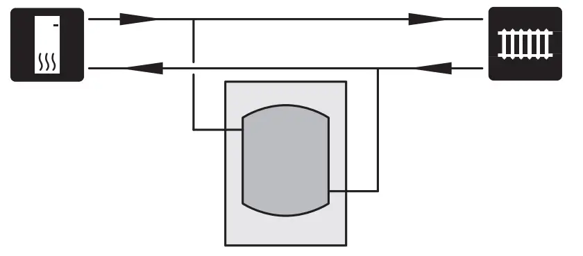
A UKV 40 is installed as a volume and flow increaser in those cases where the system volume in the climate system is below the minimum recommended volume for the heat pump and/or the flow is restricted without control.
Volume increase as well as reduction of heat spikes
A UKV 40 is installed as a volume increaser in those cases where the system volume in the climate system is below the minimum recommended volume for the heat pump.
PIPE INSTALLATION
Pipe installation must be carried out in accordance with current norms and directives.
The drain valve is installed on the heating system’s supply line (XL1).
The system where UKV 40 is installed must be supplied with a safety valve of max. 6 bar (0.6 MPa).
The overflow pipe must be the same size as the safety valve’s. Route the overflow pipe from the safety valve, sloping along its entire length, and ensure that it is frostproof and well supported. The mouth of the overflow pipe must be visible and not placed close to electrical components. Ensure that incoming water is clean.
If uncertain, contact a plumber alternatively see applicable standards.
FILLING
Fill the accumulator tank as follows:
- Vent the accumulator tank by loosening the connection (XL8) at the top of the accumulator tank.
- Fill the vessel through the drain valve.
- When only water comes out of the connection (XL8) (an air-water mixture emerges initially), the connection can be closed and the accumulator tank is filled.
Technical data
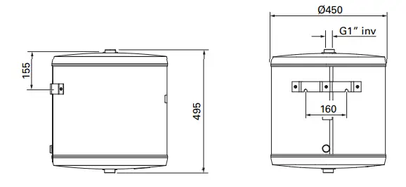
DIMENSIONS
UKV 40
PIPE CONNECTIONS
UKV 40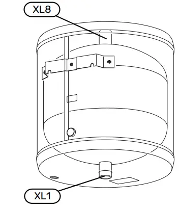
PIPE DIMENSIONS
| Connection | ||
| XL1 | Supply line, heating system | G1″ int. |
| XL8 | Docking from heat pump | G1″ int. |
TECHNICAL SPECIFICATIONS
| Model | UKV 40 | |
| Volume | litre | 39 |
| Net weight | kg | 16 |
| Max. operating pressure | MPa/bar | 0.6 / 6 |
| Max. operating temperature | °C | +4 – +95 |
| Part No. | 088 470 |
ENERGY LABELLING
| Supplier | NIBE | |
| Model | UKV-40 | |
| Efficiency class 1 | B | |
| Heat loss | W | 28 |
| Volume | l | 39 |
1 Scale for the product’s efficiency class A+ to F

NIBE Energy Systems
Hannabadsvägen 5
Box 14
SE-285 21 Markaryd
[email protected]
nibe.eu
©2023 NIBE ENERGY SYSTEMS 031532