steinel RS 16 LED Glass Ceiling Light Instruction Manual
About this document
Please read carefully and keep in a safe place.
- Under copyright. Reproduction either in whole or in part only with our consent.
- Subject to change in the interest of technical progress.
Symbols
![]() Hazard warning!
Hazard warning!![]() Reference to other information in the document.
Reference to other information in the document.
General safety notification
Disconnect the power supply before performing any work on the unit.
- During installation, the electric power cable to be connected must not be live. Therefore, switch off the power first and use a voltage tester to make sure the wiring is off-circuit.
- Installing the sensor-switched light involves work on the mains supply voltage. This work must therefore be carried out professionally in accordance with national wiring regulations and electrical operating conditions. (e.g.: DE: VDE 0100, AT: ÖVE / ÖNORM E8001-1, CH: SEV 1000)
- Only use genuine replacement parts.
- Repairs may only be made by specialist workshops.
RS 16 LED
Proper use
- Sensor-switched wall/ceiling light with active motion detector Limited suitability for outdoor use as a result of detection sensitivity
The integrated HF sensor emits high-frequency electromagnetic waves (5.8 GHz) and receives their echo. The change in echo caused by the slightest movement within the detection zone of the light is detected by the sensor. A microprocessor then issues the switch command “switch light ON”. Detection is possible through doors, panes of glass or thin walls.
Note:
The high-frequency power of the HF sensor is approximately 1 mW – 1000 times less than the transmission power of a mobile phone or microwave oven.
Package contents (Fig. 3.1)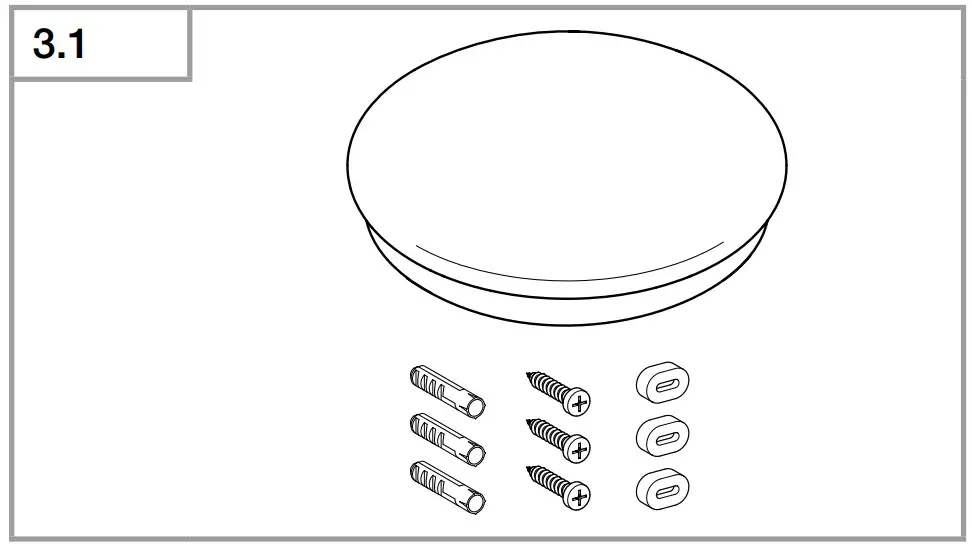
- Sensor-switched indoor lights
- three wall plugs
- three screws
- Three spacers
Product dimensions (Fig. 3.2)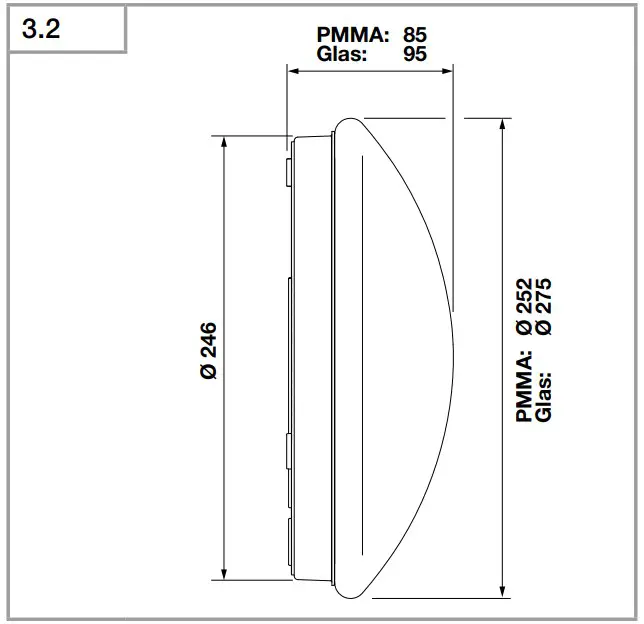
Product components (Fig. 3.3)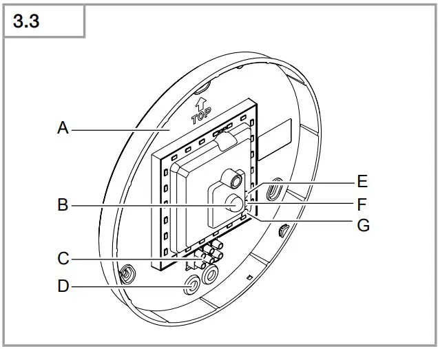
A Electronics enclosure
B HF sensor
C Connecting terminal
D Sealing plugs
E Time setting
F Reach setting
G Twilight setting
Detection zones for ceiling mounting
Ø 3-8 m (Fig. 3.4)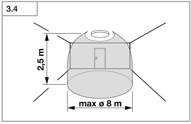
Detection zones for wall mounting
Ø 2.5 m (Fig. 3.5)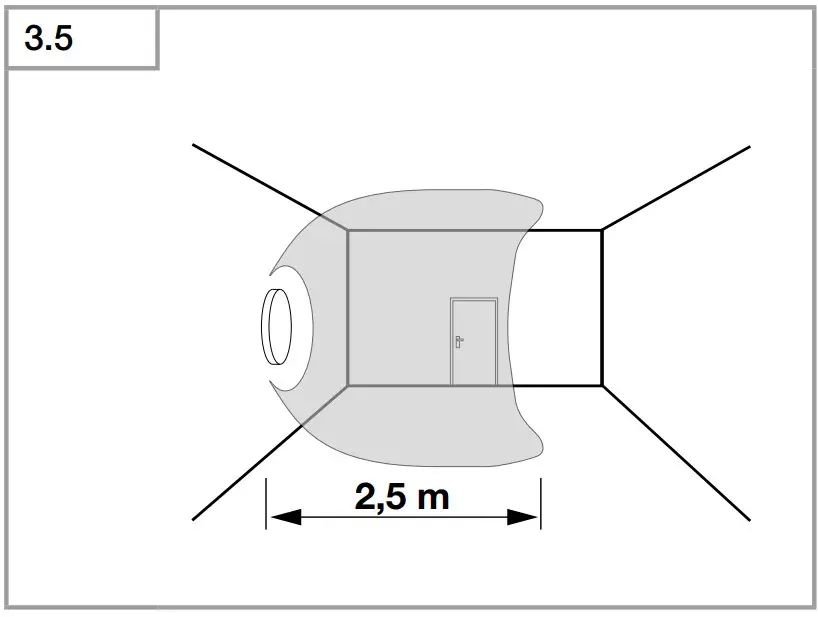
Luminous intensity distribution (Fig. 3.6)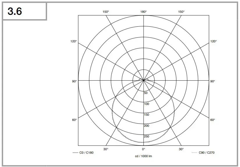
Electrical connection
Switch OFF power supply (Fig. 4.1)|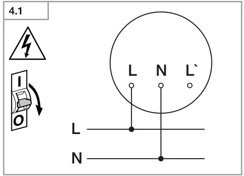
Wiring diagram (Fig. 4.1)
The mains power supply lead is a 3-core cable:
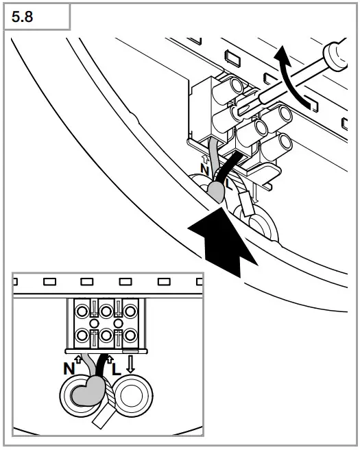
L = phase conductor (usually black, brown or grey)
N = neutral conductor (usually blue)
PE = protective-earth conductor (green/yellow)
L’ = switched phase conductor (usually black, brown or grey
If you are in any doubt, identify the conductors using a voltage tester; then disconnect from the power supply again. Connect phase , as well as the neutral conductor to the terminal.
Important:
Incorrectly wired connections will produce a short circuit later on in the product or your fuse box. In this case, you must identify the individual conductors once again and reconnect them. A mains power switch for turning the unit ON and OFF may of course be installed in the mains supply lead.
The light source of this luminaire cannot be replaced. If the light source needs to be replaced (e.g. at the end of its service life), the complete luminaire must be replaced.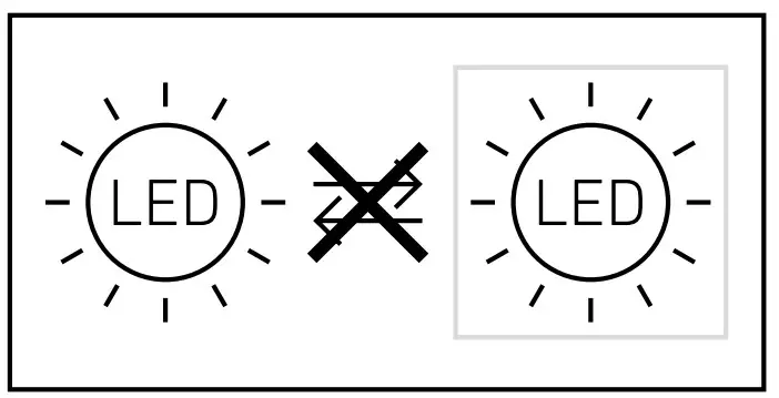
Connection to a dimmer will damage the sensor-switched light
Note:
Do not make direct contact with the LED.
Mounting
- Check all components for damage.
- Do not use the product if it is damaged.
- When installing the sensor-switched light, make sure the installation site is not subject to vibration.
- Select an appropriate mounting location, taking the reach and motion detection nto consideration.
Not suitable for ceiling mounting with surface-mounted power supply lead (Fig. 5.1)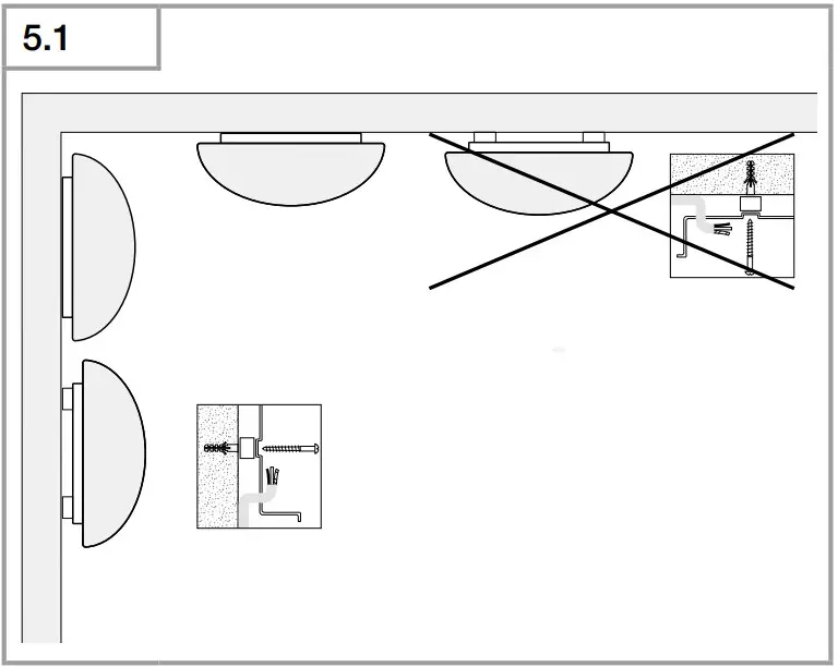
Mounting procedure
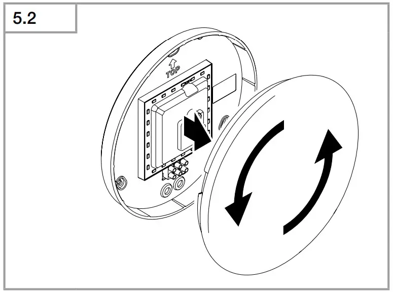
- Detach shade from enclosure (Fig. 5.2)

- Mark drill holes (Fig. 5.3)

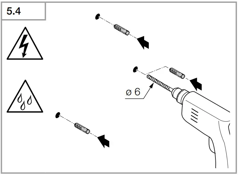
- Drill holes and insert wall plugs (Fig. 5.4)

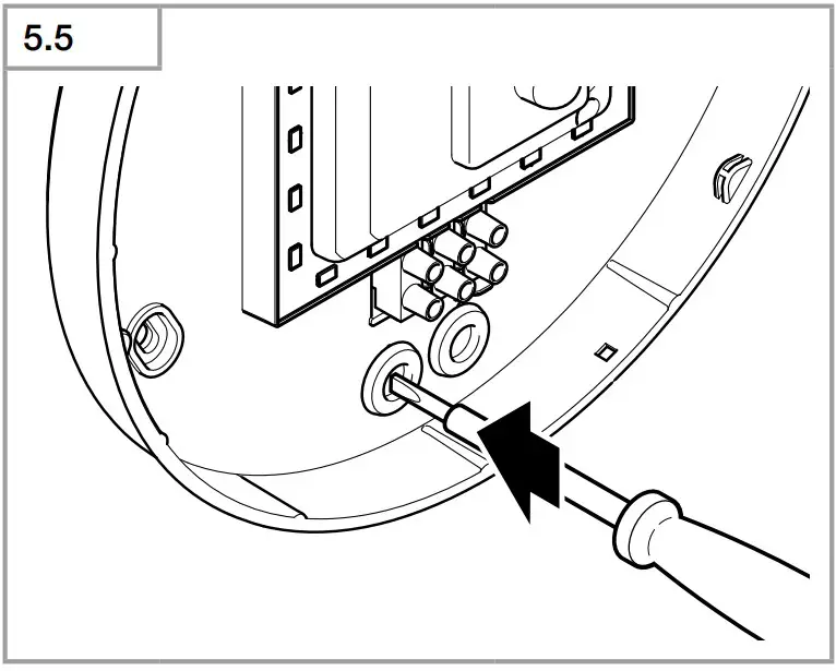
- Pierce sealing plug for power supply lead (Fig. 5.5)

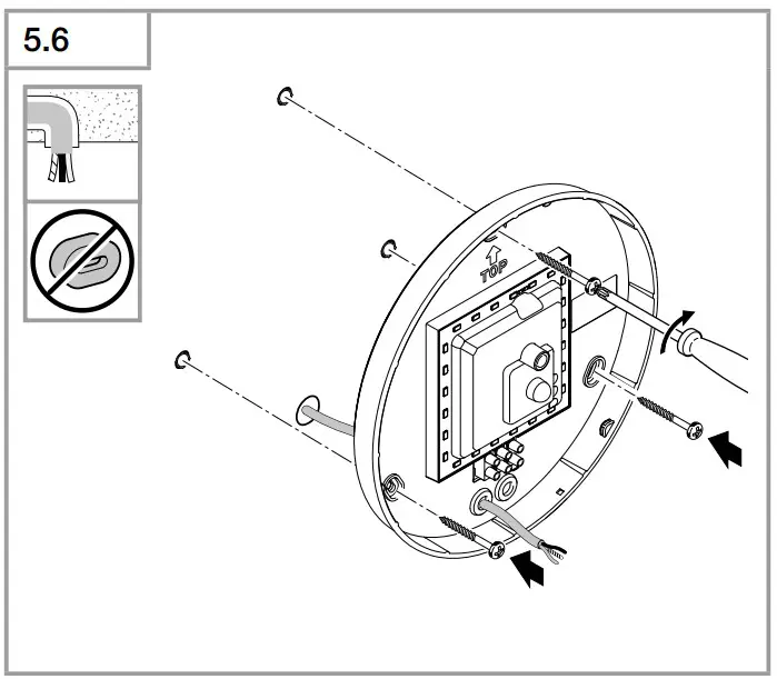
- Concealed wiring (Fig. 5.6)

- With spacers for surface mounting (Fig. 5.7)

- Connect conductors (Fig. 5.8)

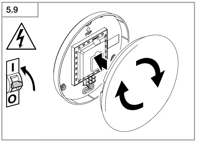
- Switch ON power supply (Fig. 5.9)

- Make settings ➜ “6. Function”
- Fit shade (Fig 5.9)


Function
- Factory settings:
- Twilight level: 2000 Lux
- Time setting: 5 s
- Reach setting: 8 m
The sensor-switched light can be put into service after mounting the enclosure and connecting to the mains power supply. When putting the light into operation manually at the light switch, it will switch OFF after 10 s for the calibration phase and is then activated for sensor mode. It is not necessary to operate the light switch a second time.
Control dial (Fig. 6.1)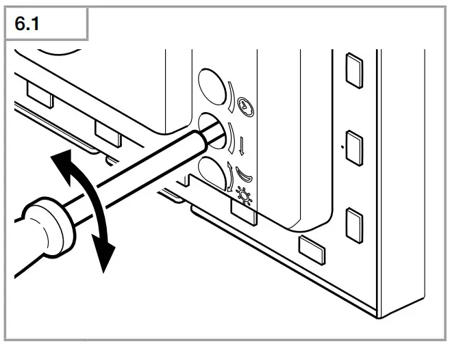
Time setting (stay-ON time) (Fig 6.2/E)
The light’s ON time can be set to any period from approx. 5 s to a maximum of 15 Min. Any movement detected before this time elapses will restart the timer.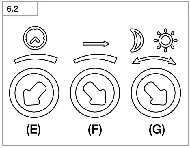
Note:
Whenever the light switches OFF, motion detection is interrupted for approx. 1 S. The light will only switch ON in response to movement once this period has elapsed. The shortest time setting is recommended when adjusting the detection zone and performing the functional test.
Reach setting (sensitivity) (Fig 6.2/F)
Reach is the term used to describe the diameter of the more or less circular detection zone produced on the ground after mounting the sensor-switched light at a height of 2.5 m.
- Control dial set to maximum = max. reach 8 m
- Control dial set to minimum = min. reach 3 m
Twilight setting (response threshold) (Fig 6.2/G)
The light’s chosen response threshold can be infinitely varied from approximately 2 to 2000 lux.
- Control dial set to
 = daylight operation (depending on ambient light level)
 - Control dial set to = twilight mode (approx. 2 lux)
The control dial must be turned to ![]() when adjusting the detection zone and performing the functional test in daylight.
when adjusting the detection zone and performing the functional test in daylight.
Manual override function
If an optional mains switch is installed in the mains supply lead, the following functions are available in addition to simply switching light ON and OFF:
Manual override (Fig. 6.3)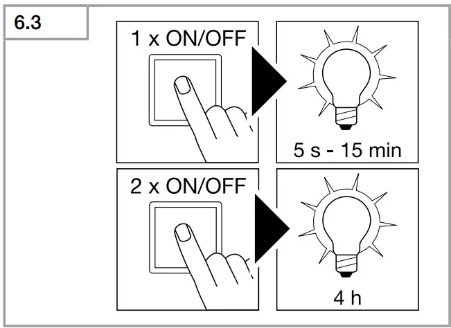
- Activate manual override:
Switch OFF and ON twice. The light is set to manual override for 4 hours. Then it returns automatically to sensor mode. - Deactivate manual override:
Switch OFF and ON once. Light goes out or switches to sensor operation.
Important:
Switching must take place within 0.2 to 1 second.
Disposal
Electrical and electronic equipment, accessories and packaging must be recycled in an environmentally compatible manner.

Do not dispose of electrical and electronic equipment as domestic waste.
EU countries only:
Under the current European Directive on Waste Electrical and Electronic Equipment and its implementation in national law, electrical and electronic equipment no longer suitable for use must be collected separately and recycled in an environmentally compatible manner.
Important note: the control gear cannot be replaced.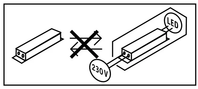
Manufacturer’s warranty
This Steinel product has been manufactured with utmost care, tested for proper operation and safety and then subjected to random sample inspection. Steinel guarantees that it is in perfect condition and proper working order. The warranty period is 36 months and starts on the date of sale to the consumer. We will remedy defects caused by material flaws or manufacturing faults. The warranty will be met by repair or replacement of defective parts at our own discretion. The warranty shall not cover damage to wear parts, damage or defects caused by improper treatment or maintenance. Further consequential damage to other objects shall be excluded.
Claims under the warranty will only be accepted if the unit is sent fully assembled and well-packed with a brief description of the fault, a receipt or invoice (date of purchase and dealer’s stamp) to the appropriate Service Centre.
Repair service:
If defects occur outside the warranty period or are not covered by warranty, ask your nearest service station for the possibility of repair.
Declaration of Conformity
STEINEL Vertrieb GmbH hereby declares that the RS 16 LED radio equipment type conforms to Directive 2014/53/ EU. The full wording of the EU Declaration of Conformity is available for downloading from the following Internet address: www.steinel.de
Technical specifications
| Dimensions (Ø x D) | PMMA Ø 280 × 110 mm Glass Ø 275 × 110 mm |
| Supply voltage | 220 – 240 V, 50 |
| Power consumption (Pon) | PMMA 9.5 W Glass 9.3 W |
| Luminous flux (360°) | PMMA 958 lm Glass 918 Im |
| Efficiency | PMMA 100 lm/W Glass 98 lm/W |
| Sensor on standby (Psb) | 0.39 W |
| Mains current | 46.50 mA AC |
| Power factor | 0.94 |
| Additional switching capacities | |
| Incandescent / halogen lamp load | max. 800W |
| Fluorescent-lamp electronic ballasts | max. 400 W |
| Fluorescent lamps, uncorrected | max. 400 VA |
| Fluorescent lamps, series-corrected | max. 400 VA max. 400 |
| Fluorescent lamps, parallel-corrected | max. 400 VA |
| Low-voltage halogen lamps | max. 800 VA |
| LED < 2 W | 16 W |
| 2 W < LED < 8 W | 64 W |
| LED > 8 W | 64 W |
| Capacitive load | 88 μF |
| Colour temperatur | PMMA 4,000 K (neutral white) Glass 3,000 K (warm white) |
| Colour rendering index | Ra = 82 |
| Average rated life expectancy | L70B50 at 25°C: >60,000 hours |
| Colour consistency SDCM | Starting value: 3 |
| Luminous intensity distribut | 5.8 GHz (responds to the slightest movement regardless of temperature |
| HF technology | 360° with 160° angle of aperture |
| Angle of coverage | approx. 1 mW |
| Transmitter power | Ø 3 – 8 m |
| Time setting | 5 s – 15 mi |
| Twilight setting | 2 – 2,000 lux |
| IP rating | IP44 |
| Protection class | II |
| Temperature range | -10 to +40°C |
| Energy efficiency class | This product contains an energy efficiency class “E” light source. |
Troubleshooting
| Malfunction | Cause | Remedy |
| Sensor-switched light without power |
|
|
| Sensor-switched light will not switch ON |
|
|
| Sensor-switched light will not switch OFF |
|
|
| Sensor-switched light switches ON without any identifiable movement |
|
|
| Sensor-switched light does not switch ON despite movement |
|
|
STEINEL Vertrieb GmbH
Dieselstraße 80-84
33442 Herzebrock-Clarholz
Tel: +49/5245/448-188
www.steinel.de
Contact
www.steinel.de/contact

110081306 11/2021 Subject to technical modification without notice.


