![]()
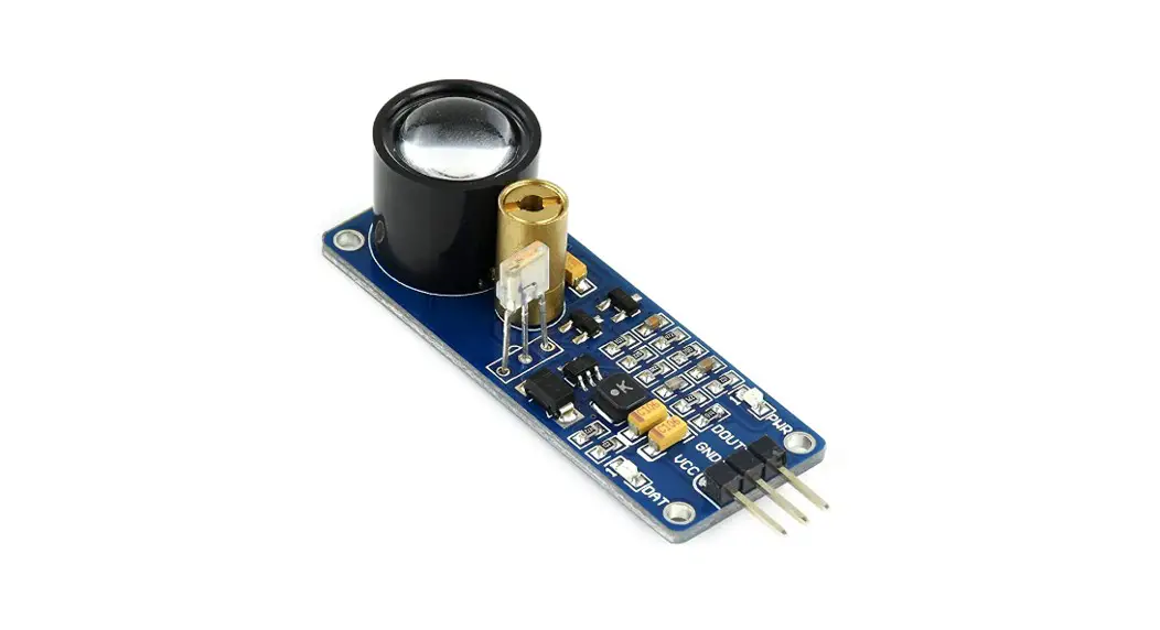
![]() PT1301 Laser Sensor
PT1301 Laser Sensor
User Manual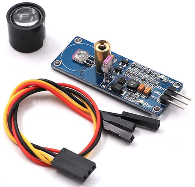
Features
| Boost converter chip | PT1301 |
| Operating voltage | 2.5V-5.0V |
| Dimensions | 53.0mm*18.0mm |
| Fixing hole size | 2.0mm |
| Effective distance | 0.8m(typ), 1.5m(max) |
Operating principle:
A laser sensor contains a transmitter and a receiver.
In the transmitter, there is an oscillating tube can generate a shockwave in a frequency of 180KHz. After amplified by a transistor, the shockwave is applied to the laser tube for exciting.
In the receiver, there is a receiving tube, matching to the oscillating tube, can receive the reflected light. Since the laser sensor adopts modulation processing technology, the receiving tube can only receive the reflected light in a same frequency, efficiently preventing from the visible light.
Applications
This module can be applied to obstacle detection, counter device in the pipeline intellectual robot, obstacle avoidance car, etc.
Interface
| Pin No. | Symbol | Descriptions |
| 1 | DOUT | Digital output |
| 2 | GND | Power ground |
| 3 | VCC | Positive power supply (2.5V-5.0V) |
How to use
We will illustrate the usage of the module with an example of obstacle detection by connecting a development board.
- Download the relative codes to the development board.
- Connect the development board to a PC via a serial wire and the module to the development board. Then, power up the development board and start the serial debugging software.
Here is the configuration of the connection between the module and the development board.Port STM32 MUC pin DOUT GPIOA.4 GND GND VCC 3.3V Port Arduino pin DOUT D2 GND GND VCC 5V - The detected result can be checked by a signal indicator on the module.
The signal indicator will turn on, when a barrier is placed above the sensor. - And the signal indicator will turn off, when the barrier is away from the sensor.
Notices: Laser directly to eyes is forbidden, which will hurt the eyes.
![]()


