![]()
FLD-mini flashlamp driver
User manual
Warning! This equipment produces high voltages and can be dangerous. Please read user manual before starting operations.
Description
FLD-mini is a miniature all-in-one flashlamp driver specially designed to drive solid-state lasers like flashlamp pumped Nd:YAG, Er:YAG etc.
Driver includes embedded capacitor charging power supply, small capacitor bank, IGBT, its driver, protective circuits, simmer and trigger circuits, discharge resistors and controls, in other words, everything needed to form on flashlamp pulses of quasi-rectangular shape using the energy stored in embedded capacitor bank.
Driver’s major features are:
- 24V DC input (48V DC on request)
- Maximal output power – 300W (base version, up to 400W with 24V DC input, up to 700W with 48V DC input)
- Maximal output voltage – 450V (base version, up to 700V on request)
- Built-in 2mF capacitor bank
- Flashlamp trigger and simmer circuits
Base interface is RS-232 (RS-485 is available as an option). Simple PC software is supplied together with the controller.
Driver contains a fan for active cooling.
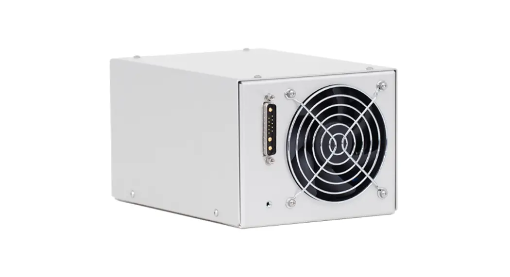
Appearance
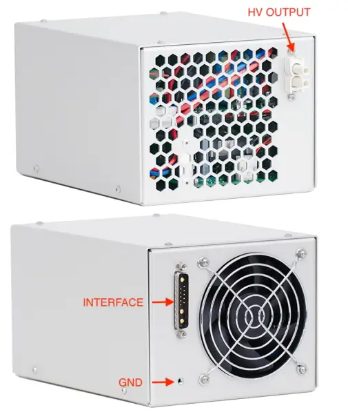
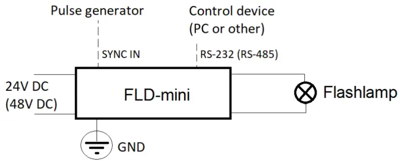
Connections, signals, signal descriptions
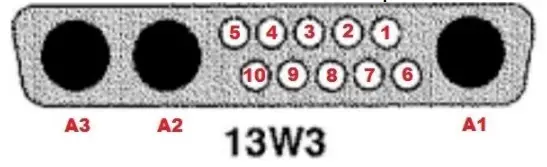
INTERFACE: 13 pin mixed D-SUB connector of 13W3 type
The INTERFACE serves for 24V DC power and all the control signals connection.
RS-232 modification:
| PIN (color) | DESIGNATION | DESCRIPTION |
| 1, 2 (transparent) | RS-232 GND | The control device connection (RS-232 interface). |
| 3 (orange) | RS-232 RX | |
| 4 (blue) | RS-232 TX | |
| 5 (green) | IDC | Door-interlock connection. Should be pulled to the ground to allow the operations. |
| 6 (violet) | Fault | Module internal failure indication. Module rises Fault in the next cases: – Overheating – Unable to charge capacitors – Unable to trigger flashlamp – Other failures |
| 7 (white/blue) | Synchro IN | Incoming synchronization pulses should be applied to this pin if module is running in external synchronization mode. Input impedance is approx. 1.6 kOhm |
| 8 (white) | Synchro OUT | Synchro output signal coincided with pulse applied to the flashlamp (other on request) |
| 9, 10 (black) | Interface Return | Common return of all interface circuits |
| A1 (yellow/green) | GND | This pin can be used for protective grounding instead of GND thread. |
| A2 (red) | DC Input | 24V DC power supply connection. Maximal current consumption is 17A. |
| A3 (black) | DC Input Return |
RS-485 modification difference (other signals are identical to RS-232 modification):
| PIN (color) | DESIGNATION | DESCRIPTION |
| 1, 2 (transparent) | N/C | – |
| 3 (orange) | RS-485 A | The control device connection (RS-485 interface). |
| 4 (blue) | RS-485 B |
HV OUTPUT: Proprietary connector by OEM Tech
Flashlamp is to be connected here.
Red wire – HV OUTPUT positive (to flashlamp anode)
Black wire – HV OUTPUT negative (to flashlamp cathode)
GND: M4 thread
Module should be grounded using this thread before switching on.
Grounding policy
HV OUTPUT negative and 24V DC return are connected to each other, though isolated from the chassis ground and controlling circuits.
RS-232/485 and other Interface signals are isolated from each other and from power circuits.
Other grounding policies are available on request.
Safety
Warning! This equipment produces high voltages that can be very dangerous.
Be careful around the equipment.
Assemble the entire setup before powering up the device.
- Power supply enclosure is to be protectively grounded via provided grounding stud.
- Use low voltage power supply with DC output galvanically insulated from AC input (insulation strength 4000VAC, 2500VAC or 1500VAC is selected in dependence on your application)
- Do not connect / disconnect output cables while driver is turned on
- Do not operate with disconnected load
- Avoid casual contacts of personnel with output cables and with the load
- Do not turn the power supply on if it was already damaged with water, chemicals, mechanical or electrical shock
- Do not self-repair the power supply, there are no user-serviceable parts inside
First-run procedure
- Ensure 24V DC power supply is off
- Connect flashlamp, 24V DC power supply and the controlling device to FLD-mini. Ground FLD-mini using provided thread
- Organize your IDC connection or just short-circuit IDC with a choke
- Switch on FLD-mini by turning on 24V DC power supply
- Connect to FLD-mini via RS-232 interface (baud rate 38400; 8 data bit; 1 stop bit; no parity) or via RS-485 interface
- Install and run provided software to set the driver parameters
- Now your flashlamp driver is ready to work
For more details see also Software description section on page 10 and Operations section on page 14
Specifications
ELECTRICAL
| DC INPUT: | |
| Input voltage | +24V DC (48V DC in optional high-power version which is available on request) |
| Current consumption | 17A max |
| PULSE PARAMETERS: | |
| Max. voltage | 450V (base version, up to 700V on request) |
| Max. discharge current | 500A |
| Max. average power | 300W (base version, up to 400W with 24V DC input, up to 700W in optional high-power version with 48V DC input which is available on request) |
| Pulse width | 50us-1000us |
| Repetition rate | 1-30Hz |
| WIRE INSULATION NOTE: | |
| For flashlamp connections | Due to series triggering with 10kV pulses additional insulation (e.g. with silicone tubing) or spacing (e.g. with spiral bundle hose) of L– wire is required |
| SIMMER PARAMETERS: | |
| Simmer current | 500 mA (100-800 mA on request) |
| Max output voltage | 300 V |
| Max output power | 100 W |
| Open circuit voltage | 1500 V |
| FLASHLAMP TRIGGERING PARAMETERS: | |
| Triggering method | Series triggering with built-in transformer (external triggering on request) |
| Pulse energy / trigger voltage | ~160mJ / 10kV negative to L– (other on request) |
| Trigger pulse width | ~1 us |
| Restrike rate | A few Hertz (automatically adjusted) |
| COOLING | Forced air cooling with an integrated fan |
| PROTECTIONS | From overheating of internal components |
| ENVIRONMENT: | |
| Operation temperature | 0 … +40 °C |
| Storage temperature | -20 … +60 °C |
| Humidity | 90%, non-condensing |
MECHANICAL
| Size (LxWxH) | See dimensional drawing below |
| Weight | Approx. 2.0 kg (w/o cables) |
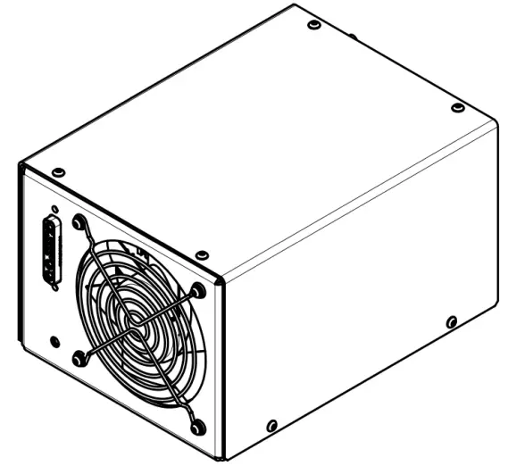
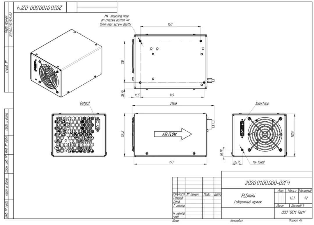
DIMENSIONAL DRAWING (STANDARD VERSION)
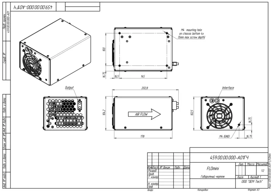
DIMENSIONAL DRAWING (COMPACT VERSION)
How to order?
By default FLD-mini is supplied with the next parameters:
- 24V DC input voltage
- 450V maximal output voltage
- 2mF embedded capacitor bank (maximal rated voltage 450V)
- 300W maximal output power (achieved close to 450V)
- Serial triggering
- RS-232 interface
If the default parameters are not suitable for your application, please fill in and send to us the form below:
| Parameter | Options available (please select one) |
| Input voltage | □ 24V DC □ 48V DC |
| Maximal output voltage | □ 350V (embedded capacitor bank 2.7mF) □ 450V (embedded capacitor bank 2.0mF) □ 500V (embedded capacitor bank 1.5mF) □ 700V (embedded capacitor bank 0.7mF) |
| Maximal output power | With 24V DC input: □ 200W □ 300W □ 400W With 48V DC input: □ 500W □ 700W |
| Triggering | □ Serial □ External □ Both serial and external |
| Interface | □ RS-232 □ RS-485 |
Alternatively please provide a free-form description of your needs.
Software description
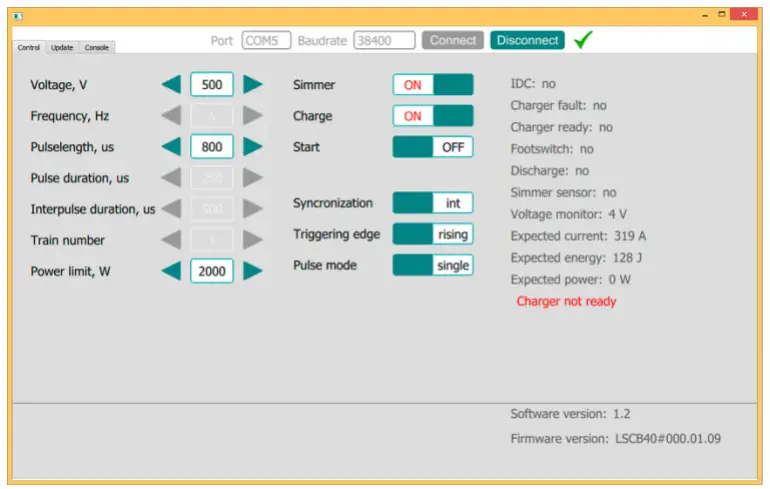
Voltage – sets the desired output voltage (V)
Frequency – sets the desired repetition rate of flashes (Hz)
Pulse length – sets the desired pulse width (us)
Charge – turns capacitor charging module on and off
Simmer – turns simmer supply on and off
Start – enables and disables flashes at HV output
Synchronization – select synchronization mode – Internal synchronization / External synchronization In Internal synchronization mode flashes are defined by internal MCU In External synchronization mode flashes are defined by external signal applied to SYNC IN signal of INTERFACE connector
Triggering edge – in External synchronization mode defines the trigger edge of synchronization signal – either rising edge or falling edge
IDC – status of Door Interlock (IDC signal of INTERFACE connector) – flashes are prohibited if IDC loop is open
Charger fault – internal fault status of the capacitor charging power supply
Charger ready – Ready signal of the capacitor charging power supply
Discharge – status of discharge resistors
Voltage monitor – the actual voltage on the built-in capacitor bank
Expected current – the calculated current through the flashlamp (calculations are based on Voltage and Flashlamp impedance K0 values)
Expected energy – the calculated flash energy (calculations are based on Voltage, Flashlamp impedance K0 and Pulse length values)
Expected power – the calculated power through flashlamp (calculations are based on Voltage, Flashlamp impedance K0, Pulse length and Frequency values)
Lamp impedance K0 – value from flashlamp d/s
RS-232/485 protocol description (firmware revisions #3.2.XX)
RS-232/485 connection parameters: 38400 bps, 8 data bit, 1 stop bit, no parity
Command format is: {command} {data (optionally)} {end-of-line}
- Command is 1 to 4 character long (see list below)
- Data is ASCII-string, command and data must be separated with space (space symbol)
- End-of-line symbols are \n or \r\n
List of available commands:
| # | Command | Description | Possible values | |||
| Min | Max | Inc | Def | |||
| 1 | sn | Sets device’s serial number (example «sn 123») | 0 | 65535 | 1 | 0 |
| 2 | SN | Returns device’s serial number (ID) | 0 | 65535 | 1 | |
| 37 | * | Returns firmware version | ASCII string up to 15 characters long | |||
| 40 | !J | Returns pulse counter | 0 | ~4.29 109 | 1 | 0 |
| 41 | #J | Resets pulse counter | – | – | – | – |
| 3 | v | Sets the desired output voltage (in volts, example «v 300») | 100 | 450 | 1 | 100 |
| 4 | V | Returns voltage set point (not voltage monitor) | 100 | 450 | 1 | |
| 5 | p | Sets the desired pulse width (in us, example «p 250») | 50 | 1000 | 1 | 50 |
| 6 | P | Returns pulse width set point | 50 | 1000 | 1 | |
| 7 | f | Sets the desired pulse repetition rate (in hz, example «f 0.5», 0 means single shot) | 0, 0.05 | 30 | 0.01 | 1 |
| 8 | F | Returns repetition rate set point | 0, 0.05 | 30 | 0.01 | |
| 9 | x | Sets the synchronization mode («x 0» – internal, «x 1» – external) | 0 | 1 | – | 0 |
| 10 | X | Returns the synchronization mode | 0 | 1 | – | |
| 11 | t | Sets trigger edge in external synchronization mode («t 0» – rising, «t 1» – falling) | 0 | 1 | – | 0 |
| 12 | T | Returns trigger edge | 0 | 1 | – | |
| 35 | xo | Defines how synchro output is generated while module is run in external synchronization mode («xo 0» – synchro output is generated by MCU, correspondingly, if necessary, it can differ from incoming pulse, though by the cost of the additional delay; «xo 1» – pulse of external synchronization is repeated at the synchro output, correspondingly the delay is minimal) | 0 | 1 | – | 0 |
| 36 | XO | Returns the mode | 0 | 1 | – | |
| 13 | s | Turns the simmer supply on and off («s 1» – on, «s 0» – off) | 0 | 1 | – | 0 |
| 14 | S | Returns the simmer supply set point (not simmer monitor) | 0 | 1 | – | |
| 15 | c | Turns the capacitor charging module on and off («c 1» – on, «c 0» – off) | 0 | 1 | – | 0 |
| 16 | C | Returns capacitor charging module set point | 0 | 1 | – | |
| 17 | r | Enables / disables the output («r 1» – enables) | 0 | 1 | – | 0 |
| 18 | R | Returns the corresponding set point | 0 | 1 | – | |
| 19 | h | Sets maximal power limit (in watts, example «h 200», 0 disables the protection) | 0 | 400 | 1 | 300 |
| 20 | H | Returns maximal power limit | 0 | 400 | 1 | |
| 21 | !i | Sets maximal current limit (in amps, example «!i 1000», 0 disables the protection) | 0 | 650 | 1 | 650 |
| 22 | !I | Returns maximal current limit | 0 | 650 | 1 | |
| 23 | !k0 | Sets flashlamp impedance used for calculations (in VA-1/2, example «!k0 28», 0 disables both over-power and over-current protections) | 0 | 50 | 0.1 | 0 |
| 24 | !K0 | Returns flashlamp impedance | 0 | 50 | 0.1 | |
| 25 | mV | Voltage monitor (volts) | 0 | 500 | 1 | – |
| 26 | mF | Returns fault state (0 – no fault, 1 – fault). Once fault has been occurred, the module: – Stops pulses (“r 0”) – Stops the charger (“c 0”) – Stops the simmer (“s 0”) – Sets fault code (mJ) Once fault cause disappears, Fault state is automatically removed. Information about the last fault is stored in the error code (mJ). | 0 | 1 | – | 0 |
| 27 | mR | Returns ready state (status of the capacitor charging module, 0 – not ready, 1 – ready) | 0 | 1 | – | – |
| 28 | mI | Returns IDC state (0 – closed, 1 – open) | 0 | 1 | – | – |
| 29 | mS | Returns simmer sensor state (0 – off, 1 – on) | 0 | 1 | – | – |
| 38 | sw | Sets simmer sensor timeout (is seconds, example «sw 1», 0 disables the protection); if simmer arc is lost for the time lesser than the timeout value, this situation is not considered as a fault | 0 | 5 | 0.1 | 3 |
| 39 | SW | Returns simmer sensor timeout | 0 | 5 | 0.1 | |
| 30 | mD | Returns state of built-in discharging resistors (0 – no discharge, 1 – discharging) | 0 | 1 | – | – |
| 31 | mJ | Returns error code 0 – No error 1 – IDC is open 2 – Charger’s internal fault 3 – Simmer triggering failed on start (“s 1”) 4 – Simmer arc has been ost in run mode 5 – PC connection error (i.e. watch-dog error, see wdg command) 6 – Power too high (exceeds the limit set with h command) 7 – Current too high (exceeds the limit set with !i command) Error code will be removed (set to 0) on the next successful start (“r 1”) | 0 | 7 | 1 | 0 |
| 32 | mP | Returns expected power (watts) | 0 | 65535 | 1 | – |
| 33 | mC | Returns expected current (amps) | 0 | 65535 | 1 | – |
| 34 | mE | Returns expected energy (jouls) | 0 | 65535 | 1 | – |
| Service commands | ||||||
| 42 | ^c | Calibrates output voltage (in volts, one point calibration) | VMAX-10 to VMAX+10 | 1 | – | |
| 43 | ^C | Returns the corresponding value | 1 | – | ||
| 44 | ^k | Calibrates voltage monitor (in volts, one point calibration) | VMAX-10 to VMAX+10 | 1 | – | |
| 45 | ^K | Returns the corresponding value | 1 | – | ||
| 46 | _R | Resets calibrations (both voltage and monitor) | – | – | – | – |
| 49 | wdg | Sets watch-dog timeout (in seconds, example “wdg 5”, 0 means timeout is disabled); no command received via RS-232 interface within this time is considered as a communication error | 0 | 10 | 0.1 | 5 |
| 50 | WDG | Returns watch-dog timeout | 0 | 10 | 0.1 | |
| 51 | vm | Sets capacitor charger’s calibration (VMAX) | 0 | 500 | 1 | 450 |
| 52 | VM | Returns VMAX | 0 | 500 | 1 | |
| 53 | widc | Sets IDC waiting time (ms) | 1 | 6000 | 1 | 200 |
| 54 | WIDC | Returns IDC waiting time (ms) | 1 | 6000 | 1 | |
| 55 | ss | Slow start time (in seconds, 0 – disabled) | 0 | 60 | 1 | 0 |
| 56 | SS | Returns slow start command | 0 | 60 | 1 | |
| 57 | mvp | HV power supply calibration constant | 0 | 10 | 0.1 | 7 |
| 58 | MVP | Returns HV power supplycalibration constant | 0 | 10 | 0.1 | |
| 47 | #R | Resets EEPROM (sets all parameters to the default values) | – | – | – | – |
| 48 | boot | Switches MCU to the bootloader mode | – | – | – | – |
| 55 | #SM | Saves all parameters to EEPROM | – | – | – | – |
| – | @, %, ? | Service commands left for compatibility purposes (not recommended to use) | – | – | – | – |
| – | ^V, !R, #f | Service commands left for compatibility purposes (not recommended to use) | – | – | – | – |
Operations (start-up and shut-down procedures)
- Connect flashlamp, 24V DC power supply and the controlling device to FLD-mini. Ground FLD-mini using provided thread. Organize your IDC connection or just short-circuit IDC with a choke.
- Switch on FLD-mini by turning on 24V DC power supply.
- Connect to FLD-mini via RS-232 interface (baud rate 38400; 8 data bit; 1 stop bit; no parity).
- Check if the connection has been established successfully by sending some test commands (e.g. ‘mF’ or ‘mV’). The response should be adequate to the command.
- Setup the initial parameters following the sequence below:
• set flashlamp impedance using ‘!k0’ command (example ‘!k0 20.5’; ‘!k0 0’ disables over-current and over-power protections)
• check if the flashlamp impedance has been set correctly using ‘!K0’ command
• set maximal current limit using ‘!i’ command
• check if current limit has been set correctly using ‘!I’ command
• set maximal power limit using ‘h’ command
• check if power limit has been set correctly using ‘H’ command
• set synchronization mode using ‘x’ command
• ‘X’ to check
• if necessary set synchronization edge using ‘t’ command
• ‘T’ to check
• set desired output voltage using ‘v’ command
• ‘V’ to check
• set desired pulse width using ‘p’ command
• ‘P’ to check
• set desired repetition rate using ‘f’ command
• ‘F’ to check - After the initial setup is done, start the internal sub-modules one-by-one:
• send ‘s 1’ command for the flashlamp triggering
• after approx. 2s waiting time check the simmer arc status by sending ‘mS’ command
• on positive response, send ‘c 1’ command for enabling capacitor charging power supply
• after approx. 2s waiting time check if the capacitor bank is charged successfully either by sending ‘mR’ command or by sending ‘mV’ command (there might be some difference between set and measured value, usually 1-2% of VMAX) or both
• on positive response, send ‘r 1’ command to apply pulses to the flashlamp - Operating voltage, pulse width and the repetition rate can be changed in run mode. Synchronization parameters cannot be changed in run mode.
- In run mode we recommend to monitor the internal state of FLD-mini using the next commands:
• R – if FLD-mini is in run mode
• mJ – error code
Recommended frequency of sending commands is 5Hz or less. - Shut down sequence:
• ‘r 0’ to stop pulses
• ‘s 0’ to off the simmer
• ‘c 0’ to disable the capacitor charging
Note: capacitor banks need some time (15-20s) to discharge down to safe voltage level.
• disable RS-232 connection
• remove 24V DC power
![]()


