 JVA WA20M Solar Panels
Introduction
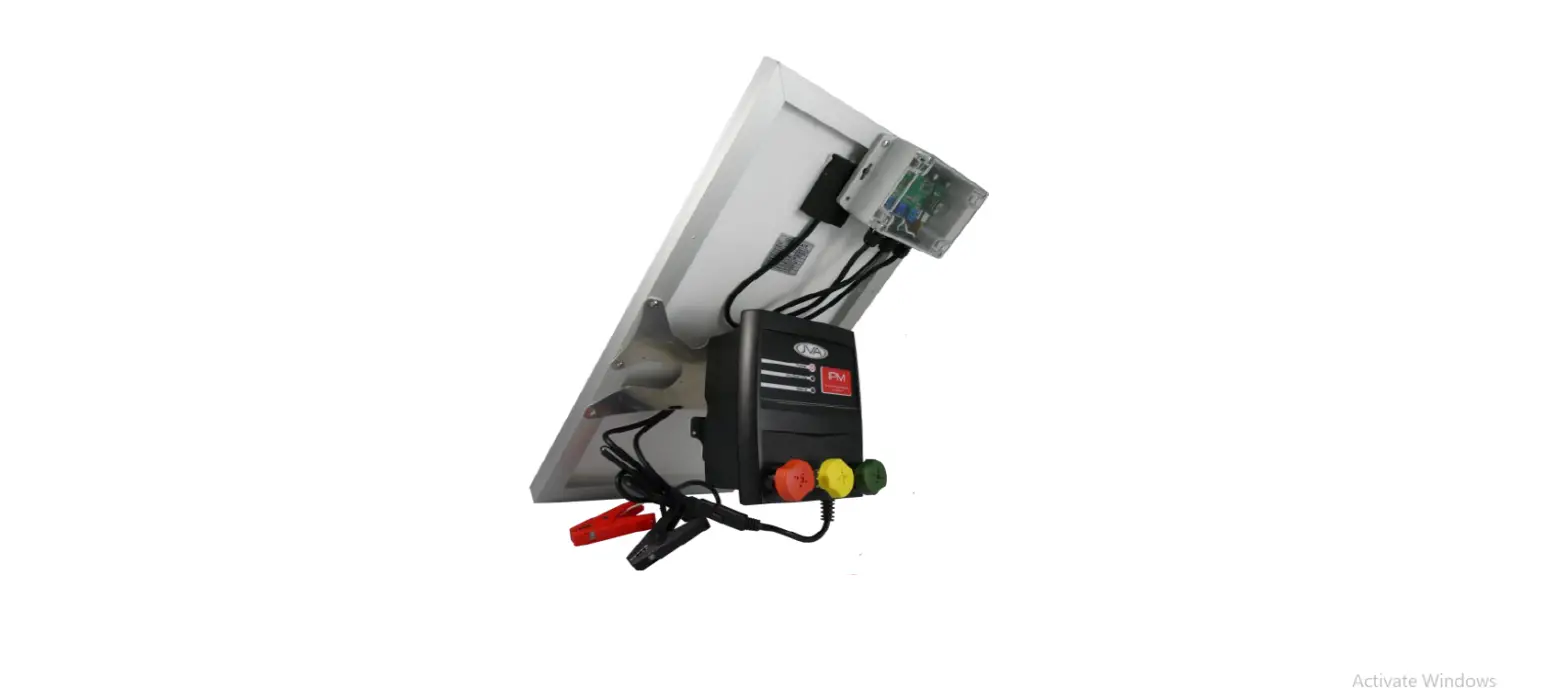
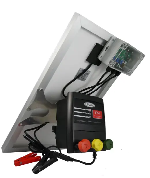
The PTE2701 JVA Wi-Fi Fence Monitor provides an integrated Wireless Cellular USB Dongle (Wingle) power supply with a solar battery charger and management system.
This product provides a Wi-Fi network wherever a 3G/4G signal is avail-able*. The Wi-Fi can then be used to connect an IP device or Internet of Things (IoT) device to the Cloud (Internet).
The JVA Solar Wi-Fi Fence Monitor is paired with the Wingle at the fac-tory, all you need to do is:
- Register the SIM card
- Add the Fence Monitor to the IP Energiser Controller app on your iOS or Android device
This quick-start guide explains how to connect your PTE2701 to a fence and turn it on.- An external cellular antenna (included) may be connected to increase reception. An upgraded YAGI style antenna is available from [email protected]
Specifications
| Component | Information |
| Solar Panel | Nominal 12v Solar Panel (maximum open circuit voltage – 22v DC) Maxmium Power 20W |
| Battery | Nominal 12.8v DC Minimum Battery size 18Ah A larger battery may be required if any addiontal 12v device is connected to the battery |
| Component | Information |
| Outputs(1) | 12v DC SAE Connector Used for powering the IP Monitor |
| Outputs (2) | 12v DC Battery Connector Alligator clips for battery connection |
| SIM | Full Size |
| Wi-Fi | 2.4GHz b/g/n Up to 10 connections at a time |
| Network (Huawei E8372) | 3G 850/2100MHz 4GX 700MHz + 4G B1/3/7/21 |
| Antenna Connector | Female SMA Ensure antenna is mounted away from sources of interference such as AC or high voltage cables. |
Troubleshooting
| Fault | Likely Cause | Remedy |
| No lights are on | Power is not connected
Power wires are re- versed | Check power connec- tions Check battery polarity |
| Batt level flashing | Battery disconnected
Bad battery | Check battery connec- tions Check battery voltage |
| USB_5V LED off | USB device drawing too much current | Unplug USB device, check for damage/ seek manufacturer advice |
| Fault | Likely Cause | Remedy |
| Battery not charging | Solar wiring backwards | Check that the Solar + goes to the left-hand screw terminal |
| Broken cables | Check that the battery cables are not dam- aged | |
| Solar panel broken | Check solar panel for physical damage (bro- ken glass, bent frame etc.) | |
| Cannot connect to Wi-Fi | Low signal from 3G/4G | Check management page of Wingle |
| Out of Wi-Fi range (~10m) | Move closer to Wingle | |
| SIM card not inserted correctly | Re-insert SIM card |
If the unit is still not working correctly, contact your nearest JVA distributor
for technical support.
Troubleshooting the IP Monitor
| Fault | Liklely Cause | Remedy |
| Status LED off | Power failure | Check connections and battery level |
| Status LED green | Normal operation, connected to internet and ready to operate | No action necessary |
| 1 Red flash | IP Monitor is not con- nected to Wi-Fi, this is factory default mode | Configure the IP Monitor to connect to the Wingle’s Wi-Fi network |
| Fault | Liklely Cause | Remedy |
| 2 Red flashes | IP Monitor has re- ceived Wi-Fi configu- ration and is attempt- ing to connect to Wi-Fi network | If persistent (more than 2 minutes) Factory default and try to configure again |
| 3 Red flashes | IP Monitor is connect- ed to Wi-Fi and is con- nected to the internet | This should not dis- play for more than 20 seconds, after which it will turn green. No action necessary |
| 4 Red flashes | Failed to connect to Wi-Fi, the unit will try again | If this persists, fac- tory default and try to configure again. If more than 10m away from Wingle, move closer. |
| 5 Red flashes | IP Monitor has incor- rect password | Default the IP monitor and re-configure |
If the unit is still not working correctly, contact your nearest JVA distributor for technical support.
Before you start
Activate the SIM card
Activate your SIM card and test it in a mobile phone. The Wi-Fi network allows a data-only connection, the number of devices connected to the module will determine how much data will be used.
As a guide, a single IP Energiser or IP Monitor will use less than 1MB per day, so for connecting a single IP Energiser, an upper limit of 500MB per year is an option with a lot of headroom.
Overview
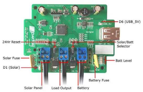
| D1 (Solar) | Solid on when solar panel in sunlight Blinking when solar panel in low power conditions Off when no solar power detected |
| D6 (USB_5V) | Solid on when USB Power is turned on |
| Batt Level | Bottom LED flashes if no battery is disconnected or bad Shows battery level from bottom to top: 25% to 100% |
Configure IP energizer Controller App
Download the IP Energiser Controller application (IPEC) from the app store or google play.
Add a site to your IPEC app:
- Press the menu hamburger at the top left
- Press “Add Site”
- Name the Site anything appropriate e.g. “North East 6km”
- Fill in the Unit Serial Number with the serial number of the IP Monitor. This can be found on the bottom at the back of the IP Monitor.
- Fill in the Unit Password with the same Serial Number used just before. The default password set by factory is the serial number of the IP Monitor.
- Select the “Device Type” as “IP Monitor”
- Set alarm thresholds for voltage and current accordingly. The IPEC app will notify you if the IP Monitor hits or exceeds these thresholds.
- Press “OK”
Connect IP Monitor
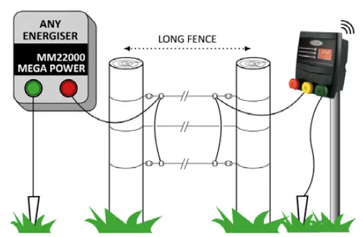
Option 1 – Monitor the end of a fence
- Turn off Energiser before starting
- Green Terminal to Fence Ground (Earth)
- Yellow Terminal to Fence Live
Red Terminal (nothing connected) Advantages
- End of Fence Voltage Monitoring
- Cut detection
- Fence Load detection
Limitations - No Current monitoring
- No fence armed state control1
1. Relay function not available on IPM variant (PTE2606) – requires IPM-R
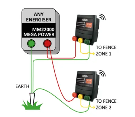
Option 2 – Monitor from the start of the fence(s)
Turn off Energiser before starting
- Green Terminal to Fence Ground (Earth)
- Yellow Terminal to Fence Live
- Red Terminal to Energiser
Output (high voltage) Advantages
- Current Monitoring
- Voltage Monitoring
- Ability to control the fence armed state1
Limitations: - No cut detection
- Relay function not available on IPM variant (PTE2606) – requires IPM-R
Battery Connection and First Power On
Connect the battery to the PTE2701 by the included battery connection cables. Ensure that the positive is connected to the red connector and the negative to the black connector.
Once connected, the Batt Level indicator lights will show the approximate voltage level of the battery.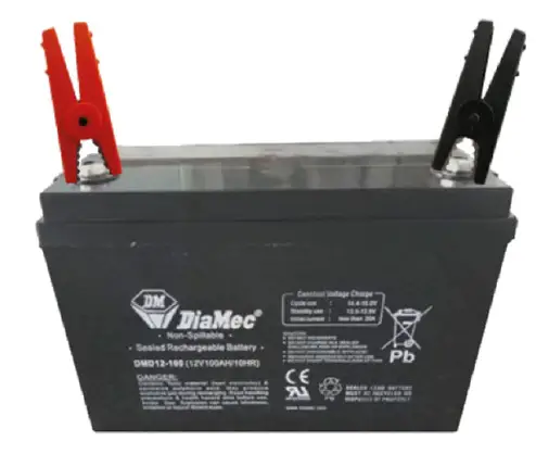
If everything is connected, the IP Monitor will have a Green status light. This will now be available and online in the IP Energiser Controller application.
JVA Distributors
If you have questions or need further assistance, please email us at sales@ jva-fence.com.au or call
| Region | Number |
| Australia | 0731 030 582 |
| South Africa | 0861 782 349 |
| World Wide | +61 731 030 582 |
For more information on our complete range of electric fencing products please see the JVA website at https://www.jva-fence.com.au
Tel : +61 (0)499 000 455 Email : [email protected] www.jva-fence.com


