![]()
UM2197
User manual
life. augmented
UM2197 Electronic Speed Controller for BLDC and PMSM Three Phase Brushless Motor
Electronic speed controller for BLDC and PMSM three-phase brushless motor
Introduction
The STEVAL-ESC001V1 reference design for electronic speed controllers (ESC) for drones fits the entry-level commercial drone designs and drives any three-phase brushless (or PMSM) motor running off 6S LiPo battery packs, or any equivalent DC supply, up to 30 A peak current.
The STEVAL-ESC001V1 lets you spin a motor and its propeller in minutes thanks to STM32 Motor Control Software Development Kit (MCSDK) with the ST Motor profiler (X-CUBE-MCSDK). It implements a sensorless field-oriented controlled (FOC) algorithm with 3-shunt current reading, speed control, and full active braking.
The reference design board can accept commands from a flight control unit through PWM signals; other communication bus interfaces like UART, CAN, and I²C are also available. The reference embeds a battery eliminator circuit working at 5 V, an NTC sensor for temperature measurement, and circuitry for overcurrent/overvoltage protection (OCP/OVP). The compact form factor and current capability render this reference design suitable for electronic speed controllers on small and light unmanned aerial vehicles like professional drones. The X-CUBE-MCSDK software package lets you refine your electronic speed controller design.
They act on the FOC parameters embedded in the STM32 and experiment with the ST motor profiler to retrieve rapidly the motor parameters. The ST sensorless FOC algorithm ensures longer flight times and optimal dynamic performance. The STEVAL-ESC001V1 is designed around the highly efficient, low Rdson STripFET F7 power MOSFETs, the high-performance STM32F303CBT7 microcontroller with Arm ® ® Cortex -M4 core, and the L6398 drivers.
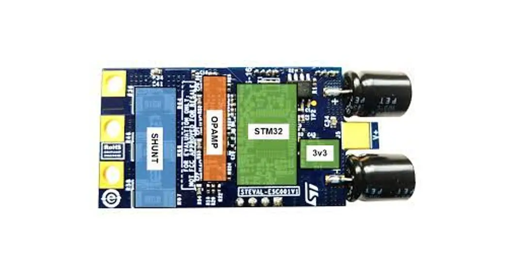
Figure 1. STEVE-ESC001V1 evaluation board
Main features
- Complete reference design for electronic speed controller implementing a sensorless FOC algorithm
- Designed for drones with a 6S pack of LiPo batteries or systems with an equivalent suitable DC supply
- ESC ready for communication with any standard flight control unit (FCU): PWM or CAN
- Temperature overheating protection
- Nominal operating voltage range: 3S-6S Li-Po battery DC voltage level (11.1 to 22.2 V)
- Maximum RMS output current: 20 Arms
- Output peak current: 30 A
- Battery eliminator circuit (BEC): 5 V/0.5 A for an external receiver or FCU
- Example project available on STM32 motor control software development kit (X-CUBE-MCSDK)
- Supported by ST motor control software SDK and ST motor profiler
- Compact PCB design: 29.1 x 58 mm
- Further target applications:
– motor driving for RC vehicles: electric cars, helicopters, trucks, etc.
– any three-phase BLDC or PMSM motor application - RoHS and WEEE compliant
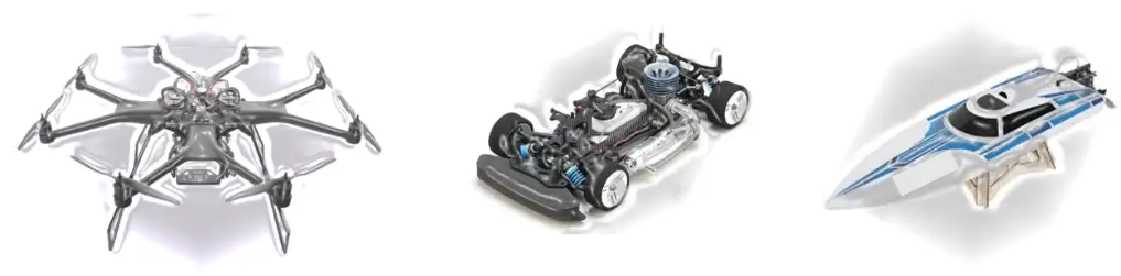
Target application
Motor driving for remote control vehicles, UAV drones, electrical cars, boats, etc.
Figure 2. STEVE-ESC001V1 target applications
Description
The STEVAL-ESC001V1 electronic speed controller (ESC) evaluation board drives a single three-phase brushless motor with very high performance in sensorless mode (without a position sensor). It is designed to provide fast and efficient propulsion for remote control applications like electric cars, boats, and drones and is capable of low and very high-speed regulation and strong dynamic response under different load conditions.
An external signal via a communication bus between the board and a generic central unit sets the speed regulation reference and another signal reports the status of the system, including faults, which the central unit can use to trigger corrective events..
The same 6Step (or trapezoidal) control algorithm (often with no shunt resistors) drives the many different ESCs offering various motor currents, sizes,s, and input voltages for remote control applications. A more sophisticated control algorithm is used in the STEVAL-ESC001V1, based on field-oriented control (FOC); it features:
- better torque control
- motor current regulation in case of fast load change
- vibration reduction
- active braking function
- better efficiency
- noise reduction
- a real-time monitor of the rotor speed
- energy recovery during the deceleration
The typical system architecture pictured below shows individual ESC boards connected to single brushless motors in a quadcopter system. An external Li-Po battery powers the four boards and a wired bus carries communication between each board and an external unit such as a flight control board.
Figure 3. System structure overview
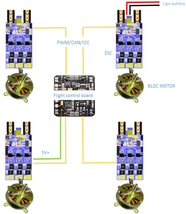
Figure 4. Typical quadcopter architecture
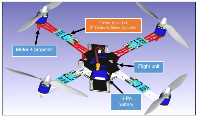
The on-board I²C, UART, PWM, and CAN communication protocols provide maximum flexibility, and a DC-DC converter with a 5 V output connector (BEC) can supply an external control unit or sensor board.
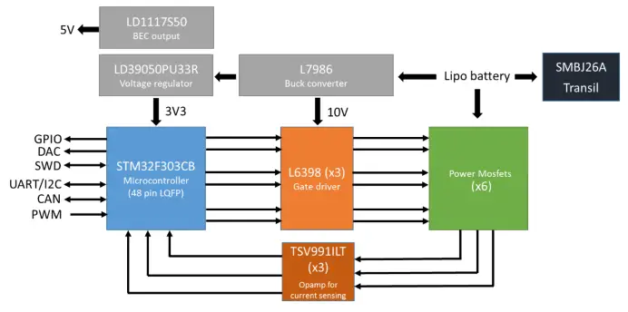
2.1 STEVAL-ESC001V1 hardware overview
The STEVAL-ESC001V1 power and control platform is based on the ST componentry illustrated below.
Figure 5. STEVAL-ESC001V1 block diagram
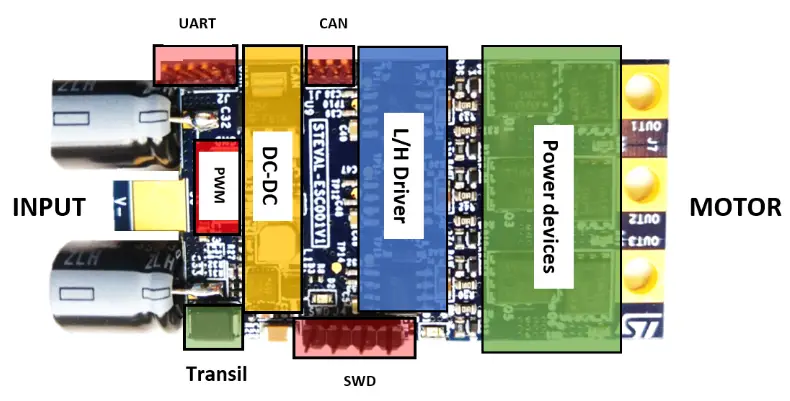
2.1.1 STEVAL-ESC001V1 top side components
The inverter section is formed by the L6398 gate driver and the STL160N4F7 and the Power MOSFETs.
Figure 6. Top side features
L6398 high voltage high and low-side driver
The L6398 is a high voltage device manufactured with the BCD™ “offline” technology. It is a single-chip half-bridge gate driver for the N-channel power MOSFET or IGBT.
The high-side (floating) section is designed to stand a voltage rail up to 600 V. The logic inputs are CMOS/TTL compatible down to 3.3 V for the easy interfacing microcontroller/DSP. Key features:
- High voltage rail up to 600 V
- DV/DT immunity ±50 V/ns in the full temperature range
- Driver current capability:
– 290 mA source
– 430 mA sink - Switching times 75/35 ns rise/fall with 1 nF load
- 3.3 V, 5 V TTL/CMOS input comparators with hysteresis
- Integrated bootstrap diode
- Fixed 320 ns deadtime
- Interlocking function
- Compact and simplified layout
- Bill of material reduction
- Flexible, easy, and fast design
STL160N4F7 160 A STripFET™ F7 Power MOSFETs
This N-channel Power MOSFET uses STripFET™ F7 technology with an enhanced trench gate structure that results in very low on-state resistance, while also reducing internal capacitance and gate charge for faster and more efficient switching.
L7986, LD1117S50, and LD39050PU33R
These devices provide the appropriate voltage for gate driving, BEC output, and MCU power.
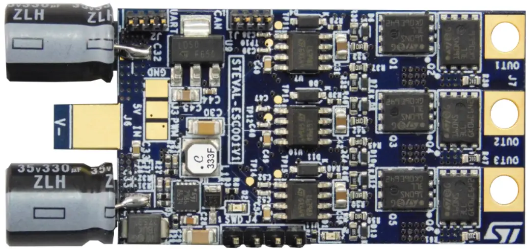
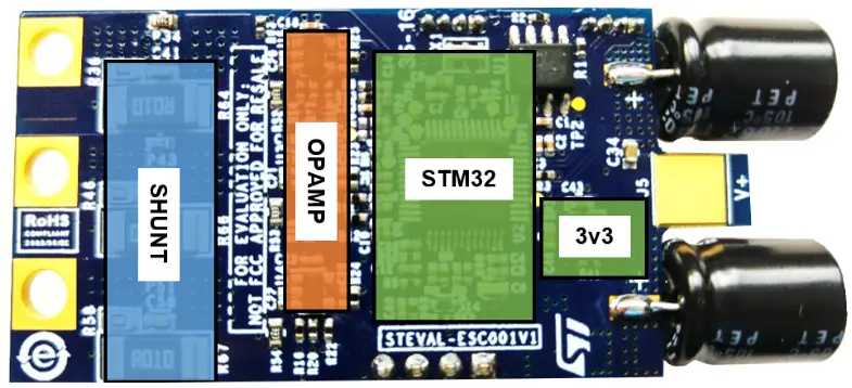
2.1.2 STEVAL-ESC001V1 bottom side components
The bottom side componentry is mainly for the digital section; featuring an STM32F303 microcontroller for three-shunt sensorless FOC control in an LQFP 48-pin package.
STM32F303xB 32-bit ARM Cortex-M4 MCU with 128 Kbytes Flash and 72 MHz CPU
The family of microcontrollers is based on the high-performance ARM ® ®Cortex -M4 32-bit RISC core plus FPU operating at 72 MHz max and embedded memory protection unit (MPU).
Figure 7. Bottom side features
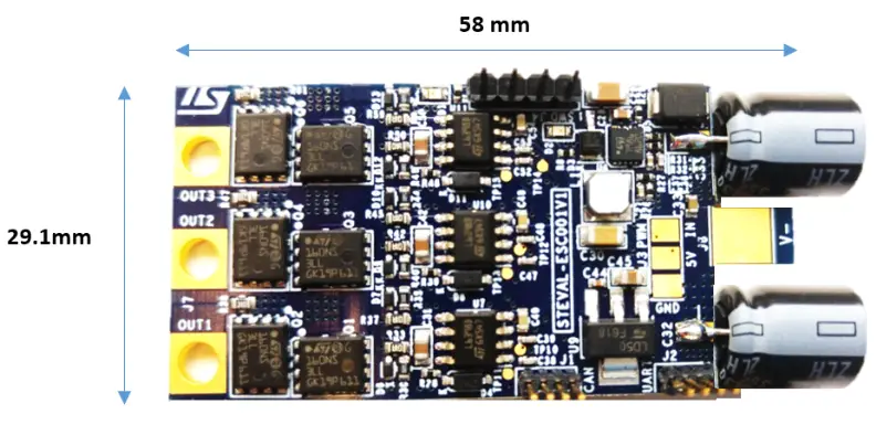
2.1.3 Board dimensions (29.1 x 58 mm)
Figure 8. STEVE-ESC001V1 board dimensions (not including capacitors)
2.2 Communication, programming, and command interfaces
The STEVAL-ESC001V1 features these communication interfaces:
- CAN port (J1): comes with an onboard transceiver; the J1 connector includes 3V3 and GND pins.
- UART/I²C port (J2): normally used for serial communication between the ESC board and a PC; ST MC Workbench can be connected with the STM32, adding an external circuit (requires USB/RS232 converter-3v3 level)
Figure 9. UART TX/RX (3v3 level)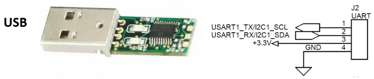
- PWM signal input (J3): connects with an external board (e.g., flight control unit), to receive commands; the signal level (at 3v3) sets the motor speed according to the Ton duration (i.e., 1060 µs for min. speed and 1860 µs for max. speed). Other pins are for GND and a +5Vdc power line to supply an external board
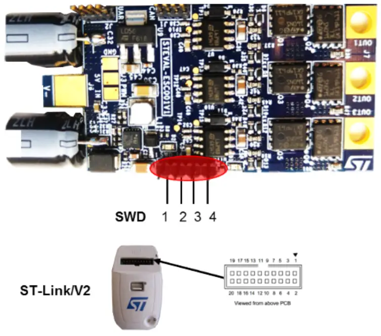
- SWD debug port (J4): provides the SWD connection between the STM32 and ST-LINK programmer; other pins like 3V3 and GND are available.
2.3 STM32 pinout for motor control
Table 1. Main STM32 pinout for motor control
| Pin | Default | Signal | Solder Bridge |
| 1 | VBA | 3V3 | |
| 2 | PC13/TAMP/RTC | TP4 | |
| 3 | PC14 | N.C. | |
| 4 | PC15 | N.C. | |
| 5 | PF0/OSC-IN | OSC 8Mhz | |
| 6 | PF1/OSC-OUT | OSC 8Mhz | R4 |
| 7 | NRST | RESET | |
| 8 | VSSA/VREF- | GND | |
| 9 | VDDA/VREF+ | 3V3 | |
| 10 | PA0-WKUP | Curr_fdbk1 | |
| 11 | PA1 | Curr_fdbk2 | |
| 12 | PA2 | Curr_fdbk3 | |
| 13 | PA3 | Temperature feedback | |
| 14 | PA4 | VREF, DAC1, TP8 | R6 N.M. |
| 15 | PA5 | DAC2, TP9 | |
| 16 | PA6 | N.C. | |
| 17 | PA7 | Vshunt_1_filtered | |
| 18 | PB0 | Vshunt_2_filtered | |
| 19 | PB1 | TIM1_CH3N | |
| 20 | PB2 | STATUS | |
| 21 | PB10 | N.C. | |
| 22 | PB11 | Vshunt_3_filtered | |
| 23 | VSS1 | GND | |
| 24 | VDD1 | 3V3 | |
| 25 | PB12 | PHASE_1 | R5 |
| 26 | PB13 | VBUS | |
| 27 | PB14 | PHASE_2 | |
| 28 | PB15 | PHASE_3 | |
| 29 | PA8 | TIM1_CH1 | |
| 30 | PA9 | TIM1_CH2 | |
| 31 | PA10 | TIM1_CH3 | R51 |
| 32 | PA11 | TIM1_CH1N | |
| 33 | PA12 | TIM1_CH2N | |
| 34 | PA13 | STUDIO | |
| 35 | VSS2 | GND | |
| 36 | VDD2 | 3V3 | |
| 37 | PA14 | SWCLK | |
| 38 | PA15 | INPUT | |
| 39 | PB3 | N.C. | |
| 40 | PB4 | TP3 | |
| 41 | PB5 | N.C. | |
| 42 | PB6 | USART1_TX/I2C1_SCL | |
| 43 | PB7 | USART1_RX/I2C1_SDA | |
| 44 | BOOT0 | BOOT0 | R3 |
| Pin | Default | Signal | Solder Bridge |
| 45 | PB8 | CAN_RX | |
| 46 | PB9 | CAN_TX | |
| 47 | VSS | ||
| 48 | VDD |
Table 2. Input/output terminals
| Screw Terminal | Function |
| J5/J6 | Li-Po battery power input (3S-6S) |
| J7 | 3-PH Motor connector |
Initializing and using the STEVAL-ESC001V1 ESC board
Step 1. Connect the ST-LINK/V2 programmer to the J4 connector on the board.
Table 3. Relationship between the STEVAL board SWD pinout and SWD on ST-Link/V2 programmer
| Pin no. in STLINK | ST-LINK/V2 | ST-LINK/V2 function | Target connection | Pin no. in STEVALESC001V1 (J4 connector) |
| 1 | connector | Target VCC | (SWD) | 1 |
| 2 | VAPE | Target VCC | MCU VDD | 1 |
| 6 | VAPE | 4 | ||
| 7 | GND | SW IO | STUDIO | 3 |
| 9 | SW CLK | SWCLK | 2 |
Figure 10. STEVAL-ESC001V1 connection for MCU programming
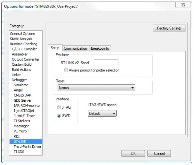
Step 2. Set the SWD interface in the IDE tool.
Figure 11. Sample SWD configuration on the IAR tool
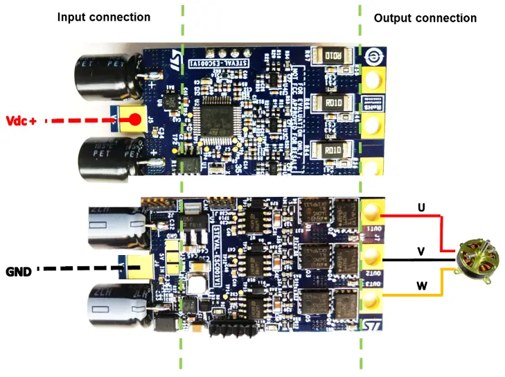
Step 3. Solder the three motor wires U, V, and W at the motor connector with no particular color sequence. As shown in Figure 12. STEVAL-ESC001V1 input/output connection, the right side is for the motor connection with three pads provided for soldering.
Step 4. Solder the PWM input at the J3 connector. The INPUT pin level must not exceed 3V3.
Step 5. Connect the STEVAL-ESC001V1 with a Li-Po battery (or DC power supply: min 3S – max 6S) with the right polarity and turn it ON. The input connector has two large pads for soldering: the top layer for GND and the bottom for Vdc+. A transit device prevents damage in case of reverse polarity.
Step 6. Verify if the green led is turned on.
Step 7. Open ST ST Motor Control Workbench.
Figure 13. ST MC Workbench
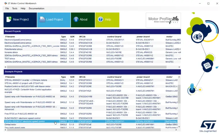
Step 8. Follow the instructions included in the readme file to compile/upload the example project.
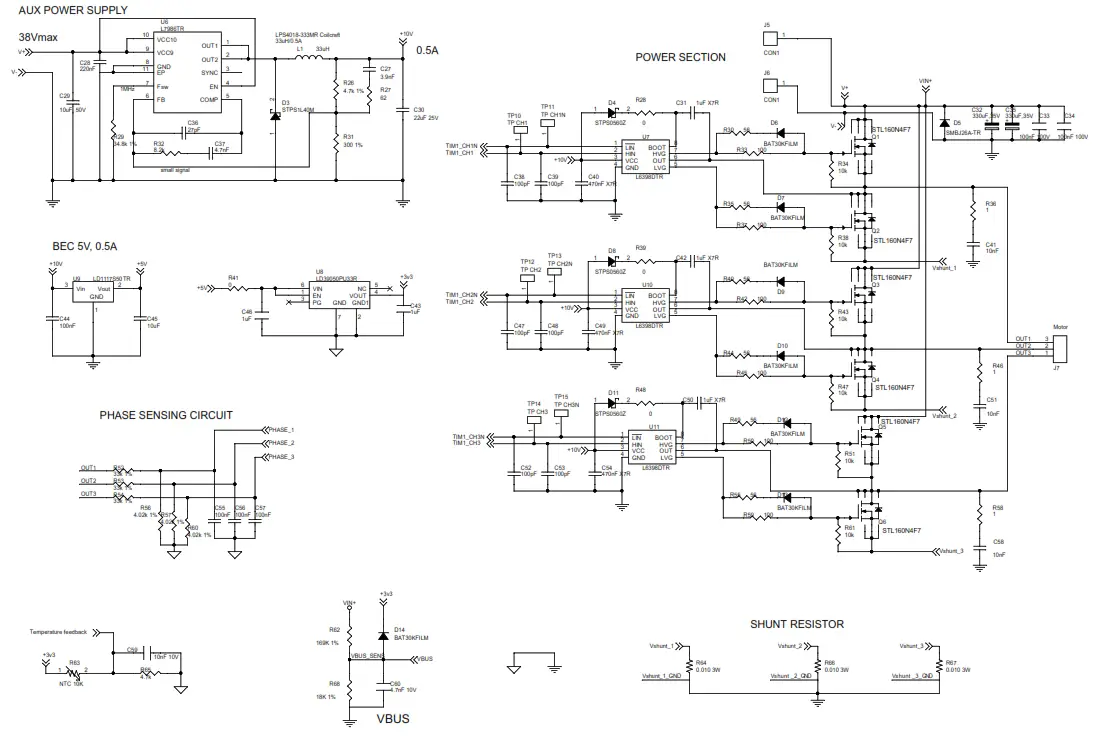
Schematic diagrams
Figure 14. STEVAL-ESC001V1 circuit schematic (1 of 4)
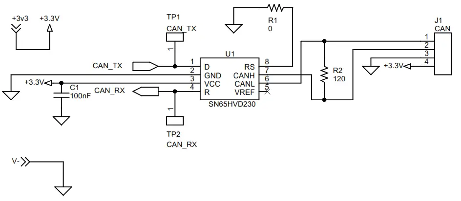
Figure 15. STEVAL-ESC001V1 circuit schematic (2 of 4)
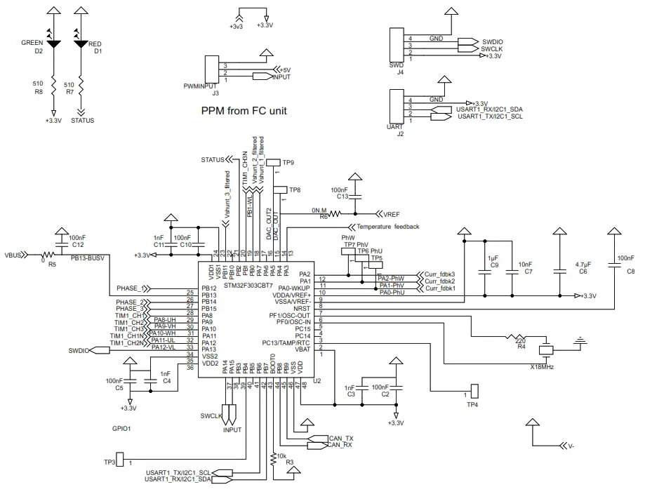
Figure 16. STEVAL-ESC001V1 circuit schematic (3 of 4)
For internal comparator
OCP circuit
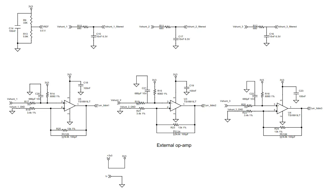
Figure 17. STEVAL-ESC001V1 circuit schematic (4 of 4)
| Item | Q.ty | Ref. | Part / Value | Description | Manufacturer | Order code |
| 1 | 15 | C1, C2, C5, C8, C10 C12, C13, C14, C18 C19, C23, C44, C55 C56, C57 | 100 nF 25 V ±10% X7R | Ceramic capacitor | any | |
| 2 | 3 | C3, C4, C11 | 1 nF 50 V ±10% X7R | Ceramic capacitor | any | |
| 3 | 1 | C6 | 4.7 µF 10 V ±10% X5R | Ceramic capacitor | Murata | GRM188R61A475KE15D |
| 4 | 2 | C7, C59 | 10 nF 50 V ±10% X7R | Ceramic capacitor | any | |
| 5 | 3 | C9, C43, C46 | 1 µF 16 V ±10% X7R | Ceramic capacitor | TDK | C1608X7R1C105K080AC |
| 6 | 3 | C15, C16, C17 | 15 nF 10 V ±10% X7R | Ceramic capacitor | any | |
| 7 | 3 | C20, C21, C22 | 680 pF 10 V ±5% C0G | Ceramic capacitor | any | |
| 8 | 3 | C24, C25, C26 | 100 pF ±0% | Capacitors (not | ||
| 9 | 1 | C27 | 3.9 nF 50 V ±10% X7R | Ceramic capacitor | any | |
| 10 | 1 | C28 | 220 nF 50 V ±10% X7R | Ceramic capacitor | any | |
| 11 | 1 | C29 | 10 µF 50 V ±10% X5R | Ceramic capacitor | any | |
| 12 | 1 | C30 | 1 µF X7R 50 V ±10% | Ceramic capacitor | any | |
| 13 | 3 | C31, C42, C50 | 330 µF,35 V ±20% | Ceramic capacitor | any | |
| 14 | 2 | C32, C35 | 100 nF 100 V ±10% X7R | Electrolytic capacitor | Rubycon | 35ZLH330MEFC10X12.5 |
| 15 | 2 | C33, C34 | 27 pF 50 V ±5% C0G | Ceramic capacitor | any | |
| 16 | 1 | C36 | 4.7 nF 16 V ±10% X7R | Ceramic capacitor | any | |
| 17 | 2 | C37, C60 | 100 pF 16 V ±10% X7R | Ceramic capacitor | any | |
| 18 | 6 | C38, C39, C47 | 470 nF 25 V ±10% X7R | Ceramic capacitor | any | |
| 19 | 3 | C40, C49, C54 | 10 nF 100 V ±10% X7R | Ceramic capacitor | any | |
| 20 | 3 | C41, C51, C58 | 10 µF 25 V ±10% X7R | Ceramic capacitor | any | GRM21BR61E106KA73L |
| 21 | 1 | C45 | 10 µF 25 V ±10% X7R | Ceramic capacitor | Murata | LTST-C193KRKT-5A |
| 22 | 1 | D1 | Red LED | Lite-on | LTST-C193KGKT-5A | |
| 23 | 1 | D2 | Red LED | Lite-on | ||
| 24 | 1 | D3 | 40 V 1 A | Low drop power Schottky diode | ST | STPS1L40M |
| 25 | 3 | D4, D8, D11 | 60V/0.5A | Power Schottky diode | ST | STPS0560Z |
| 26 | 1 | D5 | Trans | ST | SMBJ26A-TR | |
| 27 | 7 | D6, D7, D9, D10 D12, D13, D14 | 30V, 0.3A | Schottky diode | ST | BAT30KFILM |
| 28 | 2 | J1, J2 | CAN, UART: 4 WAYS STRIP LINE – MALE 1.27mm | any | ||
| 29 | 1 | J3 | PWM INPUT: 3 way wires welding | any | ||
| 30 | 1 | J4 | SWD: 4-way strip line – male 2.54mm | |||
| 31 | 2 | J5, J6 | CON1 – Input power connector: 1-way wire welding | |||
| 32 | 1 | J7 | Motor Connector: 3way wire welding | |||
| 33 | 1 | L1 | 33 µH 0.5 A | Power inductor | Coilcraft | LPS4018-333MRB |
| 34 | 6 | Q1, Q2, Q3 Q4, Q5, Q6 | 30 V, 160 A 40 V, 160 A | Power MOSFETs | ST | STL160NS3LLH7 STL160N4F7 |
| 35 | 6 | R1, R5, R28 R39, R41, R48 | 0 62.5 mW ±5% | SMD resistor | any | |
| 36 | 1 | R2 | 120 62.5 mW ±5% | SMD resistor | any | |
| 37 | 1 | R3 | 10 k 62.5 mW ±5% S | SMD resistor | any | |
| 38 | 1 | R4 | 220 62.5 mW ±5% | SMD resistor | any | |
| 39 | 1 | R6 | 62.5 mW ±5% | SMD resistor | any | |
| 40 | 2 | R2 R2 | 510 62.5 mW ±5% | SMD resistor | any | |
| 41 | 1 | R9 | 33 K 62.5 mW ±5% | SMD resistor | any | |
| 42 | 3 | R10, R11, R12 | 680 62.5 mW ±5% | SMD resistor | any | |
| 43 | 1 | 5.9 K 62.5 mW ±5% | SMD resistor | any | ||
| 44 | 3 | R14, R15, R16 | 8.06 k 62.5 mW ±1% | SMD resistor | Panasonic | CRCW04028K06FKED |
| 45 | 3 | R17, R19, R20 | 787 62.5 mW ±1% | SMD resistor | Panasonic | ERJ2RKF7870X |
| 46 | 3 | R18, R21, R22 | 4 k 62.5 mW ±1% | SMD resistor | any | ERJ2RKF3401X |
| 47 | 2 | R23, R24, R25 | 13 k 62.5 mW ±1% | SMD resistor | any | |
| 48 | 1 | R26 | 4.7 k 62.5 mW ±1% | SMD resistor | any | |
| 49 | 1 | R65 | 4.7 k 62.5 mW ±5% | SMD resistor | any | |
| 50 | 1 | R27 | 4.7 k 62.5 mW ±5% | SMD resistor | any | |
| 51 | 6 | R29 | 62 62.5 mW ±1% | SMD resistor | any | |
| 52 | 1 | R30, R35, R40 R44, R49, R55 | 34.8 k 62.5 mW ±1% | SMD resistor | any | |
| 53 | 1 | R31 | 56 0.1 W ±5% | SMD resistor | any | |
| 55 | 6 | R32 | 300 62.5 mW ±1% | SMD resistor | any | |
| 56 | 6 | R33, R37, R42 R45, R50, R59 | 8.2 k 62.5 mW ±1% | SMD resistor | any | |
| 57 | 3 | R34, R38, R43 R47, R51, R61 | 100 0.1 W ±5% | SMD resistor | any | |
| 58 | 3 | R36, R46, R58 | 10 k 0.1 W ±5% | SMD resistor | any | |
| 59 | 1 | R52, R53, R54 | 4.02 k 62.5 mW ±1% | SMD resistor | any | |
| 60 | 1 | R56, R57, R60 | 169 K 62.5 mW ±1% | SMD resistor | any | |
| 61 | 1 | R63 | NTC 10 K ±1% | NTC Thermistor | TDK | NTCG103JF103F |
| 62 | 3 | R64, R66, R67 | 0.01 3 W ±1% | 10 mOhm shunt resistor | Bourns KOA Speer | CRA2512-FZ-R010ELF TLR3APDTE10L0F50 |
| 63 | 1 | R68 | 18 K 62.5 mW ±1% | SMD resistor | any | |
| 64 | 1 | TP1, TP2, TP3, TP4 TP5, TP6, TP7, TP8 TP9, TP10, TP11 TP12, TP13, TP14 TP15 | SMD PAD 1 mm ±0% | Test point | any | |
| 65 | 1 | U1 | CAN transceiver | TI | SN65HVD230D | |
| 66 | 1 | U2 | 32bit MCU | ST | STM32F303CBT7 | |
| 67 | 1 | U3, U4, U5 | Rail-to-rail input/ output 20 MHz GBP operational amplifiers | ST | TSV991ILT | |
| 68 | 3 | U6 | 3 A step-down switching regulator | ST | L7986TR | |
| 69 | 1 | U7, U10, U11 | High voltage high and low-side driver | ST | L6398D | |
| 70 | 3 | U8 | Low drop voltage regulator | ST | LD39050PU33R | |
| 71 | 1 | U9 | Low drop voltage regulator | ST | LD1117S50TR | |
| 72 | 1 | X1 | Resonators 8 Mhz | Murata | CSTCE8M00G55-R0 | |
Revision history
Table 5. Document revision history
| Date | Version | Changes |
| 7-Apr-2017 | 1 | Initial release. |
| 13-Nov- 2018 | 2 | Updated Introduction and Section 5 Bill of materials. Added references to STL160N4F7. |
| 10-Nov-2021 | 3 | Updated Introduction, Section 1 Main features, and Section 3 Initializing and using the STEVALESC001V1 ESC board. |
IMPORTANT NOTICE – PLEASE READ CAREFULLY
STMicroelectronics NV and its subsidiaries (“ST”) reserve the right to make changes, corrections, enhancements, modifications, and improvements to ST products and/or to this document at any time without notice. Purchasers should obtain the latest relevant information on ST products before placing orders. ST products are sold pursuant to ST’s terms and conditions of sale in place at the time of order acknowledgment. Purchasers are solely responsible for the choice, selection, and use of ST products and ST assumes no liability for application assistance or the design of Purchasers’ products. No license, express or implied, to any intellectual property right is granted by ST herein. Resale of ST products with provisions different from the information set forth herein shall void any warranty granted by ST for such product. ST and the ST logo are trademarks of ST. For additional information about ST trademarks, please refer to www.st.com/trademarks. All other product or service names are the property of their respective owners. Information in this document supersedes and replaces information previously supplied in any prior versions of this document.
© 2021 STMicroelectronics – All rights reserved
References
 STMicroelectronics: Our technology starts with you
-
STMicroelectronics Trademark List - STMicroelectronics
-
BAT30 - 30 V, 300 mA SMD General purpose Signal Schottky Diode - STMicroelectronics
-
L6398 - High voltage high and low-side driver - STMicroelectronics
-
L7986 - 3 A step-down switching regulator - STMicroelectronics
-
LD1117 - Adjustable and fixed low drop positive voltage regulator - STMicroelectronics
-
LD39050 - 500 mA low quiescent current and low noise voltage regulator - STMicroelectronics
-
STEVAL-ESC001V1 - Electronic speed controller reference design for drones - STMicroelectronics
-
STL160N4F7 - N-channel 40 V, 2.1 mOhm typ., 120 A STripFET F7 Power MOSFET in a PowerFLAT 5x6 package - STMicroelectronics
-
STM32F303CB - Mainstream Mixed signals MCUs Arm Cortex-M4 core with DSP and FPU, 128 Kbytes of Flash memory, 72 MHz CPU, MPU, CCM, 12-bit ADC 5 MSPS, PGA, comparators - STMicroelectronics
-
STPS0560Z - 60 V, 0.5 A Power Schottky Rectifier - STMicroelectronics
-
STPS1L40M - 40 V, 1 A STmite Low Drop Power Schottky Rectifier - STMicroelectronics
-
TSV991 - Wide-bandwidth (20MHz) rail to rail input/output 5V CMOS Op-Amp, single - STMicroelectronics
-
X-CUBE-MCSDK - STM32 Motor Control Software Development Kit (MCSDK) - STMicroelectronics


