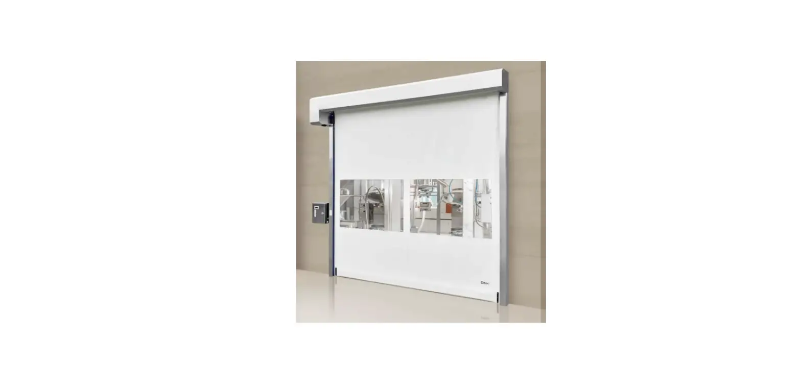
Ditec 0DT872 Soft Reset Food
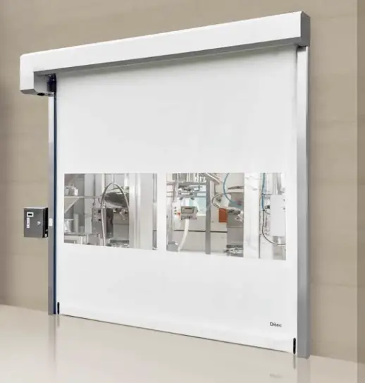
Ditec Soft Reset Food is an industrial door system designed to provide secure and reliable access control to food processing facilities. The system is equipped with a motor that opens and closes the door, as well as safety features such as SLE (primary safety) and 52E (emergency stop) connections.
Product Usage Instructions
- Mount the system to the ground using the instructions provided in section 3.2 of the installation manual.
- Attach the door to the system using the instructions provided in section 3.3 of the installation manual.
- Install the door shutter by following the instructions provided in section 3.6 of the installation manual.
- Install the column casing by following the instructions provided in section 3.7 of the installation manual.
- Connect the motor using the instructions provided in section 4.1 of the installation manual.
- Connect the SLE (primary safety) using the instructions provided in section 4.2 of the installation manual.
- Connect the 52E (emergency stop) using the instructions provided in section 5.1 of the installation manual.
- Use the programming menu as per section 6 of the installation manual to set up and adjust various settings such as interlocking and service mode.
- If any malfunctions occur, refer to section 7 of the installation manual for troubleshooting guidance.
- Regularly maintain the system as described in section 9 of the installation manual to ensure proper functioning.
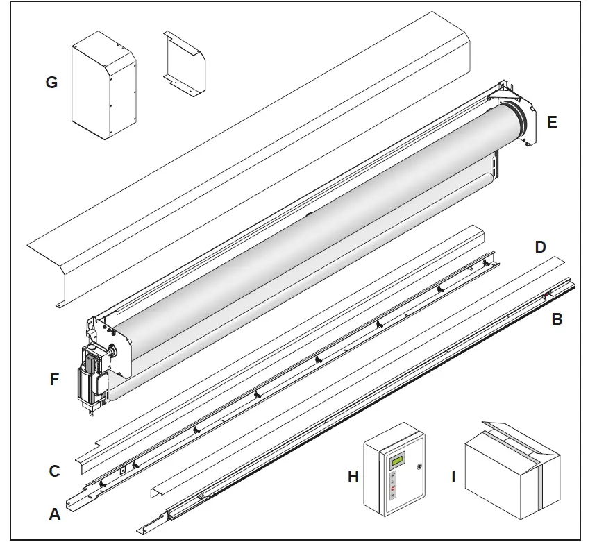
PACKING LIST
| Reference | Description | Quantity |
| A | Left column | 1 |
| B | Right column | 1 |
| C | Left Cover | 1 |
| D | Right Cover | 1 |
| E | Transom with rolled curtain | 1 |
| F | K22 Motor | 1 |
| G | Motor carter and opposite side plate cover | 1 |
| H | Control unit | 1 |
| I | Hardware box | 1 |
GENERAL SAFETY PRECAUTIONS
- This installation manual is intended for professionally competent personnel only.
- The installation, the electrical connections and the settings must be completed in conformity with good workmanship and with the laaws in force.
- Read the instructions carefully before beginning to install the product. Incorrect installation may be a source of danger. Packaging materials (plastics, polystyrene, etc) must not be allowed to litter the environment and must be kept out of the reach of children for whom they may be a source of danger. Before beginning the installation check that the product is in perfect condition.
- Do not install the product in explosive areas and atmospheres: the presence of flammable gas or fumes represents a serious threat to safety.
- Before installing the door, make all the structural modifications necessary in order to create safety clerance and to guard or isolate all the compression, shearing, trapping and general danger areas.
- Check that the existing structure has the necessary strength and stability.
- The safety devices must protect against compression, shearing, trapping and general danger areas of the motorized door.
- Display the signs required by law to identify danger areas. Each installation must bear a visible indication of the data identifying the motorized door.
- Before connecting to the mains check that the rating is correct for the destination power requirements.
- A multipolar isolation switch with minimum contact gaps of 3 mm must be included in the mains supply.
- Check that upstream of the electrical installation there is an adequate differential switch and a suitable circuit breaker. Ensure that the motorized door has an earth terminal in accordance with the safety adjustments in force.
- The manufacturer of the door declines all responsibility in cases where components that are incompatible with the safe and correct operation of the product only original spare parts must be used or whenever modifications of any nature are made that have not been specifically authorized by the manufacturer.
- For repairs or replacements of products, only Ditec original spare parts must be used.
- The fitter must supply all information concerning the automatic, manual and emergency operation of the motorized door or gate, and must provide the user the device with the operating instructions.
All right reserved
All data and specifications have been drawn up and checked with the greatest care. The manufacturer cannot however take any responsibility for eventual errors, ommisions or incomplete data due to technical or illustrative purposes.
Description
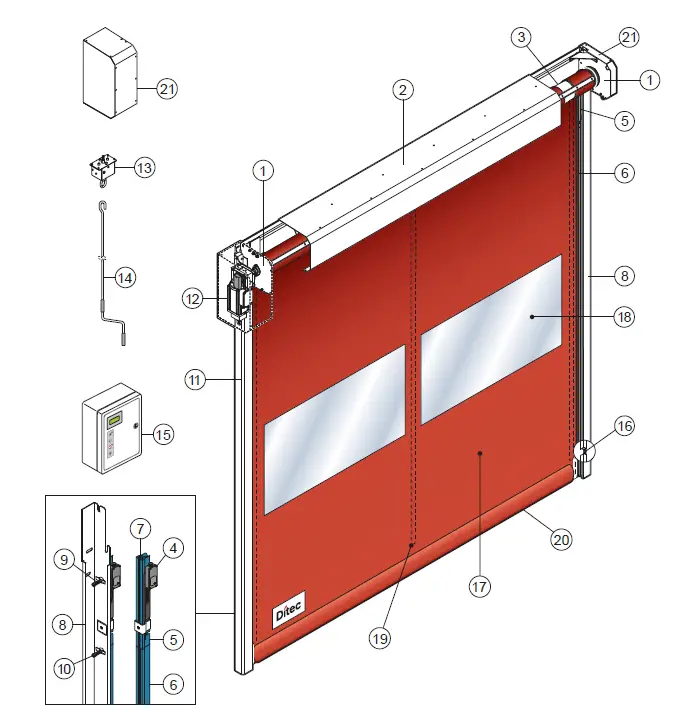
- Lateral plate of the transom
- Transom
- Rolling shaft
- Linear Encoder (SLE)
- Polyzene guide upper section
- Polyzene guide lower section
- Fixing plate of the guide
- Angular vertical post
- Supporting spring
- Fixing screw
- Column cover
- Geared motor K22
- Manual driving device
- Manual driving rod
- Electronic board
- Photocell
- Polyester curtain
- PVC transparent window
- Vertical re reinforcing strips
- Bottom edge with sand ballast
- Motor carter and opposite side plate co
TECHNICAL CHARACTERISTICS
CONTROL PANEL INVERTER (52E)
- Power supply voltage …………………………………………………………………………………………………….. 230 V monofase 50/60 Hz
- Line sizing ……………………………………………………………………………………………………………………………………………….16 A
- Auxiliary control power voltage……………………………………………………………………………………………………………………24V
- Motor rating……………………………………………………………………………………………………………………………………………….0,6 KW
- Control board protection class………………………………………………………………………………………………………………………… IP 66
- Operating temperature………………………………………………………………………………………………………………………….. – 5 + 50 °C
Correctly size the line conductor cross-section by referring to the indicated absorption and taking the length and installation of the cables into account
MECHANICAL INSTALLATION
See the relevant drawings of the mechanical installation at page. 23 – 24 -25 – 26 (central sheet to be removed).
Check of the opening (fig.1).
- Check the dimensions of the opening and their correspondence to the overall dimensions of the door supplied, taking into consideration any necessary tolerances in the case of installation in an archway.
- Check that no existing structures obstruct the assembly of the door.
- Ensure the resting surfaces are level and, if necessary, adapt them using appropriate shims.
- Check the solidity of the opening: secure anchorage must be ensured by means of brackets or anchor plugs. In the case of insufficient or dubious solidity, it is necessary to create an adequate self-supporting metal structure.
Assembly on the floor (fig.2)
- Place crosspiece and columns on the floor, fix columns to the crosspiece with M8 self-locking nuts (A) through the threaded inserts (B) present on the side plate.
Door fixing (fig.4)
- Lift the door and place it on the opening (fig.3).
- Check the verticality of the columns and fix them in the indicated points (C). Anchor plug dimension M8 (D).
- Drill in the center of the slotted holes (C).
- Check the perpendicularity of the assembly by measuring the diagonals
Gear motor K22 (fig.5)
- Adjust the silent blocks (E) to get the motor in a vertical position (the silent blocks must result slightly compressed on the rear wall).
- After adjustment, lock the silent blocks with the nut (F).
- For manual operation (if foreseen), insert the device following the indications (fig.6).
- Connect the micro-contact by observing the relevant diagram and check it functions correctly: the micro-contact must cut off motor rotation when manual operation is activated
Installation of the safety device SLE (Safety Linear Encoder)
The SLE must be fixed to the sliding guide of the flexible door, on motor side, as shown in (fig.7) and connected as shown at paragraph 5.
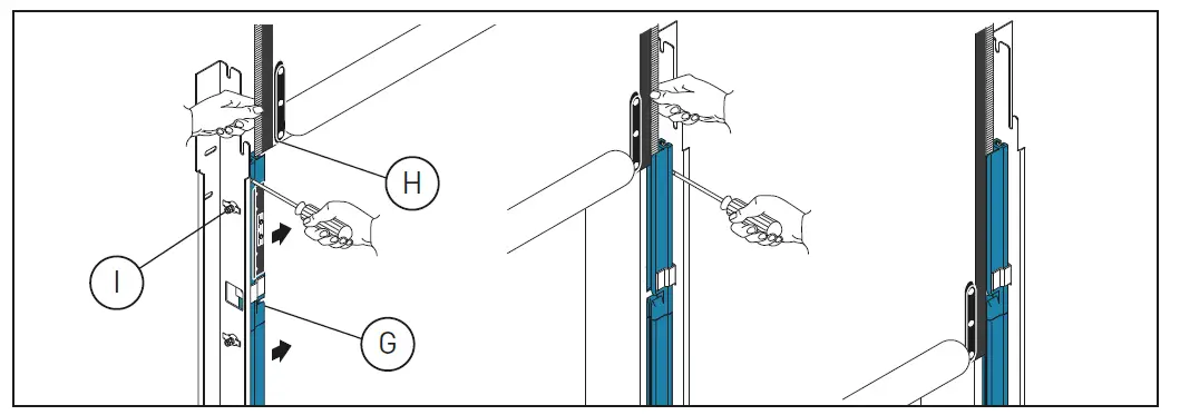
Curtain positioning
- Move the guide (G) inward by pushing the outer side (fig.8).
- Insert each tooth of the curtain side edge (H) in the relevant guide; to make easier the operation remove the higher screw (I).
- Roll down the curtain so the bottom edge is 0,5 m beneath the curtain inlet slot (fig.8).
Column cover fixing
- Galvanized door; place the cover on to the edge (1) of the column and click it on the edge (2) (fig.9A).
- Stainless steel door; fix the covers with M4 screws (fig.9B).
Motor and side plate cover fixing
- Fix the top of motor cover to the side plate with M6 screw (L) and the side with M8 screws (M) (fig. 10).
- Fix the side plate cover, inside, with screws M6x16 (O) (fig.11).
Transom cover fixing
- Fix transom cover with screws M6x16 (N) (fig.11).
ELECTRICAL CONNECTIONS
The supplied cablings don’t provide any intermediate connection, but they directly connect each device to the control board.
MOTOR CONNECTION
CONTROL BOARD SIDE: insert the two cablings for motor and brake (code 9635), through the cable glands 4 and 3 (fig.11). Insert the thermal protection cable through the cable gland 7. Fit the connectors on the control board as shown at par. 5.1.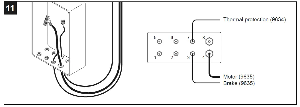
MOTOR SIDE: open the junction box, disconnect and remove the cablings 4327 and 9029 (fig. 12). Drill a hole Ø9 on the box (fig. 13) and insert the grommet, present on the cabling 9634. Insert the cablings 9634 and 9635 and connect to the terminals as shown at par.5.1. Connect the cable with ring nut to the encoder (fig.14).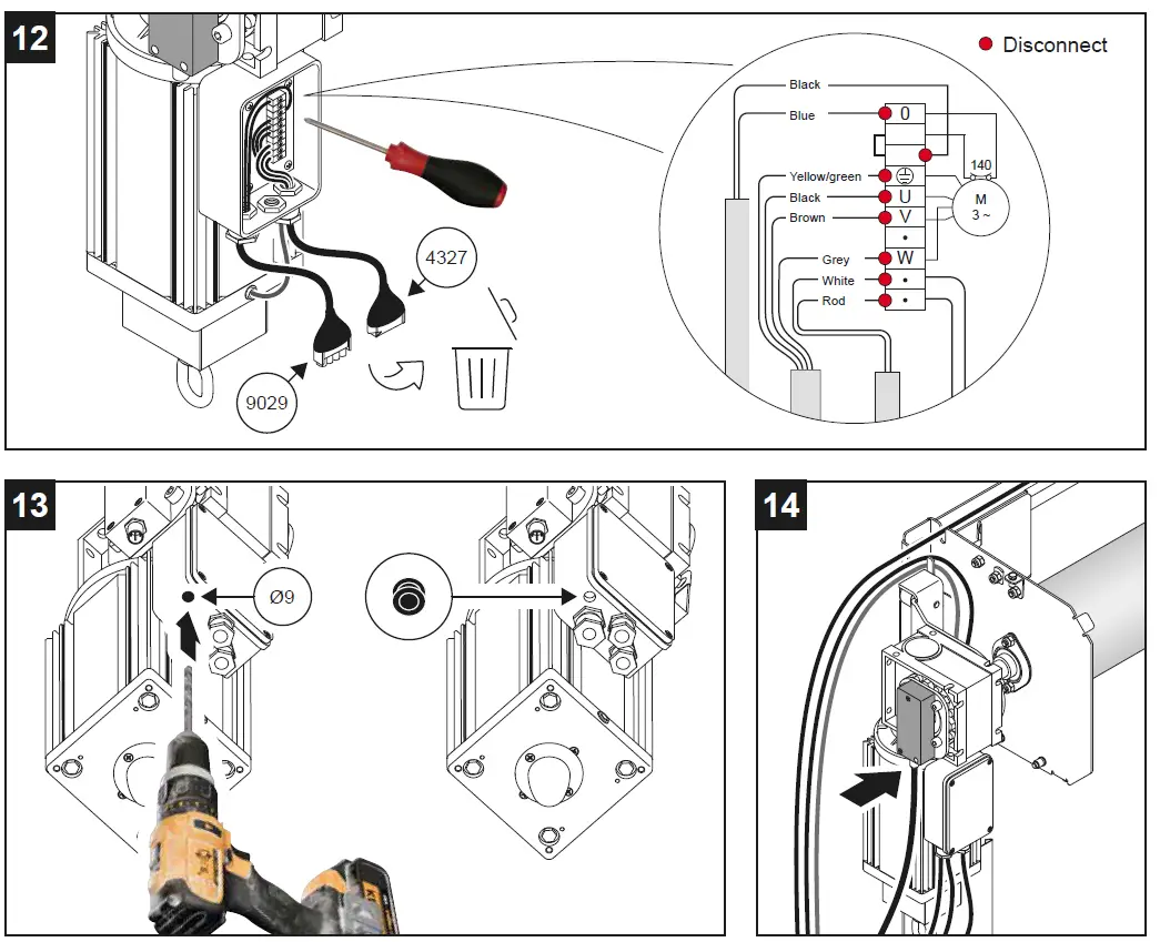
SLE CONNECTION (PRIMARY SAFETY)
Disconnect and remove from the SLE the cabling 9016. Insert the cabling 8457 and fit the connector on the SLE PCB (fig.15).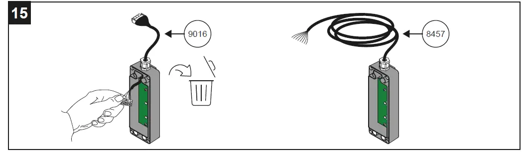
CONNECTIONS TO THE CONTROL BOARD
Insert the cablings through the relevant cable glands:
- Encoder – cable gland 1
- SLE (8457) – cablegland 2
- Photocells – cable glands 5 e 6
- Power supply (not provided) – cable gland 8
Connect all the cablings to the control board as shown at par. 5.1. In the event that the door is subject to washing, it is preferable not to insert the cables into closed conduits (pipes or others) to avoid water stagnation, but provide open supports to house the cables. Fig.16 schematically shows the wiring supplied and their positioning.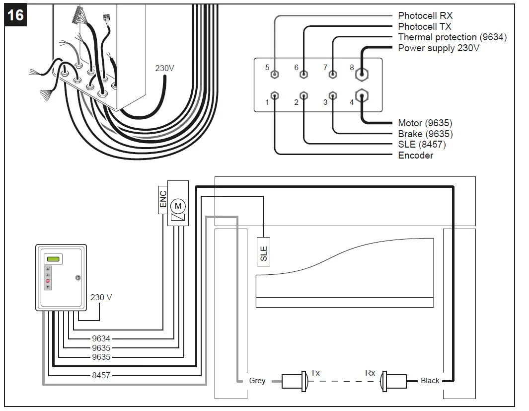
Correctly size the line conductor cross-section by referring to the indicated absorption and taking the length and installation of the cables into account.
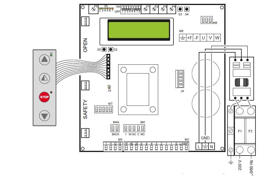
52E CONTROL PANEL (INVERTER) – Connections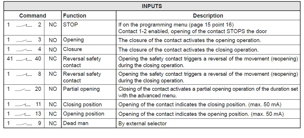
CONTROL PANEL CONNECTORS
| M2 | Safety device / Commands |
| M3 | Position signal |
| M4 | Interlock |
| M4A | Back |
| M5 | Motor / brake motor |
| M6 | Thermal motor |
| M7 | Absolute encoder |
| J4 | Brake resistance |
| OPEN | Auxiliary panel card |
| SAFETY | Auxiliary safety card |
OUTPUTS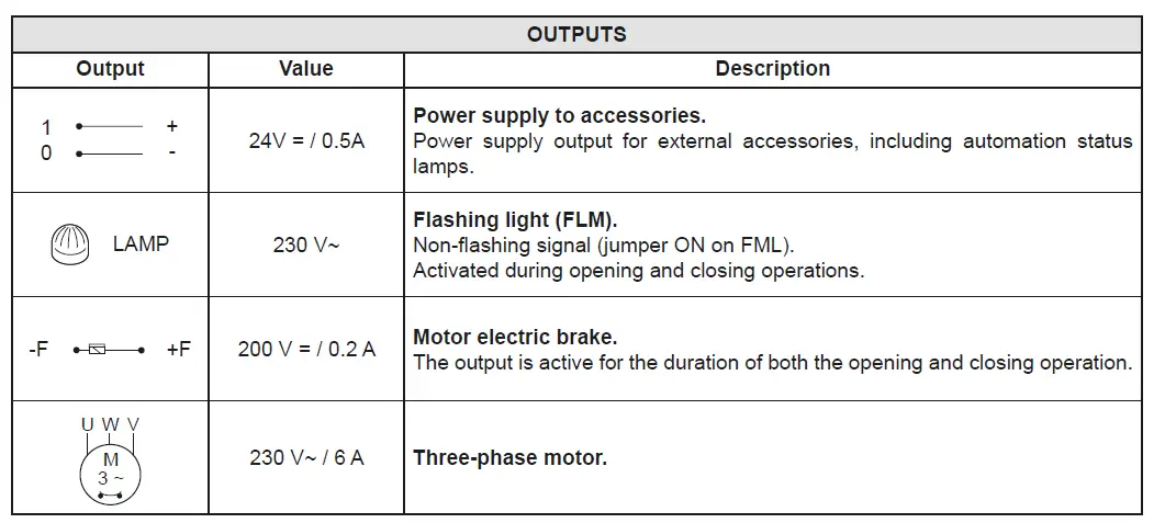
When the absolute encoder wiring is disconnected, the positions of the limit switches are reset.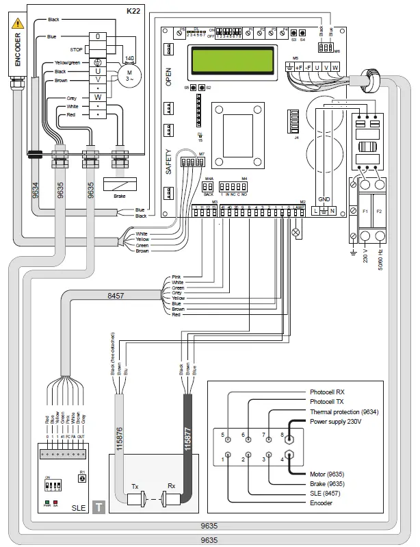
When the absolute encoder wiring is disconnected, the positions of the limit switches are reset.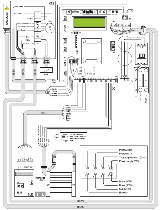
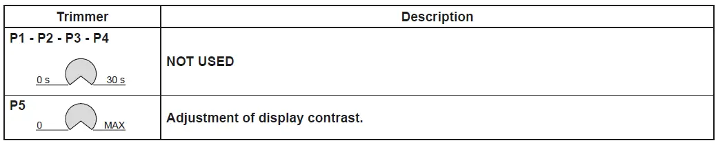
ADJUSTMENTS AND SIGNALS
| Dip-switches | Description | OFF | ON |
| DIP 1 | Future use | – | – |
| DIP 2 | Access to advanced menu | Disabled. | Enabled |
| DIP 3 | Trimmer enabling | Disabled | Enabled |
| DIP 4 | Counter TOT: Number of operations SVC: Number of operations left until service | Disabled | Enabled |
| DIP 5 | Access to service menu | Disabled | Enabled |
| DIP 6 | Door operating data display (F working, I Bus, I peak, V Bus) | Disabled | Enabled |
| DIP 7 | Future use | – | – |
| DIP 8 | Cyclic operation menu | Disabled | Enabled |
| LED | On |
| DL2 | Closing position |
| DL3 | Deceleration |
| DL6 | Partial opening |
| DL7 | Opening position |
| DL15 | Autostart |
| Buttons | Description |
| S2 | USED FOR PROGRAMMING |
| S3 | NOT USED |
| S4 | NOT USED |
| S5 | USED FOR PROGRAMMING |
| FUSES | |||
| ID | Value | Size | Circuit |
| F1 – F2 | 12A – 500V | 10.3 x 38 | Single phase line |
POSITION ADJUSTMENT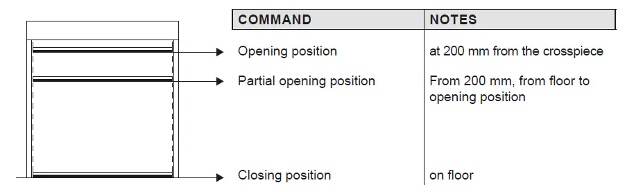
TROUBLESHOOTING
| Display message | Problem | Check |
| Current limit exceeded | Requested motor torque exceeds available torque. | • Reduce opening speed. • Check power supply. • Check power supply wiring. |
| Encoder battery | Absolute encoder battery flat or position read error | • Switch off the control panel, wait 3 minutes and reconnect the power supply. If the problem is not resolved, try again. • If the encoder battery message remains displayed, replace the encoder. |
| Insert brake resistance | Voltage on BUS exceeds threshold | • Switch off the control panel, wait 3 minutes and reconnect the power supply. • If the error reoccurs, check that the voltage on the BUS is lower than 360 V. |
| Max. BUS voltage | BUS voltage exceeds threshold | • Switch off the control panel, wait 3 minutes and reconnect the power supply. • Check the control panel power supply voltage. |
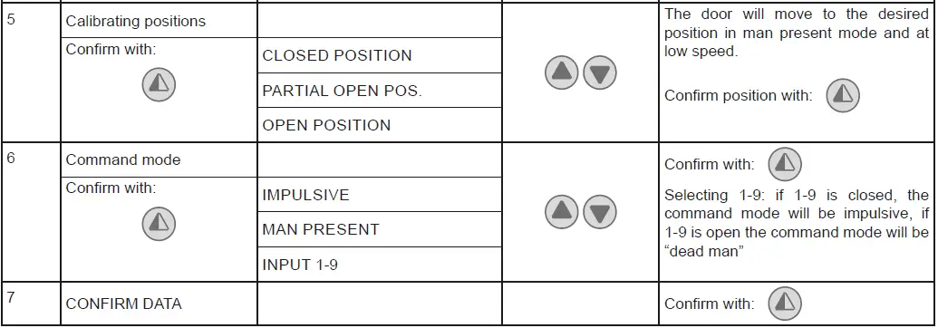
INSTALLATION MENU
When the control panel is switched on, after showing the messages DITEC and microprocessor and card FW VERSION, the device automatically enters the installation menu and displays the message SELECT LANGUAGE
Confirm with
Remove cables from PIN 3, 4, 20 during programming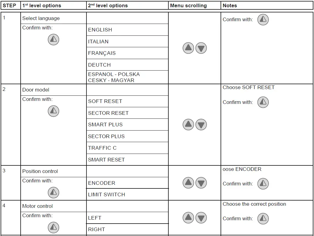
PROGRAMMING COMPLETED
The door is now programmed and operating with the set default speed values.
With the door MOVING, the voltage and current values will be displayed on the BUS.
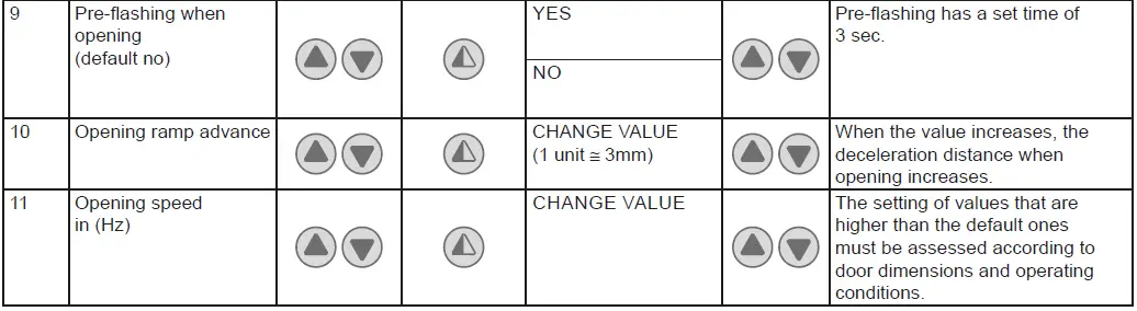
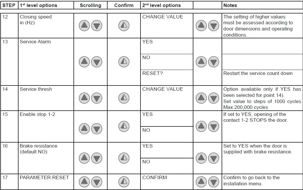
ADVANCED MENU
The advanced menu allows you to modify the position of the limit switches which have previously been set and modify the set default parameters.
To access the Advanced Menu: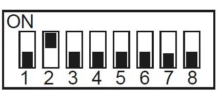
- STOP the door
- Set DIP 2 to ON
“ENCODER CALIB.”, the first item in the advanced menu, will appear on the display.
ONCE PROGRAMMING HAS ENDED, SET DIP2 TO OFF
Remove cables from PIN 3, 4, 20 during programming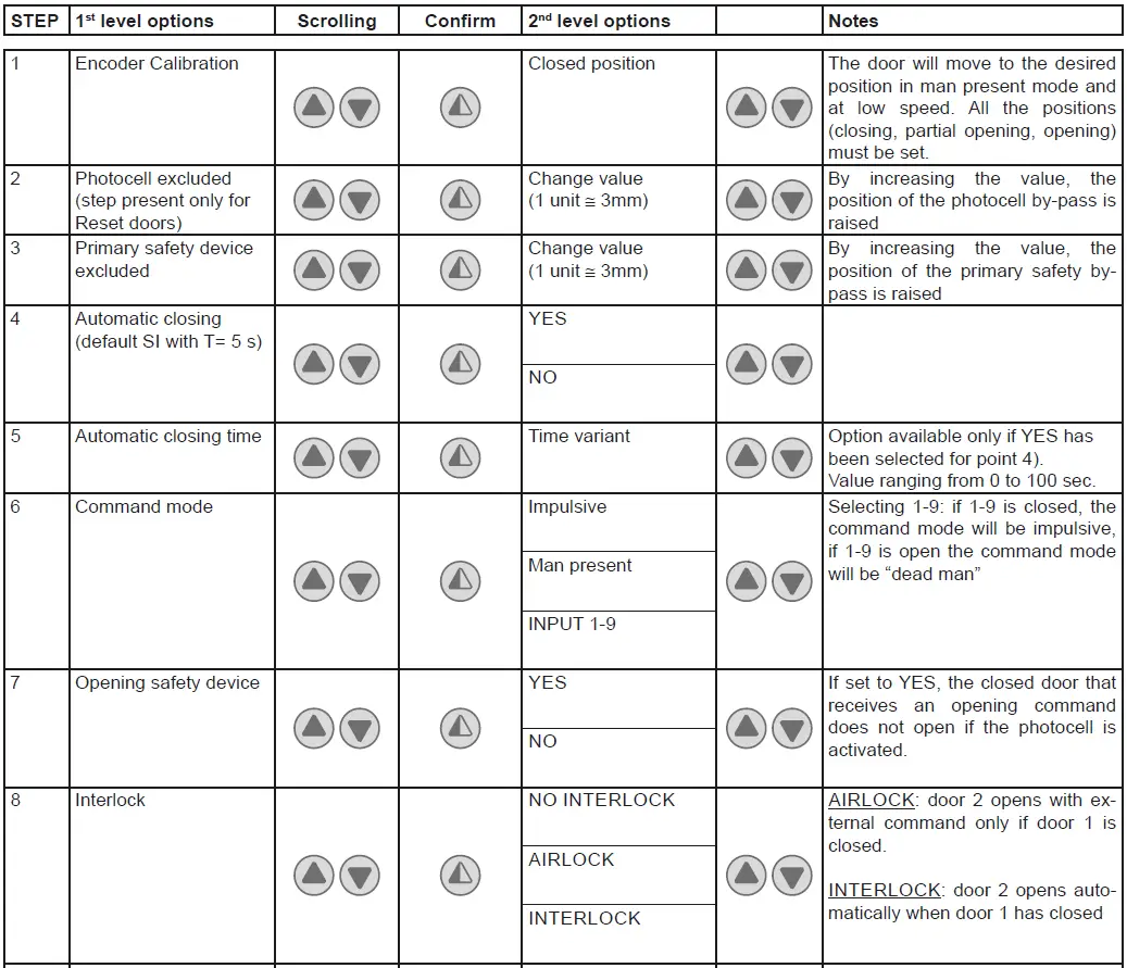
ONCE PROGRAMMING HAS ENDED, SET DIP2 TO OFF
Timed opening menu
With door in STOP position and DIP 8 ON you enter the menu CYCLIC MODE. By activating this mode it is possible to set a timed opening at regular time intervals. Once the mode is set put DIP 8 OFF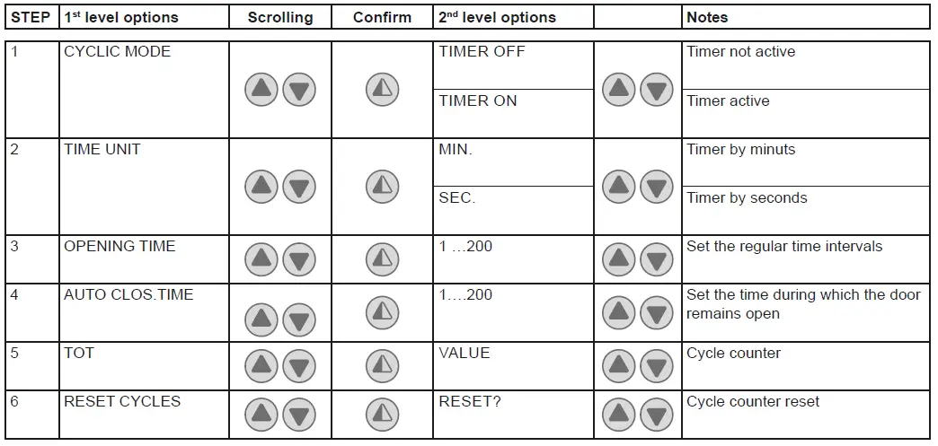
When CYCLIC MODE is active, the display shows every 2 sec: TOT cycle – count down to next open/OPENING TIME
Service menu (password required)
The Service menu is used to modify the brake resistance thresholds, the overcurrent threshold and the anti-wind function when the encoder intervenes.
To access the Service menu:
- STOP the door
- Set DIP5 to ON
- Enter the PW: button sequence OPEN- OPEN- CLOSE- PARTIAL OPENING
Remove cables from PIN 3, 4, 20 during programming
| STEP | 1st level options | Notes |
| 1 | MIN BRAKING VOLT. Default 340Vdc | Threshold for partial intervention of braking resistance |
| 2 | MAX BRAKING VOLT. Default 380Vdc | Threshold for total intervention of braking resistance |
| 3 | OVERCURRENT LIMIT Default 10A | If the current on the BUS exceeds the set threshold, the door opens at half the speed to reduce absorption. |
| 4 | RAMP SLOPE DURING OPENING | Changes the slope of the deceleration ramp when opening. Default 15. (If the value is increased, the ramp distance is reduced). |
| 5 | BATTERY LEVEL | Visualizes the encoder battery charge level from 0% to 100% |
| 6 | ALARM LIST | The last 50 alarms are displayed: Overcurrent; bus voltage exceeds limit, Intervention of brake resistance, inverter overtemperature, faulty motor driver (encoder). To exit, press partial opening |
ONCE PROGRAMMING HAS ENDED, SET DIP5 TO OFF
Display messages
| MESSAGE | SITUATION | NOTES |
| Ditec | door closed waiting for command | |
| Opening of VBUS IBUS | door opening | |
| Door open – automatic closing time | Door open | |
| Closing of VBUS IBUS | door closing | |
| Input 40 closed; input 8 open | intervention of photocell | When door is moving |
| input 40 open; input 8 closed | intervention of encoder (SLE) | When door is moving |
| Thermal or release micro open | Intervention of safety micro on manual opening device / intervention of motor thermal switch. | |
| Opening safety device activated | photocell engaged when door is closed and door does not open | Message that only appears if the “opening safety” function is set to YES on the advanced menu (step 7). |
| Door stopped | stop command activated |
Interlock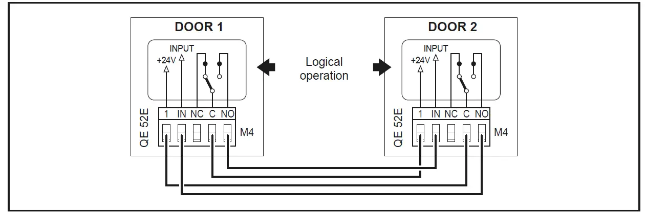
ADJUSTING AND STARTING
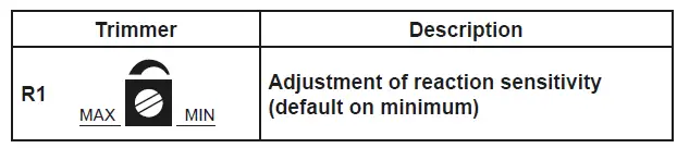
Adjustment of the Safety Linear Encoder (SLE)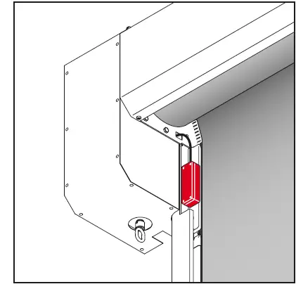
| LED | ON / Flashing | OFF |
| PWR | Power supply on | Power supply off |
| SA | • Initialisation • Intervention due to obstacle • Test running • Test failed / alarm | Normal operating no obstacle. |
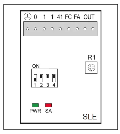
| Dip- switches | Description | OFF | ON |
| DIP 1 | Control panel type | 48E / 52E | / |
|
DIP 2 | Obstacle detected after FC closing limit switch |
Disabled | Enabled (only control panels with INVERTER) |
| DIP 3 | Scale of sensitivity | HIGH (doors close quickly) | LOW (doors close slowly) |
|
DIP 4 | Limit switch polarity | 0 = Limit switch common 48E | 1 = Limit switch common 52E) |
TROUBLESHOOTING
Before performing and operations and working on the electronic equipment make sure that the power supply has been disconnected
The following instructions are for qualified and authorised personnel only. Specific laws and standards must always be complied with even when not expressly indicated.
For repair work or replacements, use only original Ditec spare parts.
| COMMAND | PROBLEM | CHECK |
| Any command with the curtain in any position | The curtain and the motor do not move | • STOP activated (“Stop” LED on push-button panel permanently on) • Motor with thermal switch activated • Manual operation safety micro activated • One of the power devices faulty (control panel, motor, motor connection cable) |
| Opening command with curtain closed | The motor does not move | • Opening command not connected correctly or faulty (commands 1 – 3) • Closing command always activated or short-circuited |
| Closing command with curtain open | The motor does not move | • Closing command not connected correctly or faulty (commands 1 – 4) • Safety device activated (Stop button LED flashing) • Opening command always activated or short-circuited • Failed safety device autotest (Stop LED on push-button panel OFF) |
| Stop activated during an operation | The motor does not stop | • Stop command not working or incorrectly connected (Stop LED on push-button panel does not come on) |
| The motor stops late | • Motor brake worn or faulty | |
| Activation of a safety device during closing | Door movement is not reversed | • Safety device faulty or not connected correctly • Check earth connections. • Check photocell bypass position. |
| Automatic closure activated with curtain open | The door does not close automatically after the time set with TC | • Automatic closure not enabled correctly • Opening command always activated or short-circuited • Failed safety device autotest |
| During an operation | The curtain does not stop correctly at the limit switch | • Check motor brake • Check connection of encoder magnet to the motor shaft |
NB: for diagnostics specifically for the inverter panel 52E, also see page 37
MAINTENANCE TO BE CARRIED OUT EVERY 6 MONTHS
Regular inspections should be made according to national regulations and product documentation by a Ditec trained and qualified technician. The number of service occasions should be in accordance with national requirements and with the product documentation.
Safety Devices
- Check the correct operation of the safety device Linear Encoder (SLE)
- Check the correct operation of the safety photocells Side guides
- Check the guides wearing and the relevant curtain sliding
Installation / Fitting
- Tighten the fitting screws of the uprights with the crosspiece
- Check the anchoring of the door to the door frame
Motor
- Check the fixing of the motor to the relevant support
- Check if encoder is working and its battery level
- Check the brake disc wearing. If necessary replace the disc
- Check motor silent block operation and integrity
Main Shaft
- Check the good bearing supports fixing
- Lubricate the support of the bearings by suitable grease inlet
Zipper status
- Check wearing and cleaning of the zipper
Maintenance Plan
The table below shows the recommended interval – in months – when to replace parts during preventive maintenance.
| Part | Part number | Cycles / hour operation | Abusive Environment (1) | ||
| <10 Low Traffic | <30 Medium Traffic | >30 High Traffic | |||
| Months | Months | Months | |||
| Brake disc | 622337 | 36 | 24 | 12 | 12 |
| 29448ARR | |||||
| Upper guide | 29448ARL | 48 | 36 | 24 | 24 |
| 29448B | |||||
| Lower guide | BGBST | 48 | 36 | 24 | 24 |
| Guide compensation spring | KSPRING | 36 | 24 | 12 | 12 |
| Lens group and spacer for SLE | 6GLSLEC | 36 | 24 | 12 | 12 |
| Motor silent block | 5AV402510 | 48 | 36 | 24 | 24 |
Dirty or dusty environment, operating temperature near to 0°C or over 35°C, wind pressure within 20% of the maximum limit.
REINSERT THE CURTAIN
- Close the upper part of the plastic guides (P) by pushing on the outer side.
- Insert each tooth side edge (Q) of the curtain in the relevant guide, if necessary to make easier the operation remove the higher screw (R).
- Roll down the curtain so the bottom edge is 0.5m beneath the curtain inlet slot
USE INSTRUCTIONS
GENERAL SAFETY PRECAUTIONS
- This user handbook is an integral and essential part of the product and must be delivered to the users.
- Keep this document and pass it on to any future users.
- This automation is a “vertical-roll door”; it must be used for the specific purpose for which it was designed. Any other use is to be considered inappropriate and so dangerous. Assa Abloy Entrance Systems AB declines all responsibility for damage caused by improper, incorrect or unreasonable use.
- The device may be used by children over the age of 8 and by people with reduced physical, sensorial or mental abilities, or lack of experience or knowledge, as long as they are properly supervised or have been instructed in the safe use of the device and the relative hazards.
- Cleaning and maintenance work must not be carried out by children unless they are supervised.
USE PRECAUTIONS
- Do not enter the door action area while the door is moving.
- In the event of a fault or malfunction, turn off the main switch. The operations of maintenance, adjustment, and repair must be carried out by skilled and authorized staff.
- Each automation has its own “Installation and Maintenance handbook”, reporting the periodical maintenance plan. Please take care to check all the safety devices.
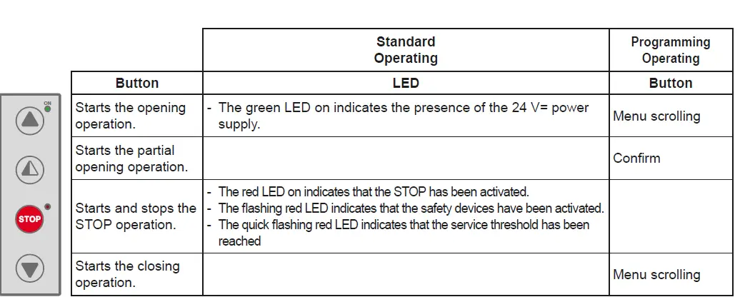
BUTTONS
![]()
- Full opening: the door opens completely. The stroke can be fixed via the end-stop microswitch.
- Partial opening: the door opens partially, to a point time-regulated by the RP trimmer.
- STOP: the door stops immediately.
- Closing: the door closes completely. The stroke can be fixed via the end-stop microswitch
OPTIONAL DS – MANUAL OPERATION
To manually raise the curtain in the event of a power failure or fault, raise the curtain to the “open door” position, as shown
Do not leave the manual operation rod hanging on the ring during normal door operation. Use the special wall-mounted fastening clip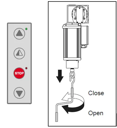
Regular inspections should be made according to national regulations and product documentation by a Ditec trained and qualified technician. The number of service occasions should be in accordance with national requirements and with the product documentation.
Safety Devices
Check the correct operation of the safety device Linear
Encoder (SLE)
Check the correct operation of the safety photocells
Side guides
Check the guides wearing and the relevant curtain sliding
Installation / Fitting
- Tighten the fitting screws of the uprights with the crosspiece
- Check the anchoring of the door to the door frame
Motor
- Check the fixing of the motor to the relevant support
- Check if encoder is working and its battery level
- Check the brake disc wearing. If necessary replace the disc
- Check motor silent block operation and integrity
Main Shaft
- Check the good bearing supports fixing
- Lubricate the support of the bearings by suitable grease inlet
Zipper status
Check wearing and cleaning of the zipper
Maintenance Plan
The table below shows the recommended interval – in months – when to replace parts during preventive maintenance.
| Part | Part number | Cycles / hour operation | Abusive Environment (1) | ||
| <10 Low Traffic | <30 Medium Traffic | >30 High Traffic | |||
| Months | Months | Months | |||
| Brake disc | 622337 | 36 | 24 | 12 | 12 |
| 29448ARR | |||||
| Upper guide | 29448ARL | 48 | 36 | 24 | 24 |
| 29448B | |||||
| Lower guide | BGBST | 48 | 36 | 24 | 24 |
| Guide compensation spring | KSPRING | 36 | 24 | 12 | 12 |
| Lens group and spacer for SLE | 6GLSLEC | 36 | 24 | 12 | 12 |
| Motor silent block | 5AV402510 | 48 | 36 | 24 | 24 |
Dirty or dusty environment, operating temperature near to 0°C or over 35°C, wind pressure within 20% of the maximum limit.
| Date | Cycle counter | Signature |
APPLICATIONS
Use: 4 (minimum 5 years of working life with 300 cycles a day) Applications: INTENSE (for industrial and commercial access with intense use).
- Service class, running times, and the number of consecutive cycles are to be taken as merely indicative having been statistically determined under average operating conditions, and cannot therefore be applied to each individual case. Reference is to the period when the product functions without the need for any extraordinary maintenance.
- Independent variables such as friction, balancing and environmental factors may substantially alter the lifespan or performance characteristics of the automatic access or parts thereof (including the automatic systems). It is the responsibility of the installer to adopt suitable safety measures for each single installation.
SOUND PRESSURE
sound pressure level LPa ≤ 70 dBa
DISMANTLING
For disassembly of the unit. The door is dismantled in the reverse sequence of the installation procedure. The doors should be disposed of in an environmentally responsible manner and according to local stipulations
CLEANING INSTRUCTIONS (DOOR AND COMPONENTS)
High pressure should be avoided on curtain and electrical devices or in case not at close range.
Warm water or other cleaning liquids can be used if ≤ 40°.
About cleaning products:
- all sorts of detergents can be used, preferably of the non-ionic type. A limited amount of alcohol may be present
- avoid the presence of strong oxidizing ingredients as bleaching agents (hypochlorite, peroxides…)
- Strong alkaline cleaners should be avoided, especially for continuous cleaning. The same accounts for very acidic products
- avoid the presence of abrasive material in the cleaning liquid
- The use of strong polar solvents as MEK, acetone, ethers, dimethyl formaldehyde, cyclohexanone etc is strongly forbidden
- The use of hydrocarbons should be avoided. It might be used for occasional cleaning or degreasing
DECLARATION OF CONFORMITY
We: Assa Abloy Entrance Systems AB Lodjursgatan 10 SE-261 44 Landskrona Sweden declare under our sole responsibility that the type of equipment with name / description: SOFT RESET FOOD
Roll-up high speed door With performance levels as declared in the accompanying Declaration of Performance and the product label, and electrical drive unit as identified in the log book provided with it, is in compliance with the following directives:
- 2006/42/EC Machinery Directive (MD)
- 2014/30/EU Electromagnetic Compatibility Directive (EMCD)
- 2011/65/EU On the restriction of the use of certain hazardous substances in electrical and electronic equipment (RoSH)
Harmonized European standards which have been applied:
- EN 13241-1 EN 61000-6-2 EN 61000-6-3
- EN 60335-1 EN 60204-1
Other standards or technical specifications, which have been applied:
- EN 60335-2-103
EC type examination or certificate issued by a notified or competent body (for full address, please contact
Assa Abloy Entrance Systems AB) concerning the equipment:
CSI Spa Reg. – N° 0497
The manufacturing process ensures the compliance of the equipment with the technical file.
The manufacturing process is regularly accessed by 3rd party.
Ditec C/O Dynaco Europe n.v. Waverstraat 21 B-9310 MOORSEL TVA/BTW: BE 439,752,567 RCA/HRA 64232 © ASSA ABLOY


