![]() FR070 Light Unit Turn Signal (Pair)
FR070 Light Unit Turn Signal (Pair)
User Manual
Rev.: 00
FR070 Light Unit Turn Signal (Pair)
Welcome to Rizoma
Before you start
We are pleased to welcome you into the world of RIZOMA, and we congratulate you for your excellent choice. Please carefully follow the instructions in this guide, which will allow you to mount and use the product correctly and enjoy all the features it has.
For your protection and safety, RIZOMA expressly recommends that you have the installation of the product performed by skilled personnel. Improper installation, repair or maintenance, can cause accidents. Keep this user guide as a reference for the future.
General conditions
Attention: This component comes assembled for shipping purposes only. Tighten all fasteners to appropriate torque specifications before riding.
Descriptions preceded by this symbol contain information, instructions, or procedures, which, if not followed, may result in death or serious injury.
- Carefully read, understand and follow these instructions, they are an essential part of the product. If you have any doubt whatsoever regarding the installation or use of your RIZOMA product, please see your authorized RIZOMA dealer for assistance (on www.rizoma.com).
- For correct installation, all tightening has to be done after the correct positioning of the accessories without restricting the moving parts, to not compromise the correct functioning of the product.
- After installing any Rizoma product, please check that all related components of the motorbike function e.g. brakes, throttle, clutch, lights and steering. We strongly suggest to repeat these checks periodically, especially after long trips or prolonged periods of not using the bike.
Your RIZOMA products require regular inspection and maintenance. The more you ride the more often you must inspect your RIZOMA products. If your products are leaking, bent, deformed, cracked, chipped or worn, no matter how slight, immediately have a RIZOMA dealer inspect the products before you ride again.
In any case never try to repair or modify the Rizoma products or their components, always replace with Rizoma original components.
Rizoma products may not be compatible with your motorcycle or with other aftermarket equipment installed before. or your safety Rizoma suggests to always contact your RIZOMA dealer.
O.E.M.: original equipment manufacturer.
Turn signal “LIGHT UNIT”
Before installing the RIZOMA indicator,please refer to the motorcycle operation and maintenance manual to check the power of the (original) OEM indicators, expressed in Watts.lf they are LED or 6/10/21W bulb versions, follow the instructions for connection very carefully.Any connection must take place using the relevant connectors. Caution: never cut the wires, as this could lead to malfunctions.
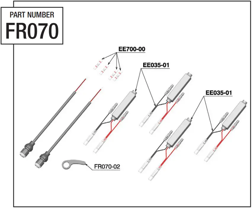
![]() Before you start mounting the product please check the completeness of the kit on the part list. The difficulty level and the time of assemblage shown do not include the removal of OEM components. The warrantee is not valid for any electric wires cutting or any product modify or tampering. In the kit are included n°02 resistor of 15Ω 10W. Consult the website www.rizoma.com, in the turn signals “LIGHT UNIT” section click “MEDIA” to download the PDF document homologation.
Before you start mounting the product please check the completeness of the kit on the part list. The difficulty level and the time of assemblage shown do not include the removal of OEM components. The warrantee is not valid for any electric wires cutting or any product modify or tampering. In the kit are included n°02 resistor of 15Ω 10W. Consult the website www.rizoma.com, in the turn signals “LIGHT UNIT” section click “MEDIA” to download the PDF document homologation.
Warning: Make sure that your motorbike is standing firmly before you start work, as a fall may lead to damage to the motorbike or injury to you or others.
WARNING: TO CLEAN YOUR PRODUCT DON’T USE DETERGENT, AGGRESSIVE PRODUCTS OR ABRASIVE SPONGE THAT CAN DAMAGE OR SCRATCH YOUR PRODUCT, BUT USE ONLY NEUTRAL DETERGENT WITH COLD WATER.![]() Turn signals do not comply with applicable DOT or other Federal Regulations. For off-road use only. Use on-road could cause another motorist or pedestrian not to see you, resulting in an accident, personal injury or death. Improper installation could damage the electrical system of the motorcycle and cause a fire, resulting in personal injury or death. Electrical shock hazard. Disconnect the battery before starting to install turn signals.
Turn signals do not comply with applicable DOT or other Federal Regulations. For off-road use only. Use on-road could cause another motorist or pedestrian not to see you, resulting in an accident, personal injury or death. Improper installation could damage the electrical system of the motorcycle and cause a fire, resulting in personal injury or death. Electrical shock hazard. Disconnect the battery before starting to install turn signals.
|
INSTALLATION
Step 1![]() Your garantee will not apply if the indicator has not been correctly installed and connected to the electrical supply on your motorbike. Do not carry out the installation unless you are specifically trained to do so; otherwise, please contact an authorized dealer Rizoma. Your garantee does not apply to damage due to wrong connection or excess voltage. Improper mechanical installation or orientation of the indicator may invalidate your motorbike’s roadworthiness and insurance protection, or even lead to accidents. Check that your indicator are securely fitted before you ride your motorbike. Your indicator may heat up during use. Contact with bare skin or heat-sensitive objects may lead to damage or injury. Make sure that your motorbike is standing firmly before you start work, as a fall may lead to damage to the motorbike or injury to you or others. Use the washer and the M6 nut to install your indicator. Install the cover rubber on nut insert the wires and the sheath, use household detergent or grease to help. Make sure that your indicator are fitted in such a way as to cast a beam horizontal to direction of travel. Orientation is important to safety traffic and essential to your bike’s roadworthiness. Refer to the directive in force for more details on fitting.
Your garantee will not apply if the indicator has not been correctly installed and connected to the electrical supply on your motorbike. Do not carry out the installation unless you are specifically trained to do so; otherwise, please contact an authorized dealer Rizoma. Your garantee does not apply to damage due to wrong connection or excess voltage. Improper mechanical installation or orientation of the indicator may invalidate your motorbike’s roadworthiness and insurance protection, or even lead to accidents. Check that your indicator are securely fitted before you ride your motorbike. Your indicator may heat up during use. Contact with bare skin or heat-sensitive objects may lead to damage or injury. Make sure that your motorbike is standing firmly before you start work, as a fall may lead to damage to the motorbike or injury to you or others. Use the washer and the M6 nut to install your indicator. Install the cover rubber on nut insert the wires and the sheath, use household detergent or grease to help. Make sure that your indicator are fitted in such a way as to cast a beam horizontal to direction of travel. Orientation is important to safety traffic and essential to your bike’s roadworthiness. Refer to the directive in force for more details on fitting.
ELECTRIC CONNECTIONS
Step 2![]() Disconnect the battery before starting to install turn signals. To avoid damage to the electrical system of the bike, for electrical connection of turn signal we recommend to use the Rizoma electric wiring. Consult the Rizoma catalog or the web site www.Rizoma.com to choose the correct electric wiring. Arrange the wires to protect them from splash water and fasten them as appropriate, such as with wire connectors. Reconnect the motorbike battery and test the turn signal. Align the turn signal as described above. If your turn signal should flash at a rate faster (some original relays only work properly at the original turn signal) we recommend using a power-independent relays from Rizoma (consult the Rizoma catalog or the web site www.Rizoma.com). It should, in fact, this solution preferred for its simplicity, safety, reliability and speed of install. Otherwise, we recommend using the Rizoma resistor, consult the authorized dealer or the web site www.rizoma.com for the purchase of the correct resistor. Install the resistors in such a way that the power value (W) equal at the power value of original turn signal (see SCHEMA). Install the resistors in such a way that heat can escape effectively. These measures may disable the rapid flashing function to alert the rider that one of the turn signal is no longer working. Check your turn signal before each motorcycle trip. These resistors will heat up if the turn signal is used for an extended period. Make sure that other components or person are safe.
Disconnect the battery before starting to install turn signals. To avoid damage to the electrical system of the bike, for electrical connection of turn signal we recommend to use the Rizoma electric wiring. Consult the Rizoma catalog or the web site www.Rizoma.com to choose the correct electric wiring. Arrange the wires to protect them from splash water and fasten them as appropriate, such as with wire connectors. Reconnect the motorbike battery and test the turn signal. Align the turn signal as described above. If your turn signal should flash at a rate faster (some original relays only work properly at the original turn signal) we recommend using a power-independent relays from Rizoma (consult the Rizoma catalog or the web site www.Rizoma.com). It should, in fact, this solution preferred for its simplicity, safety, reliability and speed of install. Otherwise, we recommend using the Rizoma resistor, consult the authorized dealer or the web site www.rizoma.com for the purchase of the correct resistor. Install the resistors in such a way that the power value (W) equal at the power value of original turn signal (see SCHEMA). Install the resistors in such a way that heat can escape effectively. These measures may disable the rapid flashing function to alert the rider that one of the turn signal is no longer working. Check your turn signal before each motorcycle trip. These resistors will heat up if the turn signal is used for an extended period. Make sure that other components or person are safe.
MOUNTING SOLUTION TURN SIGNAL
INSTALL RUBBER
![]()
CONNECTIONS
![]()
SCHEMA 1
![]()
Assembly diagram for motorcycles with electrical system featuring LED indicators.
SCHEMA 2
![]()
Assembly diagram for motorcycles with electrical system featuring (from 6W to < 10W) bulb indicators.
SCHEMA 3
![]()
Assembly diagram for motorcycles with electrical system featuring (21W) bulb indicators.
SCHEMA 4
![]()
Assembly diagram for motorcycles with electrical system featuring (10W) bulb indicators.
ELECTRIC CONNECTIONS
Step 10
| MODEL | YEAR | FRONT | REAR |
| BMW R1200GS | 10-13 | SCHEMA 1 | SCHEMA 1 |
| BMW S1000RR | 10-14 | SCHEMA 2 | SCHEMA 2 |
| BMW F800R | 09-11 | SCHEMA 3 | SCHEMA 3 |
| BMW K1300R | 09-11 | SCHEMA 3 | SCHEMA 3 |
| BMW C600 SPORT | 12-15 | OEM | SCHEMA 2 |
| BMW F800GS | 13-15 | SCHEMA 2 | SCHEMA 2 |
| BMW R1200GS | 13-16 | SCHEMA 2 | SCHEMA 2 |
| BMW S1000R | 14-16 | SCHEMA 1 | SCHEMA 2 |
| BMW S1000RR | 15-16 | SCHEMA 1 | SCHEMA 1 |
| BMW R NINE T (ORIGINAL LED FR) | 14-16 | SCHEMA 1 | SCHEMA 1 |
| BMW R NINE T (ORIGINAL BULB FR) | 14-16 | SCHEMA 4 | SCHEMA 4 |
| BMW R1200R (ORIGINAL LED FR) | 15-16 | SCHEMA 1 | SCHEMA 1 |
| BMW R1200RS (ORIGINAL LED FR) | 15-16 | SCHEMA 1 | SCHEMA 1 |
| BMW S1000XR (ORIGINAL LED FR) | 15-16 | SCHEMA 1 | SCHEMA 1 |
| BMW R NINE T 1200 SCRAMBLER | 16 | SCHEMA 1 | SCHEMA 1 |
![]() In motorcycles equipped with a control indicator (some BMW models), it may be necessary to install other resistors activated parallel to the current circuit of the indicators in order to avoid unnecessary ignition of the control indicator. For some BMW models, purchase the EE149H kit.
In motorcycles equipped with a control indicator (some BMW models), it may be necessary to install other resistors activated parallel to the current circuit of the indicators in order to avoid unnecessary ignition of the control indicator. For some BMW models, purchase the EE149H kit.
Step 11
| APRILIA RSV4/RSV4 R/RSV4 FACTORY | 09-12 | OEM | SCHEMA 4 |
| APRILIA TUONO 1100 V4 RR | 19-20 | SCHEMA 1 | SCHEMA 1 |
| APRILIA RS660 | 20> | OEM | SCHEMA 1 |
| APRILIA RSV4 1100 | 21> | OEM | SCHEMA 1 |
| APRILIA RSV4 1100 USA VERSION | 21> | SCHEMA 1 | SCHEMA 1 |
| BMWG 310 R | 16> | SCHEMA 1 | SCHEMA 1 |
| BMW G 310 GS | 17> | SCHEMA 1 | SCHEMA 1 |
| BMW F850 GS | 18> | SCHEMA 1 | SCHEMA 1 |
| BMW R1250 GS/ADVENTURE/HP | 19-20 | SCHEMA 1 | SCHEMA 1 |
| BMW F 900 XR | 20> | SCHEMA 1 | SCHEMA 1 |
| BMW F 900 R | 20> | SCHEMA 1 | SCHEMA 1 |
| BUELL XB12 | 09> | SCHEMA 3 | SCHEMA 3 |
| DUCATI MONSTER 937 | 21> | OEM | SCHEMA 1 |
| DUCATI PANIGALE V2 955 | 20> | SCHEMA 1 | SCHEMA 1 |
| DUCATI STREETFIGHTER V4 1100 | 20> | SCHEMA 1 | SCHEMA 1 |
| DUCATI STREETFIGHTER V4 S 1100 | 20> | SCHEMA 1 | SCHEMA 1 |
| DUCATI SCRAMBLER 1100 PRO | 20> | SCHEMA 1 | SCHEMA 1 |
| DUCATI SCRAMBLER 1100 SPORT PRO | 20> | SCHEMA 1 | SCHEMA 1 |
| DUCATI MONSTER 821/1200 | 14-17 | SCHEMA 2 | SCHEMA 2 |
| DUCATI SCRAMBLER | 15> | SCHEMA 1 | SCHEMA 1 |
| DUCATI HYPERMOTARD 796/1100 | 08-12 | SCHEMA 2 | SCHEMA 3 |
| DUCATI MULTISTRADA 1200 | 10> | OEM | SCHEMA 2 |
| DUCATI S2R | 07> | SCHEMA 3 | SCHEMA 3 |
Step 12
| DUCATI 748 | 00-03 | SCHEMA 2 | SCHEMA 2 |
| DUCATI HYPERMOTARD 1100S | 09> | OEM | SCHEMA 4 |
| DUCATI MULTISTRADA 1260/1260 S | 18-20 | SCHEMA 1 | SCHEMA 1 |
| DUCATI HYPERMOTARD 950/SP | 19> | SCHEMA 1 | SCHEMA 1 |
| DUCATI MONSTER 1200S | 17> | SCHEMA 1 | SCHEMA 1 |
| DUCATI MONSTER 821 | 18-20 | SCHEMA 1 | SCHEMA 1 |
| DUCATI MONSTER 797 | 17-18 | SCHEMA 1 | SCHEMA 1 |
| DUCATI SUPERSPORT 939/939 S | 17-20 | SCHEMA 1 | SCHEMA 1 |
| DUCATI MULTISTRADA 1200 ENDURO | 16-18 | OEM | SCHEMA 1 |
| DUCATI STREETFIGHTER 848 | 11-15 | SCHEMA 1 | SCHEMA 4 |
| DUCATI DIAVEL 1260/1260S | 19-20 | OEM | SCHEMA 1 |
| DUCATI 848 | 07-13 | SCHEMA 3 | SCHEMA 3 |
| DUCATI SCRAMBLER 400 | 16-21 | SCHEMA 1 | SCHEMA 1 |
| DUCATI XDIAVEL 1262/1262 S | 16-20 | SCHEMA 1 | SCHEMA 1 |
| DUCATI PANIGALE 1299 | 15-17 | SCHEMA 1 | SCHEMA 1 |
| DUCATI MONSTER 1200 | 17> | SCHEMA 1 | SCHEMA 1 |
| DUCATI STREETFIGHTER / S | 09-14 | SCHEMA 3 | SCHEMA 3 |
| DUCATI MONSTER 696 | 09-14 | SCHEMA 3 | SCHEMA 3 |
| DUCATI MONSTER 796 | 10-14 | SCHEMA 1 | SCHEMA 2 |
| DUCATI 959 PANIGALE | 16-19 | SCHEMA 1 | SCHEMA 1 |
| DUCATI PANIGALE 1199/899 | 12-15 | SCHEMA 1 | SCHEMA 4 |
| DUCATI SCRAMBLER 800 ICON | 15-20 | SCHEMA 1 | SCHEMA 1 |
| DUCATI HYPERMOTARD | 13> | SCHEMA 1 | SCHEMA 4 |
Step 13
| DUCATI SCRAMBLER 800 ICON | 21> | SCHEMA 1 | SCHEMA 1 |
| DUCATI SCRAMBLER 800 DESERT SLED | 17-20 | SCHEMA 1 | SCHEMA 1 |
| DUCATI MULTISTRADA 950/9505 | 19> | OEM | SCHEMA 1 |
| DUCATI SCRAMBLER 800 CAFE RACER | 17> | SCHEMA 1 | SCHEMA 1 |
| DUCATI SCRAMBLER 800 FULL THROTTLE | 15> | SCHEMA 1 | SCHEMA 1 |
| DUCATI SUPERSPORT 950/950S | 21> | SCHEMA 1 | SCHEMA 1 |
| DUCATI PANIGALE V4 1100 | 18> | SCHEMA 1 | SCHEMA 1 |
| DUCATI PANIGALE V4 S 1100 | 18> | SCHEMA 1 | SCHEMA 1 |
| HONDA CB 1000R | 08-17 | SCHEMA 3 | SCHEMA 3 |
| HONDA HORNET 600 | 07-10 | SCHEMA 3 | SCHEMA 3 |
| HONDA AFRICA TWIN CRF 1000 L | 18-20 | SCHEMA 2 | SCHEMA 2 |
| HONDA CBR 1000RR | 09-19 | OEM | SCHEMA 3 |
| HONDA MSX125 | 13-17 | SCHEMA 3 | SCHEMA 3 |
| HONDA INTEGRA | 11-13 | OEM | SCHEMA 3 |
| HONDA HORNET 600 | 11> | SCHEMA 2 | SCHEMA 3 |
| HONDA CBR 600RR | 07-16 | SCHEMA 3 | SCHEMA 3 |
| HONDA CB650F | 1417 | SCHEMA 3 | SCHEMA 3 |
| HONDA CB600 HORNET | 13> | OEM | SCHEMA 3 |
| HUSQVARNA SVARTPILEN 401 | 18> | SCHEMA 1 | SCHEMA 1 |
| INDIAN FTR 1200/1200S | 19> | SCHEMA 4 | SCHEMA 4 |
| KAWASAKI NINJA 1000 ZX-10R SE | 18-20 | SCHEMA 4 | SCHEMA 4 |
| KAWASAIKI NINJA 1000 ZX-10R KRT REPLICA | 19-20 | SCHEMA 4 | SCHEMA 4 |
| KAWASAKI VERSYS-X 300 | 17-20 | SCHEMA 4 | SCHEMA 4 |
Step 14
| KAWASAKI NINJA 650 | 17-19 | OEM | SCHEMA 4 |
| KAWASAKI Z1000 SX | 19> | OEM | SCHEMA 4 |
| KAWASAKI ZX-6R | 19> | OEM | SCHEMA 4 |
| KAWASAKI Z750 | 07-14 | SCHEMA 3 | SCHEMA 3 |
| KAWASAKI Z1000 | 07>09 | OEM | SCHEMA 2 |
| KAWASAKI NINJA 1000 ZX-10R | 17> | SCHEMA 4 | SCHEMA 4 |
| KAWASAKI Z900 | 17-19 | SCHEMA 4 | SCHEMA 4 |
| KAWASAKI Z650 | 17> | SCHEMA 4 | SCHEMA 4 |
| KAWASAKI VERSYS 1000 | 12-14 | SCHEMA 2 | SCHEMA 2 |
| KAWASAKI ZX-6R 636 | 13> | SCHEMA 2 | SCHEMA 4 |
| KAWASAKI Z300 | 15> | SCHEMA 4 | SCHEMA 4 |
| KAWASAKI NINJA300 | 13-15 | OEM | SCHEMA 4 |
| KAWASAKI ER6N | 09-11 | SCHEMA 3 | SCHEMA 3 |
| KAWASAKI ER6N | 12-15 | SCHEMA 1 | SCHEMA 4 |
| KAWASAKI VERSYS 1000 | 17-18 | SCHEMA 4 | SCHEMA 4 |
| KAWASAKI 21000 | 17> | SCHEMA 2 | SCHEMA 2 |
| KAWASAKI ZX-6R | 09-15 | OEM | SCHEMA 2 |
| KAWASAKI NINJA 1000 ZX-10R | 11-15 | SCHEMA 2 | OEM |
| KAWASAKI Z1000 | 10-13 | OEM | SCHEMA 3 |
| KAWASAKI Z1000 | 14-16 | SCHEMA 2 | SCHEMA 2 |
| KAWASAKI 2600 | 12-16 | SCHEMA 2 | SCHEMA 2 |
| KTM 1090 ADVENTURE S-L | 17-19 | SCHEMA 4 | SCHEMA 4 |
| KTM 1190 RC8 | 08-16 | OEM | SCHEMA 3 |
Step 16
| TRIUMPH STREET TRIPLE Ft/RS | 17> | SCHEMA 1 | SCHEMA 1 |
| TRIUMPH SPEED TRIPLE RS | 18> | SCHEMA 1 | SCHEMA 1 |
| TRIUMPH THRUXTON 1200R | 16> | SCHEMA 4 | SCHEMA 4 |
| TRIUMPH BONNEVILLE T120 | 16-20 | SCHEMA 4 | SCHEMA 4 |
| TRIUMPH SPEED TRIPLE 1050 | 08-11 | SCHEMA 3 | SCHEMA 3 |
| TRIUMPH STREET TRIPLE | 08-12 | SCHEMA 3 | SCHEMA 3 |
| TRIUMPH DAYTONA 675 | 09-11 | SCHEMA 3 | SCHEMA 3 |
| TRIUMPH EXPLORER 1215 | 12-14 | SCHEMA 2 | SCHEMA 2 |
| TRIUMPH SPEED TWIN 1200 | 19> | SCHEMA 1 | SCHEMA 1 |
| TRIUMPH STREET TRIPLE R | 12-15 | SCHEMA 1 | SCHEMA 1 |
| TRIUMPH STREET TRIPLE | 13 | SCHEMA 4 | SCHEMA 4 |
| TRIUMPH TIGER 800 | 11> | SCHEMA 2 | SCHEMA 2 |
| TRIUMPH BONNEVILLE T100 | 08-15 | SCHEMA 4 | SCHEMA 4 |
| TRIUMPH SPEED TRIPLE 1200 RS | 21> | SCHEMA 1 | SCHEMA 1 |
| TRIUMPH TRIDENT 660 | 21> | SCHEMA 1 | SCHEMA 1 |
| TRIUMPH SCRAMBLER 1200 XC | 19-20 | SCHEMA 1 | SCHEMA 1 |
| TRIUMPH STREET TRIPLE RX | 16-17 | SCHEMA 4 | SCHEMA 4 |
| YAMAHA YZF-R1 | 20> | SCHEMA 1 | SCHEMA 1 |
| YAMAHA T-MAX 560 | 20> | OEM | SCHEMA 1 |
| YAMAHA T-MAX DX-SX-530 | 17> | OEM | SCHEMA 1 |
| YAMAHA XJR1300 | 15> | SCHEMA 4 | SCHEMA 4 |
| YAMAHA XV950R | 14> | SCHEMA 4 | SCHEMA 3 |
| YAMAHA MT-07 | 13-15 | SCHEMA 4 | SCHEMA 1 |
Step 17
| YAMAHA R1 | 15-16 | SCHEMA 1 | SCHEMA 1 |
| YAMAHA FZ8 | 10> | SCHEMA 2 | SCHEMA 3 |
| YAMAHA XJ6 | 09> | SCHEMA 2 | SCHEMA 2 |
| YAMAHA YZF R1 | 09-14 | SCHEMA 2 | SCHEMA 2 |
| YAMAHA F26 | 06> | SCHEMA 3 | SCHEMA 3 |
| YAMAHA FZ1 | 06> | SCHEMA 3 | SCHEMA 3 |
| YAMAHA YZF R6 | 08-16 | SCHEMA 3 | SCHEMA 3 |
| YAMAHA MT-09/MT-09 TRACER | 13-16 | SCHEMA 4 | SCHEMA 4 |
| YAMAHA XRS700 | 16-17 | SCHEMA 4 | SCHEMA 1 |
| YAMAHA XSR900 | 16-17 | SCHEMA 4 | SCHEMA 4 |
| YAMAHA MT-10 / MT-10 SP | 17-20 | SCHEMA 1 | SCHEMA 1 |
| YAMAHA MT-09 | 17-20 | SCHEMA 4 | SCHEMA 4 |
| YAMAHA R6 | 17> | SCHEMA 1 | SCHEMA 1 |
| YAMAHA MT-07 | 18-20 | SCHEMA 4 | SCHEMA 4 |
| AMAHA TRACER 900/9000T | 18> | SCHEMA 4 | SCHEMA 4 |
| YAMAHA MT-09 | 21> | SCHEMA 1 | SCHEMA 1 |
| YAMAHA MT-09 SP | 21> | SCHEMA 1 | SCHEMA 1 |
| YAMAHA MT-07 | 21> | SCHEMA 1 | SCHEMA 1 |
| YAMAHA TENERE 700 | 19> | SCHEMA 4 | SCHEMA 4 |
| YAMAHA TENERE 700 RALLY EDITION | 20> | SCHEMA 4 | SCHEMA 4 |
| YAMAHA TRACER 700 | 20> | SCHEMA 1 | SCHEMA 1 |
| YAMAHA MT-03 | 20> | SCHEMA 1 | SCHEMA 1 |
| HARLEY DAVIDSON SPORTSTER | 08-12 | SCHEMA 3 | SCHEMA 3 |
Step 18
| HARLEY DAVIDSON FXDR 114 | 19> | SCHEMA 4 | SCHEMA 4 |
| HARLEY DAVIDSON FXDL DYNA | 17> | SCHEMA 1 | SCHEMA 1 |
| HARLEY DAVIDSON SOFTAIL SUM | 18> | SCHEMA 1 | SCHEMA 1 |
| HARLEY DAVIDSON STREET BOB | 18> | SCHEMA 1 | SCHEMA 1 |
| HARLEY DAVIDSON UVEWIRE | 19> | SCHEMA 1 | SCHEMA 1 |
| HARLEY DAVIDSON BREAKOUT | 18> | SCHEMA 1 | SCHEMA 1 |
| HARLEY DAVIDSON FAT BOB | 18> | SCHEMA 1 | SCHEMA 1 |
| HARLEY DAVIDSON FAT BOY | 18> | SCHEMA 1 | SCHEMA 1 |
| HARLEY DAVIDSON LOW RIDER | 18> | SCHEMA 1 | SCHEMA 1 |
| HARLEY DAVIDSON SOFTAIL SUM | 15-17 | SCHEMA 1 | SCHEMA 1 |
| HARLEY DAVIDSON 1200 ORTY-EIGHT | 18> | SCHEMA 3 | SCHEMA 4 |
| HARLEY DAVIDSON VRSC | 08-11 | SCHEMA 3 | SCHEMA 3 |
UPDATE AUGUST 2021
EXCEPTIONS
Step 19![]() WARNING: only for these models do not have to be used the resistors included in the indicators but the kits in the table must be purchased.
WARNING: only for these models do not have to be used the resistors included in the indicators but the kits in the table must be purchased.
| MODEL | YEAR | FRONT | REAR |
| BMW R 18 | 20> | EE188 | EE177 |
| BMW M 1000 RR | 20> | EE078 | EE177 |
| 3MW R 1250 GS | 21> | EE078 | EE177 |
| BMW R NINE T 1200 | 17> | EE149 | EE149 |
| BMW R NINE T 1200 RACER | 17> | EE149 | EE149 |
| BMW R NINE T URBAN GS 1200 | 17> | EE149 | EE149 |
| BMW R NINE T 1200 PURE | 17> | EE149 | EE149 |
| BMW R NINE T 1200 SCRAMBLER | 17> | EE149 | EE149 |
| BMW S 1000 RR | 19> | EE149 | EE149 |
| BMW S 1000 R | 21 > | EE078 | EE177 |
| HONDA CBR 1000 RR | 17-19 | EE158 | EE146 |
| HONDA CBR 1000 RR-R/ SP | 20> | EE158 | EE183 |
| HONDA CB65OR Neo Sport Cafe | 19> | EE167 | EE146 |
| HONDA CB1000R Neo Sport Cafe | 18> | EE167 | EE162 |
| HONDA X-ADV 750 | 17-20 | EE146 | EE154 |
| HONDA X-ADV 750 | 21> | EE191 | EE191 |
| HONDA FORZA 750 | 21> | OEM | EE191 |
| HUSQVARNA VITPILEN 701 | 18> | EE164 | EE164 |
| KTM 1290 SUPER DUKE R | 20> | EE164 | EE164 |
| KTM 790 DUKE | 18> | EE164 | EE164 |
| KTM 890 DUKE | 21> | EE164 | EE164 |
| KAWASAKI Z900RS/Z900RS CAFE’ | 18> | EE155 | EE155 |
| KAWASAKI 71000 (For led indicators equipped models) | 17> | EE155 | EE155 |
| KAWASAKI Z900 | 20> | EE155 | EE155 |
| SUZUKI GSX R 1000 / R | 19> | EE168 | EE168 |
| SUZUKI KATANA 1000 | 19> | EE168 | EE168 |
| SUZUKI GSX-S 1000 | 21> | EE168 | EE168 |
Warnings
RIZOMA reserves the right, in its sole discretion, to make changes to the product and this information at any time and without prior notice. Although many catalogs and advertisements depict riders engaged in extreme or stunt riding, this activity is extremely dangerous, increases the risk of an accident, and increases the severity of any injury.
The action depicted is performed by professionals under strictly controlled riding conditions.
Only you know the limits of your riding ability and only you can control the conditions under which you ride. By and in consideration for his/her purchase and use of the RIZOMA product, the user expressly recognizes and agrees that in the event of any claim arising out of the use of this RIZOMA product, whether such claim is based in contract, warranty, tort (personal injury or wrongful death) or otherwise, the laws of the Republic of Italy shall apply and jurisdiction and venue for any such action shall be in the Courts of Busto Arsizio, Italy.
All riders are strongly urged to take a motorcycle rider safety clinic. Always wear a properly fitted and fastened motorcycle helmet (RIZOMA recommends a full face helmet), that has been approved by ANSI , SNELL, CE, or any other relevant authority, and any other safety equipment necessary for your riding style, such as full finger gloves, boots, and body armor.
Be sure to read and follow all the instructions and warnings that originally accompanied your motorcycle, as well as the literature that accompanied any other component parts installed on your motorcycle.
Be sure that your tires are inflated to the correct pressure and that there is no damage whatsoever in the tread or sidewall of the tire.
Some of our products may not be approved for road circulation in the countries where homologation is required.
Legal note
Thus RIZOMA® srl declines any responsibility for a different use of its products.
Rev.: 00


