Godox VL150II LED Video Light
Warning
- Do not look directly at the light source.
- The luminaire is intended for professional use only.
- Keep out of reach of children.
- Please take off the lamp cover before using.
- Do not leave or store the product if the ambient temperature reads over 40°C.
- Do not fire directly against human eyes as it may cause visual impairment.
- Please use the original power cable, damages caused by using other cables will invalid the warranty.
- As this product do not have a waterproof function, please take measures of waterproof in rainy or damp environment.
- Always keep this product dry. Do not use in rain or in damp conditions.
- Do not use the product in the presence of flammable gases, chemicals and other similar materials.
- The light source contained in this luminaire shall only be replaced by the manufacturer or his service agent or a similar qualified person.
- Do not disassemble. Should repairs become necessary, this product must be sent to an authorized maintenance center.
- The lamp shall be changed if it has become damaged or thermally deformed.
Structure of Product
VL 15011 Light Body
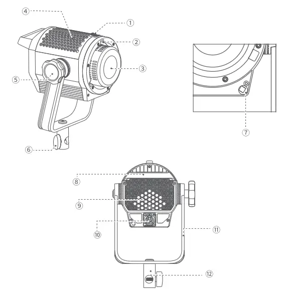
- Accessory Locking Ring
- Bowens Mount
- LED Beads
- Thermovent
- Bracket Locking Ring
- Bracket Sleeve Ring
- Umbrella Input
- Handle
- Thermovent
- Power Input Socket
- U-type Bracket
- Bracket Sleeve
Vll 50I I Controller
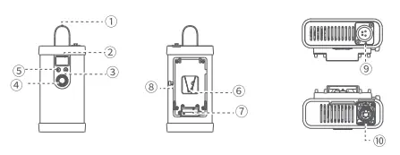
- Handle
- LCD Panel
- FX/
 Button
 - Adjust Dial
- Power Switch
- V-port Battery Slot
- Battery Compartment
- Battery Locking Ring
- DC Input Port
- DC Output Port
VL200I I/VL300I I Controller
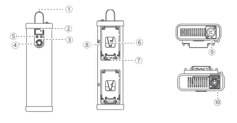
- Handle
- LCD Panel
- FX/Button
- Adjust Dial
- Power Switch
- V-port Battery Slot
- Battery Compartment
- Battery Locking Ring
- DC Input Port
- DC Output Port
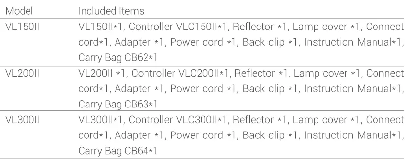
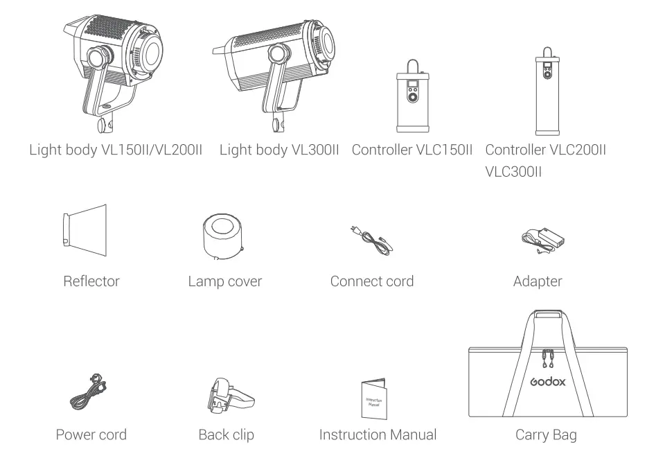
Included Items
Operation Instruction
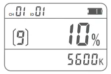
Power on/off
Connect the adapter and controller, long press the Power Switch to power the LED light on or off. 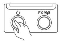
Mode selection:
Constant on mode/FX mode Constant on mode: The main interface is constant on mode, while the FX icon is not displayed on the left bottom of Turn the adJust dial for light brightness to change the value from 0% to 100%. 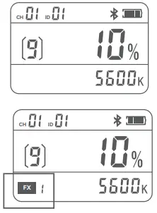
FX mode: Long press FX/ ![]() button to make the FX displayed on the left bottom of panel, it is FX icon mode.
button to make the FX displayed on the left bottom of panel, it is FX icon mode.
When the FX icon flashes, turn the adjust dial to select among the 8 light effects, then short press the FX,/,, button to confirm. Short press the FX,/,, button again can reselect the light effect.
Light effects table (8 types)
| Display | FXl | FX2 | FX3 | FX4 | FX5 | FX6 | FX7 | FX8 |
| Scenes | Flash 1 | Flash 2 | Flash | Storm 1 | Storm 2 | Storm 3 | Broken bulb | TV |
When the FX icon stops flashing, turn the adjust dial for light brightness to change the value from 0% to 100%. 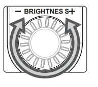
2.4GHz wireless setting
CH setting: Short press the FX,/![]() button once to make the CH icon flashes, then turn the adJust dial to choose among 01 to 32 channels. When the CH icon stops flashing, it means CH setting completed and automatically exited, while the CH icon flashes means short pressing FX/
button once to make the CH icon flashes, then turn the adJust dial to choose among 01 to 32 channels. When the CH icon stops flashing, it means CH setting completed and automatically exited, while the CH icon flashes means short pressing FX/![]() button 4 times can also automatically exit CH setting.
button 4 times can also automatically exit CH setting.
GR setting: Short press the FX/ ![]() button twice to make the GR icon flashes, then turn the adjust dial to choose among A to F or Oto 9 groups. When the GR icon stops flashing, it means GR setting completed and automatically exited, while the GR icon flashes means short pressing FX/
button twice to make the GR icon flashes, then turn the adjust dial to choose among A to F or Oto 9 groups. When the GR icon stops flashing, it means GR setting completed and automatically exited, while the GR icon flashes means short pressing FX/![]() button 3 times can also automatically exit GR setting.
button 3 times can also automatically exit GR setting.
ID setting: Short press the FX/![]() button three times to make the ID icon flashes, then turn the adJust dial to choose among 01 to 99 IDs or OF. When the ID icon stops flashing, it means ID setting completed and automatically exited, while the ID icon flashes means short pressing FX/
button three times to make the ID icon flashes, then turn the adJust dial to choose among 01 to 99 IDs or OF. When the ID icon stops flashing, it means ID setting completed and automatically exited, while the ID icon flashes means short pressing FX/![]() button twice can also automatically exit ID setting.
button twice can also automatically exit ID setting.
Power option
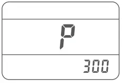
Press the power switch and FX/09 button at the same time in power off status to enter power option mode. Turn the adjust dial to choose power from 200, 250 and 300. The power is 300W by detault. It will exit from this mode automatically without operation for 5 seconds.
Note: This function is used for the situation that the battery enter protection states and cannot work due to some v-port battery doesn’t output the corresponding power in strong power output. When enter this mode, the output power of the light can be decreased and the battery can be loaded instead of being protected (this function only applies to VL3001|).
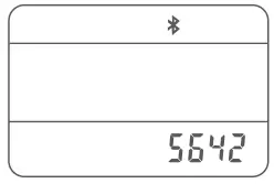
Bluetooth control Check Bluetooth MAC code
Check Bluetooth MAC code
Short press the FX/![]() button four times to make the Bluetooth icon and MAC code displayed, it is in Bluetooth setting interface.
button four times to make the Bluetooth icon and MAC code displayed, it is in Bluetooth setting interface.
Bluetooth reset
Long press the FX/![]() button in Bluetooth setting interface to make the Bluetooth icon flash, it means the Bluetooth is resetting. When the Bluetooth icon stops flashing means Bluetooth resetting is completed. It will exit from this mode automatically without operation for 10 seconds, short press the FX/t button to exit is also available.
button in Bluetooth setting interface to make the Bluetooth icon flash, it means the Bluetooth is resetting. When the Bluetooth icon stops flashing means Bluetooth resetting is completed. It will exit from this mode automatically without operation for 10 seconds, short press the FX/t button to exit is also available.
APP download
Scan the QR code to download the “Godox Light” mobile app. (It can be used on both Android and Apple systems) For specific operations, please refer to the “Help” manual of the mobile APP, which contains detailed tutorials.
Note: The first mobile device (mobile phone or tablet) can directly use the APP to control the light body. When replacing other mobile devices (mobile phones or tablets), the lamp body can be connected normally after Bluetooth reset.
Over-temperature Warning
- When the light body is at a high temperature, the CCT value on the LCD panel turns to “HP”, the light body still works normally.
- When the light body is over-temperature, the light turns out, and “HP” flashes on the LCD panel.
- When the light body changes from an over-temperature state to a normal temperature state, “HP on the LCD panel turns to the CCT value, and the light body restores its lighting
Illuminance data
| VL 15011 | |||||
| CCT | Testing Conditions | llluminance Unit | lm | 2m | 3m |
| 5600K | bare lamp | lux | 6100 | 1700 | 810 |
| fc | 570 | 160 | 76.0 | ||
| with reflector | lux | 76000 | 16000 | 5400 | |
| fc | 7000 | 1500 | 500 | ||
| VL200II | |||||
| CCT | Testing Conditions | llluminance Unit | lm | 2m | 3m |
| 5600K | bare lamp | lux | 7400 | 2100 | 1100 |
| fc | 700 | 190 | 100 | ||
| with reflector | lux | 88900 | 19000 | 8000 | |
| fc | 8300 | 180 | 750 | ||
| VL30011 | |||||
| CCT | Testing Conditions | llluminance Unit | lm | 2m | 3m |
| 5600K | bare lamp | lux | 11600 | 3500 | 1700 |
| fc | 1100 | 300 | 160 | ||
| with reflector | lux | 90000 | 20900 | 8800 | |
| fc | 8400 | 1950 | 820 | ||
Technical Data
| Model | VLl 50II | VL20DII | VL300II |
| Adapter Input | AC100V-240V 50/60Hz2A | AC100V-240V 50/60Hz 3.9A | AC100V-240V 50/60Hz 4.3A |
| Light Body Input | 35V=4.3A | 47.8V=4.2A | 50V=6A |
| V-port battery | Standard voltage:l 4.8V (optional) | ||
| Max. Power | 165W | 215W | 320W |
| CCT Range | 5600±200K | ||
| CH | 32 | ||
| GR | 16 groups (A,B,C,D,E,F,0-9) | ||
| ID | 99 | ||
| CRI | e96 | ||
| TLCI | e96 | ||
| Brightness Adjustment Range | 0% -100% | ||
| Working Temperature Range | -l0°C-40°C | ||
| U-type Bracket Adjustable Angle | 0″-360″ | ||
| Dimensions | Light Body: 270mm•l 75mm•212mm Controller: l l 4mm•59mm•258mm | Light Body: 270mm• l 75mm•212mm Controller: 60mm•l l 4mm•426mm | Light Body: 272mm•l 76mm•292mm Controller: 60mm•l l 4mm•426mm |
| Net Weight( ) | Light Body: 1.72kg Controller: 0.7kg | Light Body: 1.77kg Controller: 1.19kg | Light Body: 2.78kg Controller: 1.2kg |
FCC Statement
This device complies with part 15 of the FCC Rules. Operation is subject to the following two conditions
- This device may not cause harmful interference, and
- this device must accept any interference received, including interference that may cause undesired operation
Any Changes or modifications not expressly approved by the party responsible for compliance could void the user’s authority to operate the equipment
Note: This equipment has been tested and found to comply with the limits for a ClassB digital device, pursuant to part 15 of the FCC Rules. These limits are designed to provide reasonable protection against harmful interference in a residential installation. This equipment generates uses and can radiate radio frequency energy and, if not installed and used in accordance with the instructions, may cause harmful interference to radio communications. However, there is no guarantee that interference will not occur in a particular installation. If this equipment does cause harmful interference to radio or television reception, which can be determined by turning the equipment off and on, the user is encouraged to try to correct the interference by one or more of the following measures
- Reorient or relocate the receiving antenna.
- Increase the separation between the equipment and receiver.
- Connect the equipment into an outlet on a circuit different from that to which the receiver IS Connected.
- Consult the dealer or an experienced radio/TV technician for help
This equipment complies with FcC radiation exposure limits set forth for an uncontrolled environment. This equipment should be installed and operated with minimum distance 20cm between the radiator & your body.
Warning
Operating frequency: 2402MHz-2480MHz
Maximum EIRP Power: 5dBm
Declaration of Conformity
GODOX Photo Equipment Co.,Ltd. hereby declares that this equipment are in compliance with the essential requirements and other relevant provisions of Directive 2014/53/EU. In accordance with Article 10(2) and Article 10(10), this product is allowed to be used in all EU member states. For more information of DoC, Please click this web link: https://www.godox.com/DOC/Godox_VLILSeries_DOC.pdf.
The device complies with RE specifications when the device used at Omm from your body.
GODOX Photo Equipment Co.,Ltd.
Add..Building 2,Yaochuan Industrial Zone, Tangwei Community, Fuhai Street, Bao’an District, Shenzhen
518103,China Tel:+86-755-29609320(8062) Fax:+86-755-25723423 E-mail [email protected]
www.godox.com
Made in China 705-VL1 520-00


