UOTEK UT-6011 Series 1 Port Serial Device Server
Port Series Device Serial Server Overview
Product
The 1-port series device serial communication server, also called terminal server or serial server, is a converter between the asynchronous serial ports RS232/485/422 and Ethernet. It is a standalone intelligent device with CPU and embedded OS and complete TCP/IP protocol stack. It completes bidirectional transparent data transmission between RS232/485/422 and Ethernet, and allows RS232/485/422 serial devices to connect to the network immediately.
Product features: Support proxy server, can transmit data via Internet. Provides bi-directional transparent transmission of data, realizes serial port to TCP/IP function, users do not need to make any modification to the original system. Internal integration of ARP, IP, TCP, ICMP, SOCKET, UDP and other protocols. All programs provide Chinese interface, with setup wizard, easy to operate.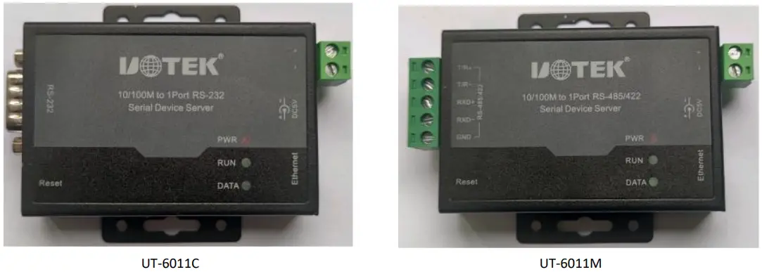
- port series serial server Factory IP address 192.168.1.199 Subnet mask 255.255.255.0
- Main Features
- Hardware features
- Chinese menu configuration interface, rich operation mode, to meet the application of different industries.
- Providing Windows virtual COM driver software.
- With a serial port, it can be connected to various serial devices such as terminal, Modem, barcode machine, cash register, ISDN, terminal adapter, serial printer and PC, and can realize remote control function.
- With Reset key, press for about 5 seconds to restore factory settings.
- With 10/100M adaptive Ethernet port.
- Each serial port provides complete signals, including RXD, TXD, RTS, CTS, GND.
- CPU 32-bit embedded 25MHz for strong overall performance.
Software Feature
- Support IP, ICMP, UDP, TCP and other protocols
- Support Windows extended serial port mode
- A complete set of extended serial port (com) drivers based on Windows platform, and a simple and easy-to-use Windows platform management program, which can drive up to 256 serial ports under Windows platform. In this mode, each serial port of the 1-port series serial server can be mapped to a local COM port of the Window host. This means that using these serial ports is just like using the local COM ports on the host computer, and it also means that all existing software or communication modules applied on the existing serial devices can be used directly without modification.
- ARP Support
The 1-port series serial server supports the standard ARP protocol. - Terminal server parameters configuration
- You can connect to the server for configuration through a special configuration tool, which allows you to apply the 1-port series serial server to your work very easily.
- Software Upgrade Support
The 1-port series serial server supports free software upgrade.
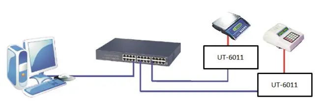
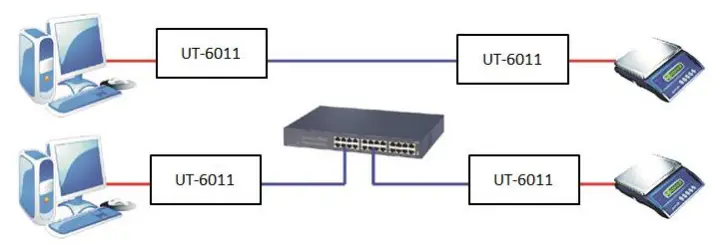
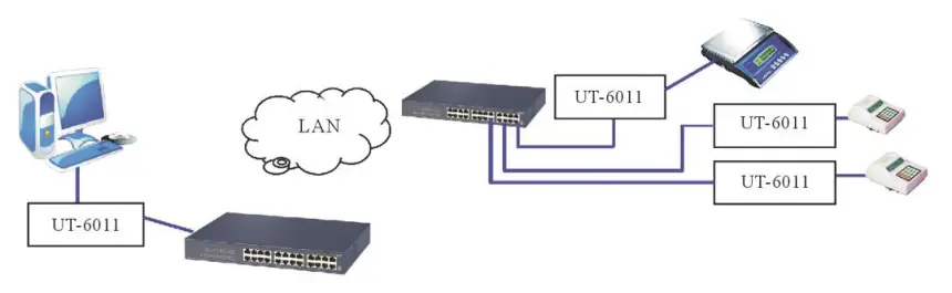
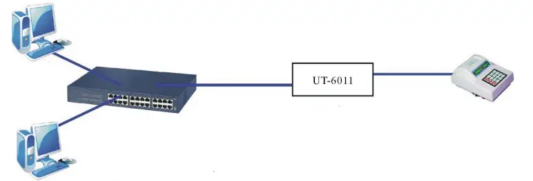
- Product application mode
- Virtual serial port mode (up to 256 serial ports)

- Point-to-point mode

- Point-to-Multipoint mode (up to 2 serial device servers)

- Multiple host mode (up to 2 hosts

- Virtual serial port mode (up to 256 serial ports)
Port Series Serial Device Server Installation Instructions
- Configuration Tool Description
- Configuration tool IP address search and change See Chapter 4 for details
- Virtual serial port software
- LED Indicator Description
Marking Model
TX/RX
RUN
PWR
UT-6011C Data transmission and reception indicator Run light Power light UT-6011M Data transmission and reception indicator Run light Power light - Serial port pin definition description
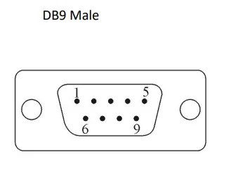
- 1-port serial device server DB9 connector pin definition.
DB9(PIN) RS-232C interface signal 1 NC 2 RXD 3 TXD 4 NC 5 GND 6 NC 7 RTS 8 CTS 9 NC 
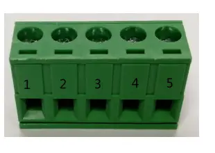
- 1-port serial device server RS-485/422 pin definition.

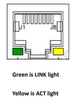
5.08 Terminal RS-485 RS-422 Description 1 T/R+ TXD+ Transmit/Receive Positive 2 T/R- TXD- Transmit/Receive Negative 3 N/C RXD+ Receive positive 4 N/C RXD- Receive negative 5 GND GND GND - 1-Port Serial Device Server RJ45 10/100M Network Port Pin Definition

RJ45 EIA/TIA 568B Definition Description EIA/TIA 568B 1 Orange white TX+ TX+ TX+ 2 Orange TX- TX- TX- 3 Green White RX+ RX+ RX+ 4 Blue N/C N/C N/C 5 Blue White N/C N/C N/C 6 Green RX- RX- RX- 7 Brown White N/C N/C N/C 8 Brown N/C N/C N/C
- 1-port Series Serial Device Server Technical Parameters
- Product Technical Parameter
Model UT-6011 Series Serial number 1 CPU 32bit 25MHZ RAM 2K bytes Serial port
Baud rate 110-921600bps Parity bits None, Odd, Even, Mark, Space Data bits 8 Stop bit 1, 2 Flow Control RTS/CTS Serial port form DB9 / terminal block Serial port protection Surge 10/700us common mode/differential mode 1000/500V Signal RS232:RXD/TXD/ GND /RTS/CTS、 RS485/422:TX+/RX+/TX-/RX-/GND Network port
Speed Auto-10/100M Network port form RJ45 Network port protection Embedded 2KV electromagnetic isolation, surge 10/700us common mode:1000V/differential mode 500V Software
Protocol ARP, IP, ICMP, UDP, TCP Virtual COM Windows XP/7/8/10 32/64bit Environment
Operating temperature -40~85°C Operating humidity 5~95% Storage temperature -40~85°C Storage humidity 5~95% Certification CE Power supply
DC4.75~5.25V 158mA@5Vmax
Appearance
Material Metal housing Dimension 79 mm×52 mm×21 mm - Product configuration table
Model
Serial Host
Power adapter
Tools
Product manual and warranty
Description
UT-6011C 1 1 个DC5V/1A 1 1 RS-232 DB9 male output UT-6011M 1 1 个DC5V/1A 1 1 RS-485/422 5.08 terminal output
- Product Technical Parameter
1-port serial server configuration tool operating instruction
- Main screen.
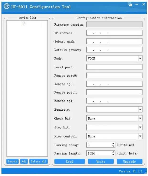
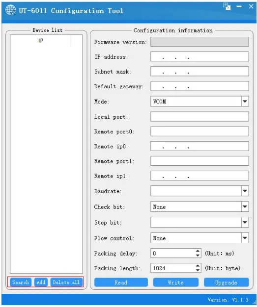
Open the CD or configuration tool, double click to open the serial server configuration tool, the following interface
Note: The main interface of the configuration tool mainly includes two parts: the device list and configuration information, and the version number of the current tool at the bottom right, subject to actual use - Device List:

- There are three main functions in the device list for ip address processing
- Search: After confirming that the serial server is connected correctly and running normally, click Search to get the current ip address and MAC address of the device
Add: Click Add, enter the ip address, you can directly add the ip to the list of devices - Delete: select the ip address you want to delete, you can move the ip out of the device list, the default is to delete all
- Note: When the device is not fully operational or failure, the search ip will not be successful
- Search: After confirming that the serial server is connected correctly and running normally, click Search to get the current ip address and MAC address of the device
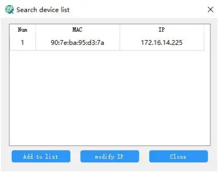
- about the search

By searching the device, after being selected, you can add to the device list and modify the ip address and other operations, the default add to all add
(This function is mainly to facilitate the user to serial port server and host ip in the same network segment, in order to read and write configuration) - Configuration Information

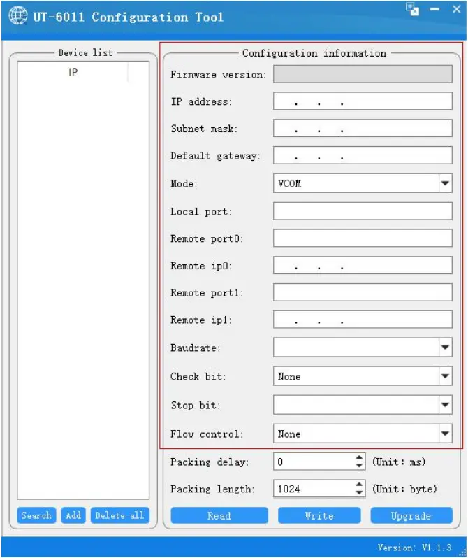
- Configuration Information Description
Configuration Information Description Firmware Version Serial device server firmware version, not changeable IP Address Serial device server device IP address, changeable Subnet Mask Serial device server device subnet mask, changeable Default Gateway Default gateway for serial device server, changeable Mode The current mode of the serial device server, optionally Local port number Serial device server device port number, changeable Remote port Remote device port number, changeable Remote IP Remote device IP address, changeable Baud rate Baud rate setting for serial server devices, selectable Parity bits Serial device server parity bit, optionally Stop bit Serial device server device stop bit, selectable Flow Control Serial device server flow control, optionally - Configuration function description
- Configuration Information Description
- There are three main functions in the device list for ip address processing
Read configuration
After confirming that the serial server is connected correctly and running normally, select the serial server device and click Read Configuration to get the configuration information as follows.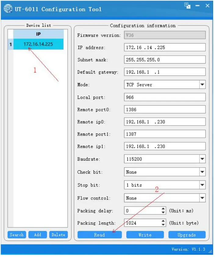
Write configuration
First select the configuration information that can be changed and selected to make changes
After the changes are confirmed, click Write Configuration, which will save the configuration information to the serial server device
Firmware Upgrade:Different from the application mode upgrade mode, click and confirm will enter the upgrade interface as shown below, you can upgrade the device firmware (this mode will interrupt the device that is communicating)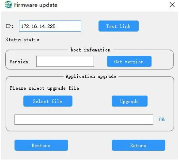
Note: About the upgrade
Click test link, it shows that the link is normal, then you can select the upgrade file, click upgrade after selection, when the progress is completed 100%, the upgrade is successful. In addition, the firmware can support restoring factory settings in version V26 or above, all configurations will be restored to the factory state.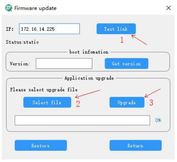
Note: The upgrade status will be different from the application status. When the device is in the upgrade status, please click back to the application mode after the upgrade is completed, wait until you enter the application mode, and then operate to avoid the device abnormality.
Device Mode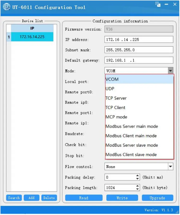
Currently the device supports nine specific modes such as VCOM, UDP, TCP Sever, TCP Client, MCP, Modbus, etc. The default mode is VCOM and the port number is fixed at 966
| Mode | Mode Description |
| VCOM | VCOM is a virtual serial port mode, you can virtualize the serial server as a serial device for communication, the port number in this mode is fixed at 966 |
| UDP | The UDP mode of operation is subordinate to the UDP protocol, a connectionless mode that provides a simple, unreliable, thing-oriented messaging service |
| TCP Mode | The TCP mode of operation is subordinate to the TCP protocol, which is a connection-oriented, reliable and transparent transmission service, including the TCP Sever and TCP Client modes; in both modes, the corresponding IP and port numbers can be filled in to communicate with each other. |
| Modbus Mode | Modbus operating mode is subordinate to the Modbus protocol and is an operating mode that supports the Modbus protocol |
This note focuses on the virtual serial port mode VCOM
Virtual serial port mode
Double click on the virtual serial port software VCOM to get the following main interface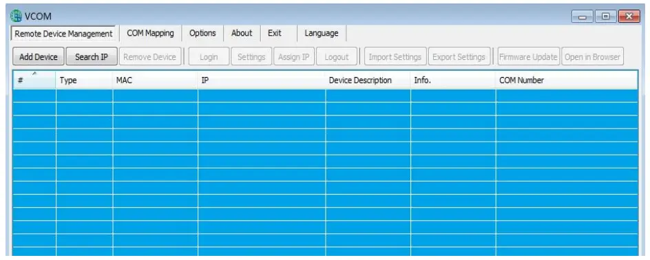
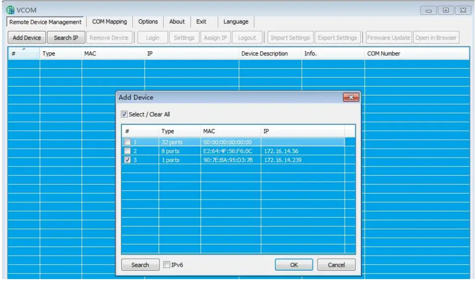
Under the Remote Device Management menu, click Add Device in the first step to get the following screen, click Search in the second step to get the following devices, and in the third step, check our devices and add them. 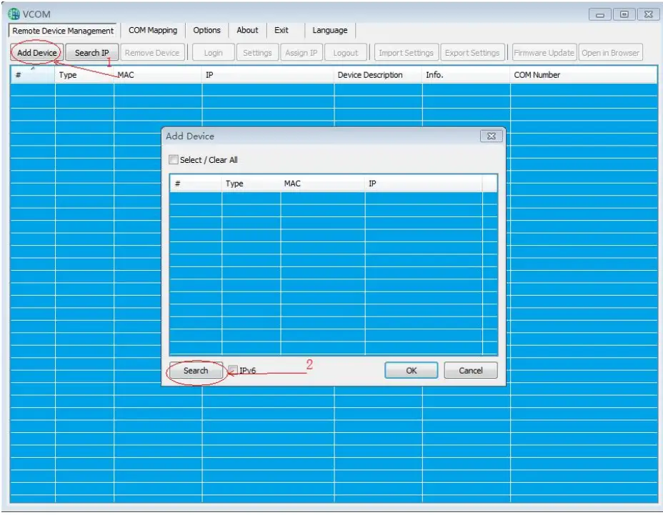
 Click COM Mapping to create a virtual serial port, starting from COM1 by default, you can click COM1 to change the serial port number
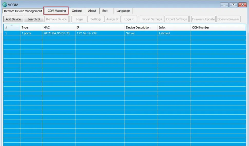
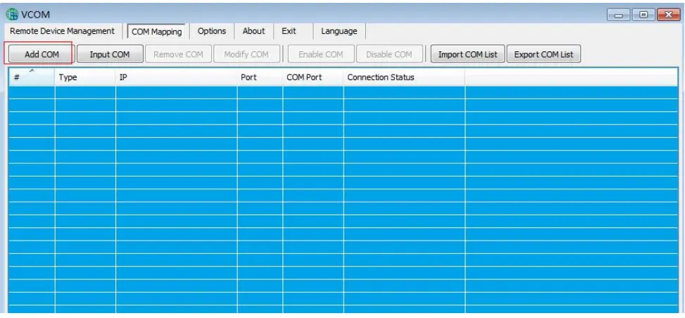
Create successfully
Under Device Manager, you will see that there is already a serial port number Select the serial port number for normal communication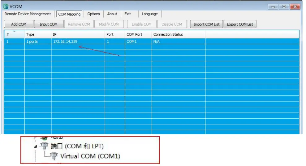
1-Port Series Serial Device Server Troubleshooting Instructions
- Click search can not search the IP address of the serial server
- , first check whether the physical connection is normal, the network cable and power supply is connected, observe the power indicator, LINK light, ACT light is normal (connected to the 10M network, this light does not light, 100M light)
- the host network card is available, can not communicate with other local or other hosts.
- close all the tools and software that can block the broadcast packet (do not open the firewall that comes with the system)
Your Reliable Partner in Industrial IoT
- Cannot read or write configuration
- Ensure the normal operating status of the network (whether the ACT light and RUN light are normal)
- Ensure that the serial server device and the connected host are in the same network segment, and whether the IP can ping through
- Ensure that the serial server is in application mode
- if the above can not solve the problem try to power off and restart, if necessary, restore factory settings
- Cannot send and receive data
- Ensure that the serial port can be opened normally
- Observe whether the system light is flashing fast or slow, flashing fast for the data sent and received, such as no flashing fast check the connection between the serial port and the upper network, and the bottom serial device to check the wiring
- Forget the previous configuration information
- Determine the configuration information by reading the configuration, if the ip address is not remembered, then you can search for
- Transmitting and receiving data is messy code
- Check if the wiring is correct,our 485 wiring is 1A+,2B-.
- Check if the line distance has exceeded the standard distance and the quality of the line (also by lengthening the line transceiver or optical isolation)
- Check whether the baud rate set matches the bottom device
- Separate from the client’s top software, use the network or serial debugging assistant can receive normal data, if you can receive normal data, may not be compatible with the top software
- If none of the above ways can solve your problem, please contact the manufacturer
Annexes
Virtual Serial Port Software Description
Software Installation
Before installing the virtual serial software, make sure to close the WINDOWS firewall, and all antivirus software Then double click and wait until the installation is ready to finish 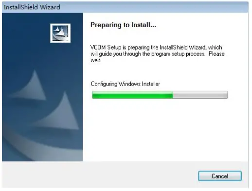 Click Next
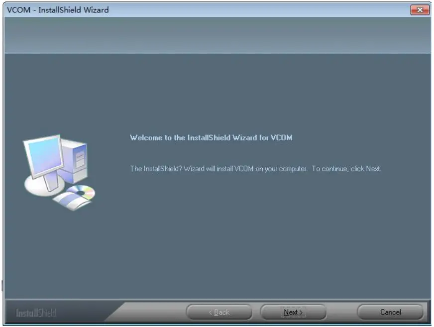
Select the installation location and click Next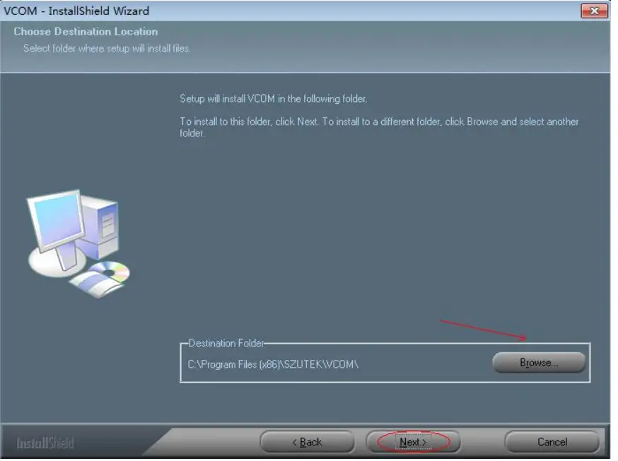
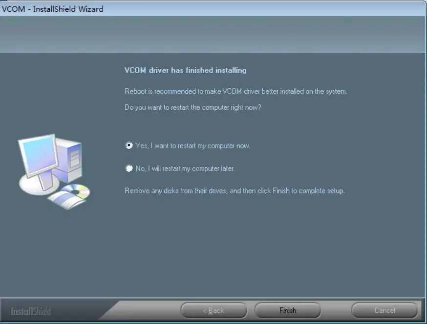
Click Yes and wait for the installation to complete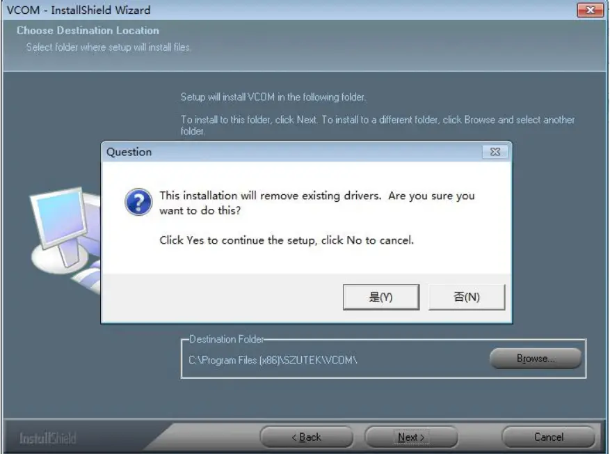
Click to select reboot, you can use the shortcut to enter the software operation after completion