
intelbras AMT 8000 LITE Monitored Alarm Center

AMT 8000 LITE
Alarm center
Congratulations, you have just purchased a product with Intelbras quality and safety.
The AMT 8000 LITE wireless alarm center features advanced technology and is easy to program. All 8000 series devices can be connected, exchanging encrypted information, for increased system security. The system has differentials such as a high-performance wireless device communication (bidirectional) with a range of up to 600 meters without barriers and direct sight, GPRS, GSM, and Ethernet type connections to provide easier monitoring reporting to 2 IPs (monitoring companies) plus the Intelbras Cloud connection using initially the random remote access password indicated along with the QR code label that also contains the MAC.
The AMT 8000 LITE center has remote software (firmware) updates, using Ethernet communication to download the firmware version. In addition to this option, the center can also be updated using the BootLoader resource. For this, it is necessary to have the Atualizador 8000 software previously installed on your computer.
ATTENTION: this product comes with a factory default password. For your safety, it is ESSENTIAL that you change it as soon as you install the product and ask your technician about the configured passwords, which users have access, and the recovery methods.
Care and Safety
- Follow all instructions in the manual to install and handle the product.
- Install in environments not susceptible to factors such as rain, fog and water splashes.
- Wireless communication technology, when exposed to environments with high power radiation, may suffer interference and and have its performance impaired. Example: locations near TV towers, AM/FM radio stations, amateur radio sta-tions, etc.
- Do not install the alarm center and its accessories near radio frequency equipment such as routers, repeaters, and/or Wi-Fi signal amplifiers. The center and its devices must maintain a minimum distance of 2 meters from this equipment.
- Do not install the alarm center in front of air conditioning or heating equipment.
- Do not expose to direct sunlight.
- Clean only the outside of the device, using a damp cloth (do not use chemical solvents).
- Do not subject the device to excessive pressure or shock/drops.
- Check that at the installation site, the LED indicator of the devices flashes green when activated.
- Avoid installation on metallic surfaces so as not to weaken the transmission signal between the system’s devices.
- The installation and configuration of the center and the other products that make up this system must be performed by a qualified professional.
- Perform periodic tests on it, in order to validate weather conditions, battery level and other factors, so that the site monitored by the system is always in proper operating condition.
- LGPD – General Personal Data Protection Act: Intelbras does not access, transfer, collect or otherwise process any perso-nal data from this product.
Installation
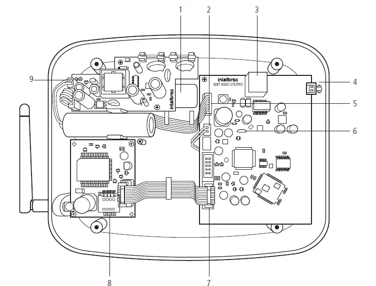
- Opening to pass the network cable (Ethernet).
- Integrated siren connection.
- Connector for Ethernet network cable.
- Key for registration of wireless devices.
- Input for power supply flat cable.
- Micro-USB connector to update the firmware of the alarm center.
- Flat cable connector for XG 2G / XG 3G modules.
- Connector for SIM card 1 and SIM card 2.
- Input connector for the two-way battery cable.
Note: the XG 2G and XG 3G modules are compatible with most national GSM operators with 2G and 3G technology.
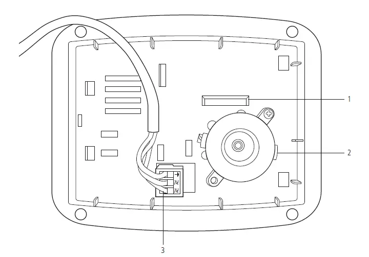
- Tamper-proof key.
- Integrated siren.
- Connector for AC power supply.
Attention: be careful not to reverse the position of the ground wire.
Attention: The alarm center and AMT 8000 LITE do not have an auxiliary output to supply power to other devices and no connection point on the center’s boards (center, GPRS card, or power supply) should be used for this functionality, since in addition to damaging the alarm center and its accessories, the devices that are connected may be damaged because the alarm center operates with variable voltages.
Enter programming mode
Note: to modify the technical parameters of your alarm center, it is recommended to contact a qualified technician.
Enter programming mode
To modify any of the center’s operating parameters, always enter the programming mode. To do this, enter the following sequence:
Enter + Password (Master or Installer Password)
Exit programming mode
To exit programming mode, enter the master password or the installer password (the same password used to access programming mode).
Quick programming reference
This quick reference assumes that the center is in programming mode and presumes that the entire manual has been read and the result of each function is known.
Manual available on the website www.intelbras.com.br.
When accessing the programming mode, editing or viewing some programming through the keyboard, if the sequence or password is accepted, 2 confirmation beeps will be emitted, otherwise, a long error beep will be emitted, in which case you must start entering the password or command again.
Wireless devices
Attention: If it is not possible to register the device to the alarm center, reset it by pressing the synchronization button for approximately 10 seconds until the device LED indicator flashes red twice. This process ensures that the device will not be linked to any other system, the keypad will display the message Keypad not registered and then the message Register keypad, indicating that it can be registered again.
Registration by synchronization key
Press and release the synchronization key of the alarm center and wait until LED 3 lights up continuously, indicating that the center is ready for registration of wireless devices. When you have finished registering all devices, press the synchronization key of the alarm center again and check that LED 3 is out of Continuous mode (blinking indicating normal operation), showing that the center has exited wireless device registration mode.
Maximum device capacity:
- Wireless keyboardss 16
- Remote controls 98
- Wireless sensors 64
- Wireless sirens 16
- Repeaters 04
- PGM actuators 16
Note: when physically deleting the devices, they must be deleted from the center’s memory through programming. Otherwise, the wireless device supervision fault will be generated for these devices.
Keyboard commands for wireless devices
Keyboard
- Change the system language Enter + 854 + I + Enter
- I = 0: Portuguese
- I = 1: Spanish
- I = 2: English
Note: function available as of version 1.0.1 of the XAT 8000 keyboard.
- Register the wireless keyboard
Enter + 620 + NT + Enter + Actuate the keypad by pressing the synchronization key.
NT = keyboard number from 01 to 16. - Delete wireless keyboards
Enter + 720 + NT + Enter.
NT = keyboard number from 01 to 16.
- Register the wireless keyboard
- Keyboard firmware preview
Enter + 642 + TT + Enter
TT = 2-digit keypad number
Note: function available for keyboards from version 2.0.0 onwards. - Wireless keyboard partitioning
Enter + 223 + NT + PP + Enter.
NT = keyboard address from 01 to 16.
PP = partition from 00 to 16 (00 = common address for all zones and 01 to 16 the individual partitions of the center). - Change messages
Enter + GM + Active + User, device, partition or zone + Enter.
GM = group of messages from 1 to 8.
User, device, partition or zone = in case of messages for zone 1 to 64, device from 01 to 16, partition from 01 to 16 and in case of user from 00 to 99.
| Description | Message group | User, device, partition or zone |
| Alarm center name | 1 | 00 |
| Users | 2 | 00 to 99 |
| Zones | 3 | 01 to 64 |
| Partitions | 4 | 01 to 16 |
| PGM | 5 | 01 to 16 |
| Keyboards | 6 | 01 to 16 |
| Sirens | 8 | 01 to 16 |
- Resetting messages
Enter + 1 + Disable + Enter.
Note: resets all messages of the center to factory defaults for the selected language. - Panic key
Enter + 540 + P + Enter. - P = 0: Disabled.
- P = 1: Audible panic.
- P = 2: Silent panic.
- P = 3: Fire panic.
- P = 4: Medical emergency.
Remote control
- Remote control registration
Enter + 60 + NU + Enter + Actuate the control by pressing one of the keys. NU = user number from 00 to 97. - Delete remote control
Enter + 70 + NU + Enter.
NU = user number from 00 to 97. - Remote control key functions
Enter + 65 + T + NU + FC + Enter.
T = control key from 1 to 3.
NU = user number from 00 to 97.
FC = function of the key that will be linked to the selected key from 00 to 66.
| 00 | Disabled |
| 01 | Atv/Dtv all partitions |
| 02 | Only activates all partitions |
| 03 | Only disables all partitions |
| 04 | Atv/Dtv all partitions in Partial mode |
| 05 | Only arms in Partial mode |
| 06 | Panic with siren |
| 07 | Silent panic |
| 08 | Fire panic |
| 09 | Medical emergency |
| 10 | N/A |
| 11 | Atv/Dtv only Partition 1 |
| 12 | Atv/Dtv only Partition 2 |
| 13 | Atv/Dtv only Partition 3 |
| 14 | Atv/Dtv only Partition 4 |
| 15 | Atv/Dtv only Partition 5 |
| 16 | Atv/Dtv only Partition 6 |
| 17 | Atv/Dtv only Partition 7 |
| 18 | Atv/Dtv only Partition 8 |
| 19 | Atv/Dtv only Partition 9 |
| 20 | Atv/Dtv only Partition 10 |
| 21 | Atv/Dtv only Partition 11 |
| 22 | Atv/Dtv only Partition 12 |
| 23 | Atv/Dtv only Partition 13 |
| 24 | Atv/Dtv only Partition 14 |
| 25 | Atv/Dtv only Partition 15 |
| 26 | Atv/Dtv only Partition 16 |
| 27 | N/A |
| 28 | N/A |
| 29 | N/A |
| 30 | N/A |
| 31 | Atv/Dtv partial mode only for Partition 1 |
| 32 | Atv/Dtv partial mode only for Partition 2 |
| 33 | Atv/Dtv partial mode only for Partition 3 |
| 34 | Atv/Dtv partial mode only for Partition 4 |
| 35 | Atv/Dtv partial mode only for Partition 5 |
| 36 | Atv/Dtv partial mode only for Partition 6 |
| 37 | Atv/Dtv partial mode only for Partition 7 |
| 38 | Atv/Dtv partial mode only for Partition 8 |
| 39 | Atv/Dtv partial mode only for Partition 9 |
| 40 | Atv/Dtv partial mode only for Partition 10 |
| 41 | Atv/Dtv partial mode only for Partition 11 |
| 42 | Atv/Dtv partial mode only for Partition 12 |
| 43 | Atv/Dtv partial mode only for Partition 13 |
| 44 | Atv/Dtv partial mode only for Partition 14 |
| 45 | Atv/Dtv partial mode only for Partition 15 |
| 46 | Atv/Dtv partial mode only for Partition 16 |
| 51 | PGM 01 |
| 52 | PGM 02 |
| 53 | PGM 03 |
| 54 | PGM 04 |
| 55 | PGM 05 |
| 56 | PGM 06 |
| 57 | PGM 07 |
| 58 | PGM 08 |
| 59 | PGM 09 |
| 60 | PGM 10 |
| 61 | PGM 11 |
| 62 | PGM 12 |
| 63 | PGM 13 |
| 64 | PGM 14 |
| 65 | PGM 15 |
| 66 | PGM 16 |
Wireless sensors
- Register wireless sensors
Enter + 61 + ZZ + Enter + Actuate the sensor by pressing the synchronization key.
ZZ = zone to which the sensor will be linked from 01 to 64. - Delete wireless sensors
Enter + 71 + ZZ + Enter.
ZZ = zone to which the sensor will be linked from 01 to 64. - Adjustment of the wireless infrared sensors
Enter + 66 + ZZ + S + L + M + Enter.
Z = zone from 01 to 64.
S = Sensitivity from 0 to 3, where 0 = minimum sens. / 1 = normal sens. / 2 = intermediate sens. / 3 = maximum sens. L = Sensor LED, where 0 = Off / 1 = On.
M = Sensor operating mode, where 0 = Economical / 1 = Continuous.
Note: for the XAS 8000 and TX 8000 the Sensitivity, Sensor LED and Operation mode settings are allowed by the center, but only the LED setting is accepted by the XAS 8000 and TX 8000.
- Wireless sensor test
Enter + 52 + Enter + Actuate sensor. - Disable sensor tamper
Enter + 78 + X + Enter.
X = Zone group 0 to 6 - Disable digital tamper of IVP 8000 EX sensor Enter + 79 + X + Enter.
X = Zone group de 0 a 6 - Restoring the digital tamper of the IVP 8000 EX sensor Enter + 543 + ZZ+ Enter.
ZZ= 2-digit zone number. - Display of sensors firmware
Enter + 641 + ZZ + Enter.
ZZ = 2-digit zone number.
Note: function is available for devices with version 2.0.0.0 and higher. For devices with a version lower than 2.0.0.0, 0.0.0.0 will be displayed.
Wireless sirens
- Register wireless sirens
Enter + 621 + NS + Enter + Actuate the siren by pressing the synchronization key.
NS = siren number from 01 to 16. - Delete wireless sirens
Enter + 721 + NS + Enter.
NS = siren number from 01 to 16.
Note: it is not possible to delete the position of the integrated siren. - Partitioning of wireless sirens
Enter + 222 + NS + PP + Enter.
NS = siren number from 01 to 16.
PP = partition from 00 to 16 (00 = common address for all zones and 01 to 16 the individual partitions of the center). - Enable/disable siren beep on system activation/deactivation
Enter + 510 + Enter + Key 3 + Enter. - Enable/disable siren beep per partition
Enter + 224 + GP + Enter.
GP = group of partitions, with partitions 01 to 10 in group 0 and partitions 11 to 16 in group 1. - Enable/disable integrated siren
Enter + 541 + Enter
After the command, use the 1 key on the keyboard to enable or disable the function and press the Enter key to confirm. - Change siren time
Enter + 41 + TS + Enter.
TS = siren time from 01 to 99.
Note: factory default 5 minutes, and if 00 is set in the command, an error beep will be emitted.
- Register RF range amplifier (REP 8000 repeater)
Enter + 622 + NA + Enter + Actuate the amplifier by pressing the synchronization key. NA = amplifier number from 01 to 04. - Delete RF Range Amplifier (REP 8000 Repeater)
Enter + 722 + NA + Enter
NA = amplifier number from 01 to 04. - Repeater firmware verification
Enter + 644 + RR + Enter.
RR = 2-digit repeater number.
Route change by command - Search for new route sensors
Enter + 544 + ZZ + Enter.
ZZ = 2-digit zone number. - XAT 8000 new route search
Enter + 545 + TT + Enter.
TT = 2-digit keypad number. - PGM 8000 new route search
Enter + 547 + PP + Enter.
PP = 2-digit PGM number.
Note: function available for devices from version 2.0.0 onwards. - Register Actuator PGM 8000
Enter + 623 + PGM + Enter + Actuate the Actuator by pressing the synchronization key. PGM = Actuator number from 01 to 16. - Delete PGM 8000 actuator
Enter + 723 + PGM + Enter.
PGM = Actuator number from 01 to 16.
Firmware verification of PGM 8000 actuators
Enter + 646 + PP + Enter.
PP = 2-digit PGM number.
Note: function available for devices from version 2.0.0. - PGM 8000 actuator functions
Enter + 50 + PGM + Enter + M + E + Enter.
PGM = PGM number from 01 to 16.
M = PGM operation mode from 0 to 9 (0 = on/off, 1 to 8 = pulse and 9 = programmed time). E = Event that actuates PGM from 00 to 13.
| 00 | External actuation (applications) |
| 01 | Password actuation (passwords from 51 PGM01 to 66 PGM16) |
| 02 | System activation |
| 03 | System deactivation |
| 04 | Medical emergency: |
| 05 | Event communication failure |
| 06 | N/A |
| 07 | Siren problem: |
| 08 | Trigger |
| 09 | Trigger or silent panic |
| 10 | Fire zone triggering: |
| 11 | Zone 1 opening |
| 12 | Remote control |
| 13 | Activation / deactivation by time |
- Time programmed for PGM 8000 to remain on Enter + 560 + PGM + T + Enter.
PGM = PGM number from 01 to 16.
T = Time from 01 to 99 minutes. - Days for Programmed auto-activation of PGM 8000 Actuator Enter + 836 + PGM + Enter.
PGM = PGM number from 01 to 16.
After the command, with the keyboard keys, select the days of the week from 1 to 7, where 1 = Sunday, 2 = Monday, 3 = Tuesday, 4 = Wednesday, 5 = Thursday, 6 = Friday, 7 = Saturday and 8 = holiday and confirm with Enter.
- Time of auto-activation of the PGM 8000 Actuator Enter + 561 + PGM + D + HH + MM + Enter.
PGM = PGM number from 01 to 16.
D = day of the week from 1 to 7 (1 = Sunday, 2 = Monday, 3 = Tuesday, 4 = Wednesday, 5 = Thursday, 6 = Friday, 7 = Saturday and 8 for holidays).
HH = hours from 00 to 23.
MM = minutes from 00 to 59.
- Days for programmed auto-deactivation of the PGM 800 Actuator Enter + 837 + PGM + Enter.
PGM = PGM number from 01 to 16.
After the command, with the keyboard keys, select the days of the week from 1 to 7, where 1 = Sunday, 2 = Monday, 3 = Tuesday, 4 = Wednesday, 5 = Thursday, 6 = Friday, 7 = Saturday and 8 = holiday and confirm with Enter.
- Time of auto-deactivation of the PGM 800 Actuator Enter + 562 + PGM + D + HH + MM + Enter.
PGM = PGM number from 01 to 16.
D = day of the week from 1 to 7 (1 = Sunday, 2 = Monday, 3 = Tuesday, 4 = Wednesday, 5 = Thursday, 6 = Friday, 7 = Saturday and 8 for holidays).
HH = hours from 00 to 23.
MM = minutes from 00 to 59.
- Holidays for auto-activation/auto-deactivation of the PGM 800 Actuator Enter + 564 + PGM + F + DD + MM + Enter.
PGM = PGM number from 01 to 16.
F = holiday memory number 0 to 9.
DD = day from 01 to 31.
MM = month from 01 to 12. - PGM 8000 actuator association for partitioning
Enter + 563 + PGM +PP + Enter.
PGM = PGM number from 01 to 16.
PP = partition from 01 to 16.
Reset wireless devices - Delete all registered wireless devices
Enter + 7 + Disable + Enter.
1 All wireless devices in the switchboard will be unregistered, including the keypad that is being used. - RF channel change
Enter + 630 + RF + Enter. RF = channels from 08 to 11.
Attention: when changing the alarm center channel, all devices registered to the alarm center (except the remote control) must have the synchronization key pressed to direct the device to the new channel, otherwise they will not communicate with the alarm center.
Ethernet/GPRS connection
- Ethernet: An RJ45 type cable must be installed in the center with the Ethernet signal coming from a router, switch or directly from the signal received at the installation site. Check with the Internet provider whether the port used allows external access.
- GPRS: with the GPRS connection enabled in the alarm center, the reporting of events and connections will use this channel, and for this purpose the XG 2G or XG 3G module must be implemented together with the center and chips with access to a data packet must be installed. To communicate via GPRS, the chip (SIM card) must be enabled for a packet data plan. It is not necessary to enable voice service. Consult the operator to acquire the most suitable plan for the information traffic of the alarm center.
In order to establish the GPRS connection with the alarm center, the following configurations must be made.
- Enable chips
Enter + 832 + Enter. - After the command, use the keyboard keys to enable options 1 (chip 1) and 2 (chip 2).
Program login
Enter + 822 + O + Enter, where O = 1 or 2 (Operator 1 or Operator 2)
After the command, type the user name (depending on the operator used) and then press the Enter key to confirm. - Program password
Enter + 823 + O + Enter, where O = 1 or 2 (Operator 1 or Operator 2)
After the command, type the password (depending on the operator used) and then press the Enter key to confirm. - Program APN
Enter + 824 + O + Enter, where O = 1 or 2 (Operator 1 or Operator 2)
After the command, type the APN (depending on the operator used) and then press the Enter key to confirm. Program the PIN (Personal Identification Number)
If you want to use the PIN, perform the command in sequence, otherwise go to the next command.
If the PIN is wrong, the chip will be blocked.
Enter + 825 + O + PIN number with 4 digits + where O = 1 or 2 (Operator 1 or Operator 2))
After selecting the type of connection to be used, it is necessary to carry out the following steps to verify/configure some points of the connection, such as verifying the IP address that the center is operating from.
IP address of the center
Enter + 8120 + Enter.
The IP address of the center will be displayed if DHCP is enabled, if DHCP is disabled you can manually enter the IP address of the center.
- Program DHCP
If you do not have a DHCP server or do not want to use this option, proceed to the next step, otherwise, type the next command and the following ones as well. - Enter + 831 + Enter.
After the command, using the keys on the keyboard, enable option 1 (dial 1) and press the Enter key to confirm. To disable, leave option 1 unchecked. - Program the network mask
Enter + 8130 + Enter.
After the command, type the netmask number and press the Enter key to confirm.
Program the gateway - Enter + 8140 + Enter.
After the command, type the network gateway number and press the Enter key to confirm. - Program DNS servers for Ethernet
Enter + 815 + S + Enter, where S = 1 or 2 (Server 1 or Server 2).
After the command, type the DNS1 server number and press the Enter key to confirm.
Remote update
To download/check out a new version
Enter + 9922 + Enter.
If there is a version available for download, the message Download Wait will appear and the download will start, which will take between 3 and 5 minutes (depending on the network). If the center does not have a version to download, the message Download failed will appear.
Install the download version
Enter + 9933 + Enter.
The newly downloaded version will be installed and the records and programming of the center will not be lost. To check the software version of the center, access the Menu and using the arrow keys access the Version of the center to display it.
Note: the center must be connected to the Ethernet. It is not possible to download/update the software through the GPRS connection due to the download speed of the connection and the excessive consumption of the packet used.
Passwords
Password programming 1 (exclusive programming for the programmer user)
- Change passwords for users of positions 98 and 99
Enter + 20 + NU + PASSWORD + Enter.
NU = user number 98 or 99.
PASSWORD = password to be programmed containing 4 or 6 digits. - Delete the user’s password from position 98
Enter + 20 + 98 + Enter.
The password for position 99 cannot be deleted.
Password programming 2 (exclusive programming for the master user)
- Change/create passwords for users in positions 00 to 97. Enter + 20 + NU + PASSWORD + Enter.
NU = user number from 00 to 97.
PASSWORD = 4 or 6 digit password to be programmed. - Delete password for users in positions 01 to 97
Enter + 20 + NU + Enter.
NU = user number from 01 to 97.
The password for position 00 cannot be deleted.
Password permissions
- Define permission for password partitioning
Enter + 21 + NU + GP + Enter.
NU = n user number from 01 to 96.
GP = group of partitions, with partitions 01 to 10 in group 0 and partitions 11 to 16 in group 1. - Define permission only for activation or permission for bypassing
Enter + 2 + P + GS + Enter + Select password + Enter.
P = permission setting, 5 active only and 6 bypass permission.
GS = group of passwords from 0 to 9, with group 0 going from 01 to 10, group 1 from 11 to 20 and so on closing with group 9 from 91 to 97.
- Define permission for partial mode
Enter + 221 + GS + Enter + Select password + Enter.
GS = group of passwords from 0 to 9, with group 0 going from 01 to 10, group 1 from 11 to 20 and so on closing with group 9 from 91 to 97.
Zone configuration
Enable/disable zones
Enter + 30 + G + Enter.
G = group of zones from 0 to 6.
After entering the command, using the keyboard keys, enable/disable the corresponding zones for the group and press the Enter key to confirm.
Enable partial mode
Enter + 02 + G + Enter.
G = group of zones from 0 to 6.
After entering the command, using the keyboard keys, enable/disable the corresponding zones for the group and press the Enter key to confirm. It is also necessary that the passwords have the Stay mode permission.
Zone functions
Enter + 3 + F + G + Enter.
F = functions of zones 1 to 6.
G = group of zones from 0 to 6.
After entering the command, using the keyboard keys, enable/disable the corresponding zones for the group and press the Enter key to confirm.
| Zone functions | |
| 1 | Timed |
| 2 | Follower |
| 3 | 24 hours |
| 4 | Panic |
| 5 | Medical emergency |
| 6 | Fire |
Zone operation mode
Enter + 0 + MP + G + Enter.
MP = mode of zones 7 or 8.
G = zone group 0 to 6.
After entering the command, using the keyboard keys, enable/disable the corresponding zones for the group and press the Enter key to confirm.
| MP | Operation Mode |
| 7 | Silent |
| 8 | Normally open contact |
Automatic Zone Cancellation Enter + 53 + N + Enter.
N = number of triggers from 0 to 9.
On input
Enter + 09 + ZZ + Enter
ZZ= zones 01 to 64
On input partition
Enter + 516 + GP + Enter
GP = group of partitions, with partitions 01 to 10 in group 0 and partitions 11 to 16 in group 1.
Permission to activate and/or deactivate the oninput
Enter + 518 + Enter
Tecla 2 – Permission to activate
Tecla 3 – Permission to deactivate
Partition
Enable partition
Enter + 510 + Enter + Select option 1 + Enter.
Zone partitioning
Enter + 01 + ZZ + PP + Enter.
ZZ = zone from 01 to 64.
PP = partition from 01 to 16.
- Define permission for password partitioning
Enter + 21 + NU + GP + Enter.
NU= user number from 01 to 96.
GP = group of partitions, with partitions 01 to 10 in group 0 and partitions 11 to 16 in group 1.
Attention: In addition to the programming points mentioned above, it is necessary to create/define user passwords (topic 3.4. Passwords) as well as register wireless controls for access (topic Remote Control). It is also necessary to define the partitioning of keyboards (topic Keyboard) and sirens (topic Wireless Sirens).
Timings
Input timing
Enter + 42 + PP + TTS + Enter.
PP = partition from 01 to 16 (center without partition, use PP = 01).
TTS = time from 000 to 255 seconds.
- Beep adjustment on input timing Enter + 542 + A + Enter.
A= 0 – Disabled
1. Low
2. Medium
3. High
Output timing
Enter + 44 + PP + TTS + Enter.
PP = partition from 01 to 16 (center without partition, use PP = 01).
TTS = tempo from 000 to 255 seconds (beeps will be emitted only through the keyboard and not through the integrated siren).
Disable the output beep
Enter + 514 + Enter + Key 8 + Enter.
Temporary configuration of the alarm center
Clock
Enter + 400 + HH + MM + SS + Enter.
HH = hours from 00 to 23.
MM = minutes from 00 to 59.
SS = seconds from 00 to 59.
Calendar
Enter + 401 + DD + MM + AA + Enter.
DD = day from 01 to 31.
MM = month from 01 to 12.
YY = year from 00 to 99.
Setting the day of the week
Enter + 402 + D + Enter.
D = day of the week from 1 to 7 (1 = Sunday, 2 = Monday, 3 = Tuesday, 4 = Wednesday, 5 = Thursday, 6 = Friday, 7 = Saturday).
Time interval for time and date synchronization
Enter + 403 + HHH + Enter.
HHH = interval between synchronizations from 000 to 255 hours.
Periodic testing
Enable periodic testing by time schedule
Enter + 470 + HH + MM + Enter.
HH = hours from 00 to 23.
MM = minutes from 00 to 59.
Disable periodic test by time schedule
Enter + 470 + Disable + Enter.
Periodic testing by time interval
Enter + 471 + HHH + Enter.
HHH = hours from 000 to 255.
Auto Activation/Auto Deactivation and Auto Activation/Auto Deactivation by partitioning Enable auto-activation on inactivity
Enter + 460 + TM + Enter.
TM = time from 00 to 99 minutes.
Selection of auto activation/auto deactivation by partitions
Enter + 464 + GP + Enter.
GP = Partition group 0 or 1 (0 = partition group 01 to 10 and 1 = partition group 11 to 16).
Define Holidays
Enter + 404 + PP + F (0 a 9) +DD + MM + Enter
PP = Partition (center without partition, use PP = 01)
F = holiday memory number from 0 to 9.
DD = day of the month that will be holiday from 01 to 31.
MM = holiday month from 01 to 12.
Day of the week auto activation
Enter + 838 + PP + Enter.
PP = partition from 01 to 16 (center without partition, use PP = 01).
After the command, use the keyboard keys to select the days of the week from 1 to 7, where 1 = Sunday, 2 = Monday, 3 = Tuesday, 4 = Wednesday, 5 = Thursday, 6 = Friday, 7 = Saturday.
Auto activation schedule
Enter + 462 + PP + D + HH + MM + Enter.
PP = partition from 01 to 16 (center without partition, use PP = 01).
D = day of the week from 1 to 7 (1 = Sunday, 2 = Monday, 3 = Tuesday, 4 = Wednesday, 5 = Thursday, 6 = Friday, 7 = Saturday).
HH = hours from 00 to 23.
MM = minutes from 00 to 59.
Day of the week auto deactivation
Enter + 839 + PP + Enter.
PP = partition from 01 to 16 (center without partition, use PP = 01).
After the command, use the keyboard keys to select the days of the week from 1 to 7, where 1 = Sunday, 2 = Monday, 3 = Tuesday, 4 = Wednesday, 5 = Thursday, 6 = Friday, 7 = Saturday.
Auto deactivation schedule
Enter + 463 + PP + D + HH + MM + Enter.
PP = partition from 01 to 16 (center without partition, use PP = 01).
D = day of the week from 1 to 7 (1 = Sunday, 2 = Monday, 3 = Tuesday, 4 = Wednesday, 5 = Thursday, 6 = Friday, 7 = Saturday).
HH = hours from 00 to 23.
MM = minutes from 00 to 59.
Define holidays for auto activation/auto deactivation
Enter + 404 + PP + F + DD + MM + Enter.
PP = partition from 01 to 16 (center without partition, use PP = 01).
F = holiday memory number from 0 to 9.
DD = day from 01 to 31.
MM = month from 01 to 12.
Monitoring configuration
- Program monitoring account
Enter + 15 + PP + Enter, where PP = partition from 01 to 16. After the command: type the 4-digit monitoring account number (0 to 9 or the letters B, C, D, E and F) and press the Enter key to confirm. If the center is not partitioned, use the partition as 01. - Event report mode
Enter + 17 + AAA + Enter.
AAA = indicates in which mode the alarm center will operate, where 000: disabled, 400: regular IP and 600: dual IP. - Blocking the delivery of partition 00 to the monitoring company
Enter + 515 + Enter.
After the command, with the keyboard keys, enable option 8 ( mark 8) and press the Enter key to confirm.
- Reset of pending events Enter + 16 + Enter.
Via Ethernet
- Program monitoring account
Enter + 15 + PP + Enter, where PP = partition from 01 to 16. After the command: type the 4-digit monitoring account number (0 to 9 or the letters B, C, D, E and F) and press the Enter key to confirm. If the center is not partitioned, use the partition as 01. - Program the report mode
Enter + 17 + AAA + Enter.
AAA = indicates in which mode the alarm center will operate, where 000: disabled, 400: regular IP and 600: dual IP. - Program communication priority
Enter + 19 + 0 + Enter. - Program destination IP
Enter + 801 + I + Enter, where I = Destination IP 1 or 2.
After the command type the IP number of the monitoring company (example: 192.168.001.100) and press the Enter key to confirm.
- Program IP network communication port
Port 1 = Enter + 802 + 1 + 4-digit port number + Enter.
Port 2 = Enter + 802 + 2 + 4-digit port number + Enter - Program the destination domain name (DNS)
If you don’t want to use DNS, skip to the next command, otherwise type:
Enter + 803 + D + Enter, D = 1 or 2 (DNS 1 or DNS 2).
After the command type the DNS domain name and press the Enter key to confirm. - Program IP monitoring options
Enter + 830 + Enter.
After the command, using the keys on the keyboard, enable the desired option from 1 to 4, where: - 1 = enables the sending of events to the monitoring company 1.
- 2 = enables the sending of events to the monitoring company 2.
- 3 = Enables the domain name (DNS) of the monitoring company. 1.
- 4 = Enables the domain name (DNS) of the monitoring company. 2 and press the Enter key to confirm.
- Program DHCP
If you do not have a DHCP server or do not want to use this option, proceed to the next step, otherwise, type the next command and also the following commands.
Enter + 831 + Enter.
After the command, with the keyboard keys, enable option 1 (dial 1) and press the Enter key to confirm.
- Center IP address
Enter + 8120 + Enter.
After the command, enter the IP address of the center.
Note: you will only be able to edit/enter the address manually if the DHCP function is disabled, otherwise, only the IP address of the center will be displayed.
- Program the netmask
Enter + 8130 + Enter.
After the command, type the netmask number and press the Enter key to confirm. - Program the gateway
Enter + 8140 + Enter.
After the command, type the Gateway and press the Enter key to confirm. - Program DNS servers for Ethernet
Enter + 815 + S + Enter, where S = 1 or 2 (Server 1 or Server 2).
After the command, type the DNS1 server number and press the Enter key to confirm. - Program Ethernet heartbeat interval (link test)
Enter + 816 + TTM + Enter, where TTM = time interval ranging from 000 to 255 minutes (default: 5 minutes). - Exit programming mode with the installer’s password
Installer password (default: 9090). - Check connection to IP receiver service
Press the Menu key, navigate with the arrow keys, access the Connections option and check that the Eth: IP1 and/or IP2 option checkbox is enabled. If so, the center connects via Ethernet to the IP receiver software through the enabled IPs.
Via GPRS connection
- Program monitoring account
Enter + 15 + PP + Enter, where PP = partition from 01 to 16. After the command: type the 4-digit monitoring account number (0 to 9 or the letters B, C, D, E and F) and press the Enter key to confirm. If the center is not partitioned, use the partition as 01. - Program the report mode
Enter + 17 + AAA + Enter.
AAA = indicates in which mode the alarm center will operate, where 000: deactivated, 400: regular IP and 600: dual IP. - Program communication priority (GPRS only)
Enter + 19 + 1 + Enter. - Program destination IP
Enter + 801 + I + Enter, where I = 1 or 2 (destination IP 1 or destination IP 2).
After the command type the IP number of the monitoring company 1 (example: 192.168.001.100) and press the Enter key to confirm.
- Program IP network communication port
Port 1 = Enter + 802 + 1 + 4-digit port number + Enter.
Port 2 = Enter + 802 + 2 + 4-digit port number + Enter. - Program the destination domain name (DNS)
If you do not want to use the DNS, go to the next command; otherwise, type:
Enter + 803 + 1 + Enter.
After the command type the DNS domain name and press the Enter key to confirm. - Program monitoring options via IP
Enter + 830 + Enter.
After the command, using the keys on the keyboard, enable the desired option from 1 to 4, where: - 1 = enables the sending of events to the monitoring company 1.
- 2 = enables the sending of events to the monitoring company 2.
- 3 = Enables the domain name (DNS) of the monitoring company. 1.
- 4 = Enables the domain name (DNS) of the monitoring company. 2 and press the Enter key to confirm.
- Program login
Enter + 822 + O + Enter, where O = 1 or 2 (operator 1 or operator 2).
After the command, type the user name (according on the operator used) and then press the Enter key to confirm. - Enable chips
Enter + 832 + Enter.
After the command, use the keyboard keys to enable options 1 (chip 1) and 2 (chip 2). - Program password
Enter + 823 + O + Enter, where O = 1 or 2 (operator 1 or operator 2).
After the command, type the password (according to the operator used) and then press the Enter key to confirm. - Programar APN
Enter + 824 + O + Enter, where O = 1 or 2 (operator 1 or operator 2).
After the command, type the APN (according to the operator used) and then press the Enter key to confirm. - Program the PIN (Personal Identification Number)
If you want to use the PIN, perform the command in sequence, otherwise go to the following command.
If the PIN is wrong, the chip will be blocked.
Enter + 825 + O + 4-digit PIN number + Enter, where O = 1 or 2 (operator 1 or operator 2). - GPRS heartbeat interval (link test)
Enter + 827 + TTM + Enter, where TTM = Heartbeat time interval from 000 to 255 minutes (default: 005 minutes). - DNS servers for GPRS
Enter + 828 + S + Enter, where S = 1 or 2 (Server 1 or Server 2).
After entering the command, type the DNS server code (according to the server used) and then press the Enter key to confirm.
- Interval between GPRS connection attempts
Enter + 829 + TG + Enter, where TG = interval time of reconnection attempts from 00 to 20 (default: 00 minutes). - Cloud Connection
Enter + 512 + Enter
After the command, use the keys on the keyboard to enable option 6 and press the Enter key to confirm. - Exit programming mode with the installer’s password
Installer’s password (default: 9090). - Check GPRS signal level
Press the Menu key, navigate using the arrow keys, access the GPRS Signal option and check the signal by dialing 1 to 10. - Check connection to IP receiver service
Press the Menu key, navigate with the arrow keys, access the Connections option, and check that the checkbox for the GPRS: IP1 and/or IP2 option is filled in. If so, the center connects via GPRS to the IP receiver software through the chips that were enabled.
Programming GSM Calls
- Program GPRS channel options to enable chips
Enter + 832 + Enter.
After the command, use the keyboard keys to enable options 1 (chip 1), 2 (chip 2) and press the Enter key to confirm. - Program phone
Enter + 84 + M + Phone number up to 20 digits + Enter, where M = memory number ranging from 1 to 5.
The phone number must have a maximum of 20 digits and be in the format: 0 + operator code + area code + phone number starting with the digit 9.
Contact-ID codes
- Enable/Disable events
As can be seen in the following commands, the event can be blocked if it is set to 000 ( it will not be sent to the IP receiver) and enabled when registering FFF (it will be sent to the IP receiver).
After entering the command, enter the value 000 to deactivate or FFF to activate and press the Enter key to confirm. - Enable/Disable Contact-ID code for zone opening type events
- Enter + 901 + ZZ + Enter
ZZ = zone from 01 to 64 - Enable/Disable Contact-ID code for zone restore type events
Enter + 911 + ZZ + Enter
ZZ = zone from 01 to 64 - Enable/Disable Contact-ID code for tamper-open type events
Enter + 902 + ZZ + Enter
ZZ = zone from 01 to 64 - Enable/Disable Contact-ID for tamper reset type events
Enter + 912 + ZZ + Enter
ZZ = zone from 01 to 64 - Enable/Disable Contact-ID code for deactivation events by users Enter + 903 + NU + Enter
NU = user number from 01 to 97 - Enable/Disable Contact-ID code for activation events by users
- Enter + 913 + NU + Enter
NU = user number from 01 to 97 - Enable/Disable Contact-ID code for system events of opening type
- Enter + 904 + II + Enter
II = system event index from 00 to 26
| Opening type events System events | ||
| Index | Internal event | Default code |
| 00 | Low battery in wireless device | 384 |
| 01 | N/A | |
| 02 | Supervision failure | 147 |
| 03 | Zone bypass | 570 |
| 05 | AC network failure | 301 |
| 06 | Low system battery | 302 |
| 07 | Absent battery | 311 |
| 08 | N/A | N/A |
| 09 | Remote deactivation | 404 |
| 10 | Automatic deactivation | 403 |
| 11 | N/A | |
| 12 | N/A | |
| 13 | System reset | 305 |
| 14 | Programming change | 306 |
| 15 | Failure in event communication | 354 |
| 16 | Wrong password | 461 |
| 17 | Remote access | 410 |
| 18 | Manual test | 601 |
| 19 | Periodic test | 602 |
| 20 | Event buffer reset | 621 |
| 21 | Restart date and time | 625 |
| 22 | Tampering of expander devices / Tamper resetting of expander devices | 145 |
| 23 | Tamper sensors /Tamper sensor resetting | 383 |
| 24 | Maintenance request | 616 |
| 25 | AC failure of the wireless device | 342 |
| 26 | PGM actuation | 422 |
- To set up Contact-ID code for restore type system events, type: Enter + 914 + II + Enter
II = system event index from 00 to 26
| Opening type events System events | ||
| Index | Internal event | Default code |
| 00 | Wireless device low battery restoration | 384 |
| 01 | N/A | N/A |
| 02 | Restoration of supervision failure | 147 |
| 03 | Zone bypass restoration | 570 |
| 05 | AC network restoration | 301 |
| 06 | Low system battery restoration | 302 |
| 07 | Battery restoration | 311 |
| 08 | N/A | N/A |
| 09 | Remote activation | 404 |
| 10 | Automatic activation | 403 |
| 11 | One key activation | 408 |
| 12 | Activation under duress | 121 |
| 13 | N/A | N/A |
| 14 | N/A | N/A |
| 15 | N/A | N/A |
| 16 | N/A | N/A |
| 17 | N/A | N/A |
| 18 | N/A | N/A |
| 19 | N/A | N/A |
| 20 | N/A | N/A |
| 21 | N/A | N/A |
| 22 | Tamper of expander devices | 145 |
| 23 | Sensor Tamper | 383 |
| 24 | N/A | N/A |
| 25 | AC failure of the wireless device | 342 |
| 26 | PGM actuation | 422 |
Push event code configuration
Enter + 92 + EV + Enter + Select event + Enter.
EV = group of events from 0 to 3, where group 0 is from 01 to 10 and so on up to group 3, which is from 31 to 35.Event group (EV)Event 1LOW_SENSOR_BATTERY, 2AUTO_ARM_DISARM, 3RESET_BUFFER_EVENTS,
| Event group (EV) | Event | Key | Default value |
|
0 | ARM_DISARM_USER, | Tecla 1 | Enabled |
| N/A | Tecla 2 | Enabled | |
| TRIGGER_ZONE, | Tecla 3 | Enabled | |
| TRIGGER_24H, | Tecla 4 | Enabled | |
| SILENT_TRIGGER, | Tecla 5 | Enabled | |
| MEDICAL_EMERGENCY_TRIGGER, | Tecla 6 | Enabled | |
| FIRE_TRIGGER, | Tecla 7 | Enabled | |
| AUDIBLE_PANIC_TRIGGER, | Tecla 8 | Enabled | |
| SILENT_PANIC_TRIGGER, | Tecla 9 | Enabled | |
| TAMPER_SENSOR, | Tecla 10 | Enabled | |
| Key | Default value | ||
| Tecla 1 | Enabled | ||
| N/A | Tecla 2 | Enabled | |
| SUPERVISION_RF_FAILURE, | Tecla 3 | Enabled | |
| BYPASS_ZONE, | Tecla 4 | Enabled | |
| AUTOMATIC_BYPASS, | Tecla 5 | Enabled | |
| ELECTRICAL_NETWORK_FAILURE, | Tecla 6 | Enabled | |
| LOW_MAIN_BATTERY, | Tecla 7 | Enabled | |
| ABSENT_MAIN_BATTERY, | Tecla 8 | Enabled | |
| N/A | Tecla 9 | Enabled | |
| REMOTE_ARM_DISARM, | Tecla 10 | Enabled | |
| Tecla 1 | Enabled | ||
| QUICK_ARM, | Tecla 2 | Enabled | |
| ARM_DISARM_UNDER_DURESS, | Tecla 3 | Enabled | |
| SYSTEM_RESET, | Tecla 4 | Enabled | |
| PROGRAMMING_CHANGED, | Tecla 5 | Enabled | |
| FAILURE_TO_COMMUNICATE_EVENT, | Tecla 6 | Enabled | |
| WRONG_PASSWORD, | Tecla 7 | Enabled | |
| ACCESS_DOWNLOAD, | Tecla 8 | Enabled | |
| MANUAL_TEST, | Tecla 9 | Enabled | |
| PERIODIC_TEST, | Tecla 10 | Enabled | |
| Tecla 1 | Enabled | ||
| RESET_DATE_TIME, | Tecla 2 | Enabled | |
| TAMPER_KEYBOARD | Tecla 3 | Enabled | |
| TAMPER_SIREN | Tecla 4 | Enabled | |
| MAINTENANCE_REQUEST, | Tecla 5 | Enabled |
Activation/deactivation of functions
Enter + 51 + GF + Enter + FUNCTION + Enter. GF = function group 0 to 5.
FUNCTION = key corresponding to the function.
| Key | Function group 0 | Function group 1 | Function group 2 | Function group 3 | Function group 4 | Function group 5 |
| 1 | Partition | Silent panic with the 0 key | Reset locking | – | – | – |
| 2 | Activation by one key | Audible panic with key 2 | Remote control blocking | – | – | Supervision failure |
| 3 | Siren beeping on activation/ deactivation | Medical emergency with button 5 | Keyboard blocking in case of wrong password | – | Real-time reports | – |
| 4 | Activation with open areas | Fire with key 8 | – | – | – | – |
| 5 | 6-digit password | Maintenance request with Enter key | – | – | – | Tampering of devices |
| 6 | – | – | – | – | – | Do not generate triggers |
| 7 | – | Indication of trouble by siren | – | – | – | – |
| 8 | Clear trigger remote control | Automatic cancellation due to zone opening | – | – | Disables exit time beeping | – |
Failure delivery time
AC failure
Enter + 481 + TM + Enter.
TM = failure delivery time from 01 to 99 minutes.
System reset
Reset of the whole system, except for the registration of wireless devices.
Enter + 0000 + Enter.
Reset of the whole system
Programming, messages and wireless devices
Enter + 9999 + Enter.
Temporary reset of master and installer passwords
If you forgot the master password or the installer password, a temporary reset of these passwords is available by following this step:
- With the center powered on, press the registration key on the wireless device for approximately 15 seconds, when the LED flashes the center will go into temporary reset mode for 1 minute. During this time the master password will return to 1234 and the installer password will be 9090.
During this period it will be possible to enter programming mode and change the master password and/or installer password. If nothing is done during this period, the passwords will revert to the same values previously programmed.
Note: the reset lock function must be disabled.
Homologation
This product has undergone the tests and certifications required by the Brazilian telecommunications equipment regulatory agency (Anatel), whose approval and results are available with the following certification.
This equipment is not entitled to protection against harmful interference and may not cause interference in duly authorized systems.
This is a product homologated by Anatel, the homologation number is on the product label, for further information please access the site: sistemas.anatel.gov.br/sch.
Warranty Terms
It is hereby expressly stated that this contractual warranty is conferred under the following conditions:
- Name of client:
- Client’s signature:
- Invoice No.:
- Date of purchase:
- Model: Serial No.:
- Retailer:
- All parts, pieces and components of the product are guaranteed against eventual manufacturing defects, which they may eventually present, for a period of 1 (one) year – this being 90 (ninety) days of legal guarantee and 9 (nine) months of contractual guarantee -, as from the date of purchase of the product by the Consumer, as shown on the invoice for the purchase of the product, which is an integral part of this Term throughout the entire national territory. This contractual warranty includes the free replacement of parts, pieces, and components that present manufacturing defects, including the expenses for the labor used in this repair. If no manufacturing defect is found, but defect(s) arising from improper use, the Consumer will bear these expenses.
- The product´s installation should be done according to the Product Manual and/or Installation Guide. If your product requires installation and configuration by a qualified technician, look for a competent and specialized professional, considering that the costs for these services are not included in the product’s price.
- Once the defect is confirmed, the Consumer must immediately contact the nearest Authorized Service listed by the manufacturer – only these are authorized to examine and repair the defect during the warranty period foreseen herein. If this is not done, this warranty will be void, since it will be characterized as a violation of the product.
- In the event that the Consumer requests home assistance, he or she must go to the nearest Authorized Service to inquire about the technical visit fee. If it is necessary to remove the product, the resulting expenses, such as transportation and security costs to and from of the product, will be the Consumer´s responsibility.
- The warranty will totally lose its validity in the occurrence of any of the following hypotheses: a) if the defect is not of manufacturing, but caused by the Consumer or by third parties not related to the manufacturer; b) if the damage to the product comes from accidents, disasters, nature agents (lightning, flooding, landslides, etc.), humidity, voltage in the electrical network (overvoltage caused by accidents or excessive fluctuations in the network), installation/use in disagreement with the user’s manual or resulting from the natural wear and tear of the parts and components; c) if the product has suffered chemical, electromagnetic, electrical or animal (insects, etc.) influence;
d) if the product’s serial number has been tampered with or scraped; e) if the device has been breached. - This warranty does not cover data loss, therefore it is recommended, if applicable to the product, that the Consumer make a backup copy of the data on the product on a regular basis.
- Intelbras is not responsible for the installation of this product, nor for any attempts of fraud and/or sabotage on its products. Keep the software updates and applications used up-to-date, if relevant, as well as the network protections required for protection against intrusions (hackers). The equipment is guaranteed against vices within its normal conditions of use, and it is important to be aware that, because it is an electronic equipment, it is not free of frauds and scams that may interfere with its correct operation.
- After its useful lifespan, the product must be delivered to an Intelbras authorized service center or directly disposed of in an environmentally appropriate manner, avoiding environmental and health impacts. If you prefer, the battery as well as other Intelbras brand electronics wi-thout use, can be discarded at any Green Eletron collection point (manager of electro-electronic waste with whom we are associated). If you have any questions about the reverse logistics process, please contact us by phone (48) 2106-0006 or 0800 704 2767 (Monday to Friday from 8am to 8pm and on Saturdays from 8am to 6pm) or by e-mail [email protected].
These being the conditions of this supplemental warranty term, Intelbras S/A reserves the right to alter the general, technical and aesthetic characteristics of its products without prior notice.
All images in this manual are illustrative.
Dispose of batteries in suitable places for their reception, and do not dispose of electronic materials in the regular garbage. Product benefited by IT legislation.
Customer Support: (48) 2106 0006
Forum: forum.intelbras.com.br
Support via chat: chat.intelbras.com.br
Support via e-mail: [email protected]
Customer Service: 0800 7042767
Where to buy? Who installs it? 0800 7245115
Produced by: Intelbras S/A – Indústria de Telecomunicação Eletrônica Brasileira
Rodovia BR 459, km 124, 1325 – Distrito Industrial – Santa Rita do Sapucaí/MG – 37540-000 CNPJ 82.901.000/0016-03 – www.intelbras.com.br | www.intelbras.com


