![]()
Installation Manual
FMS winderGLIDE Type BKS.D.3
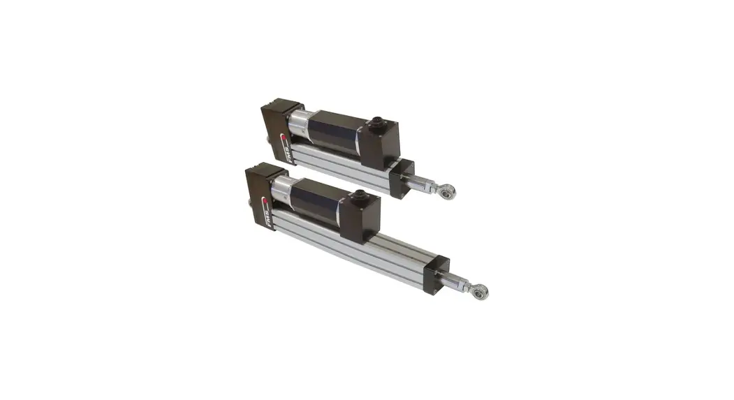
Actuator for unwind and rewind stations
Document Version
08/2017 NS

This operation manual is also available in German. Please contact your local representative.
© by FMS Force Measuring Systems AG, CH-8154 Oberglatt All rights reserved.
Safety Instructions
Description Conditions
a) High danger of health injury or loss of life Danger
This symbol refers to a high risk for persons to get health injury or loss of life. It has to be followed strictly.
b) Risk of damage of machines![]() Caution
Caution
This symbol refers to information, that, if ignored, could cause heavy mechanical
damage. This warning has to be followed absolutely.
c) Note for proper function![]() Note
Note
This symbol refers to important information about proper use. If not followed, malfunction can be the result.
List of Safety Instructions
![]() The winderGLIDE BKS.D.3 may not be stressed over the specification limits either during assembly or operation. In particular, it may not be operated outside the specified temperature range and protection class.
The winderGLIDE BKS.D.3 may not be stressed over the specification limits either during assembly or operation. In particular, it may not be operated outside the specified temperature range and protection class.
![]() The attachment points for the winderGLIDE on the machine must be properly designed
The attachment points for the winderGLIDE on the machine must be properly designed
![]() For correct installation and operation, follow the electrical wiring diagram and instructions in this manual.
For correct installation and operation, follow the electrical wiring diagram and instructions in this manual.
Product Data
Mechanical Dimensions
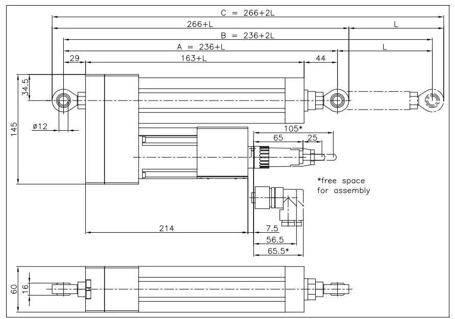
Fig. 1: Outline Drawing
BKS.D.3.0004e
| Dimensions (see Fig. 1) | in mm and [in] |
| Steering offset L | 125 [4.92] or 200 [7.87] |
| Bracket distance A in the center position of toggle link sockets | 236 [9.29] + L |
| Total length B at full travel positions | 236 [9.29] + 2L |
| Total length C | 266 [9.29] + L |
| Screw pitch | 5 [0.2] |
Order Code (Example) winderGLIDE Type D.3

Scope of Delivery
Actuator with spherical rod ends on both sides Not included in the scope of delivery are the preassembled cable and alternative mounting devices. Additional mounting devices like clevis, hinge, or flange for front mounting can be ordered separately.
Installation
Assembly Conditions
The winderGLIDE BKS.D.3 is defined as “partly completed machinery” according to the Directives 2006/42/EC, Article 2. In order to assure the proper functionality of the parts and guarantee the essential health and safety requirements of operators working with it, the following conditions for the assembly of the winderGLIDE must be met:
![]() Caution
Caution
The winderGLIDE BKS.D.3 may not be stressed over the specification limits either during assembly or operation. In particular, it may not be operated outside the specified temperature range and protection class.
![]() Caution
Caution
The attachment points for the winderGLIDE on the machine must be properly designed.
![]() Caution
Caution
For correct installation and operation, follow the electrical wiring diagram and instructions in this manual (ref to Fig. 3 “Pin Assignment”).
Mounting the winderGLIDE Type D.3
There are four mounting devices to assemble the winderGLIDE on the machine frame These mounting devices can be combined according to the table below to meet the requirements of the application (see also Fig.2).
Mounting devices | Joint at the static end | Joint at the moving end |
Spherical rod end |
|
|
Clevis |
|
|
Hinge | – | |
Flange |
| – |

Fig. 2: Mounting Devices of BKS.D.3
BKS.D.3.0005us
The static part of the winderGLIDE must be mounted to the machine frame e.g by means of the spherical rod end on the gearbox or the flange at the end of the spindle housing. The moving rod end is mounted to the winding stand. The BKS.D.3 was designed for horizontal mounting positions.
Installation on unwinding station

Installation on winding station

Pin Assignment

Fig. 3: Wiring diagram winderGLIDE BKS.D.3
Functional Description
The FMS-winderGLIDE D.3 is a dedicated actuator for use in unwinding and rewind stations.
The stepper motor-equipped drive is powerful and simple in its application. The used technology is clean. Especially when used in the food and pharmaceutical packaging industry the FMS-winderGLIDE D.3 has huge advantages compared to hydraulic drives. The FMS-winderGLIDE is designed around an accurate spindle and ball screw which makes the device very precise. The easily accessible connector and its space-saving design make the FMS actuator very suitable for upgrading existing installations.
Technical Specification
| Parameter | Specification |
| Spindle Pitch | 5 |
| Thrust Force [N] | 650 |
| Adjusting Speed [mm/s] | 25 |
| Drive | 16mm spindle, ball screw combination |
| Temperature Range | -10 … 60 °C (14…140 °F) |
| Protection Class | 1P40 |
![]()
| FMS Force Measuring Systems AG Aspstrasse 6 | FMS Italy Via Baranzate 67 | FMS USA, Inc. 2155 Stonington Ave. Suite 119 | FMS UK Highfield, Atch Lench Road |


