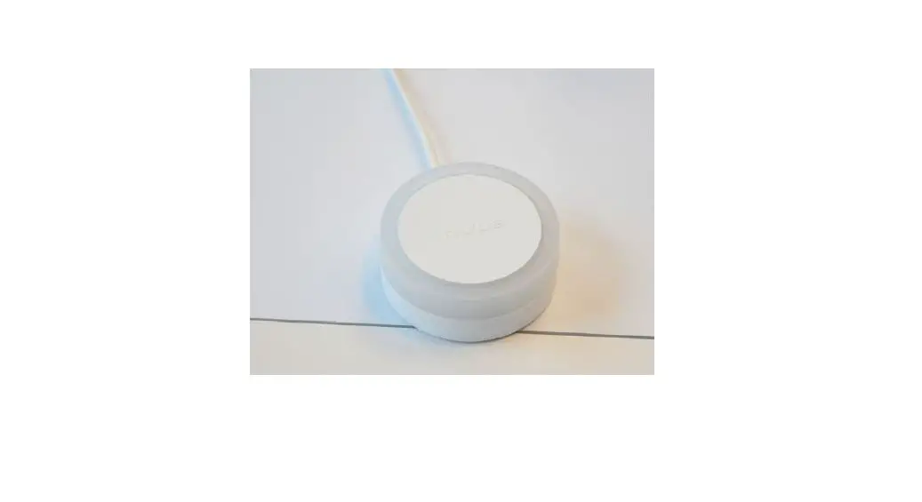
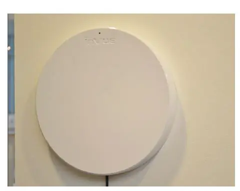
InVue DBD702 Wireless Zone Manager
Wireless Zone Manager DBD702 & Optional LED Emitter DBD703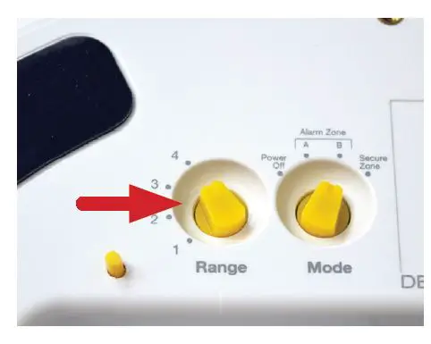
Determine your range settings by consulting the illustration to the right for guidance. Turn the knob to the desired setting by hand or using the key fob tool included with a OneKEY.
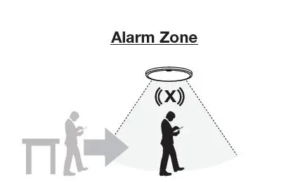
- Alarm starts when sensor enters Alarm Zone. Alarm stops according to chosen mode:
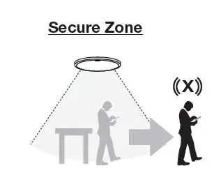
- Alarm starts when sensor leaves Secure Zone.
- Alarm stops when it re-enters Secure Zone or when it times out.
Warning Mode
- Alarm stops when it leaves Alarm Zone.
Continuous Mode
- The alarm continues until it times out.
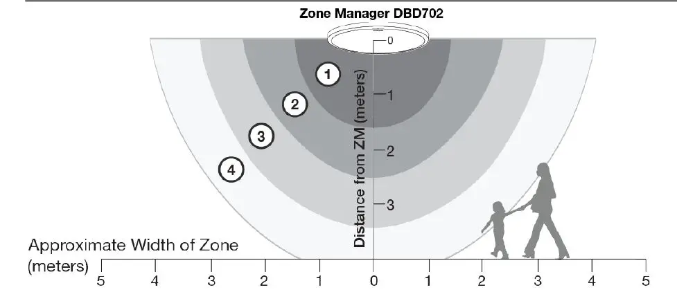
Note: All distances are approximate. The shape and distance of the field can be altered by ferrous objects near the Zone Manager (such as structural steel pillars). The field also extends upwards. Keep these factors in mind when installing and setting the range of the field.
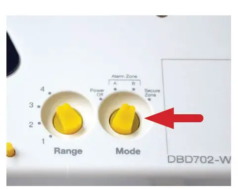
- Consult the following graphics to determine your Mode settings. Turn the knob to the desired setting by hand or using the key fob tool included with a OneKEY.
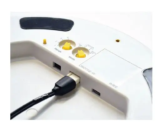
- Plug the power supply into the 2-pin port in the Zone Manager.
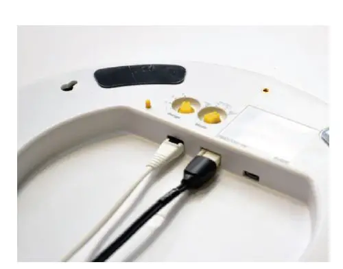
- If installing the optional LED Emitter (DBD703), plug that into the 3-pin port in the Zone Manager
Determine how the Zone Manager
- If using the adhesives, clean the area where the Zone Manager will be mounted.
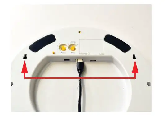
- If mounting to a wall using the 8mm screw holes, the holes are set 8 15/16 inches (225 mm) apart center to center.
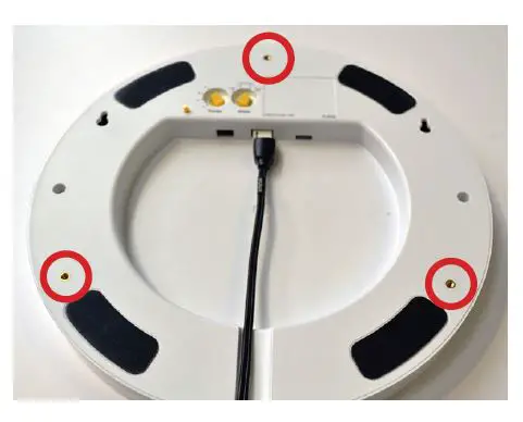
- If threading hardware into the M4 x 0.7 threaded inserts on the Zone Manager to install it suspended or against a horizontal surface (ceiling, underside of a table, etc.), ensure that some type of threadlocker (i.e. Loctite Threadlocker Blue) is used. This will prevent loosening through any vibrations.

- Once it is determined how and where the Zone Manager will be mounted, introduce a sensor and device (following the steps outlined in the sensor instructions) to the alarm zone to test the settings. Adjust the setting as desired.
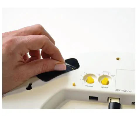
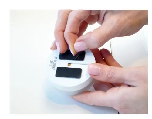
- If mounting with the adhesives, peel the clear film from the 4 adhesives.
- Place the Zone Manager where desired and apply pressure for at least 10 seconds.
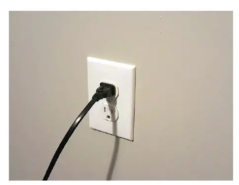
- Connect the power cable to the power supply and plug the power cable into a power outlet.
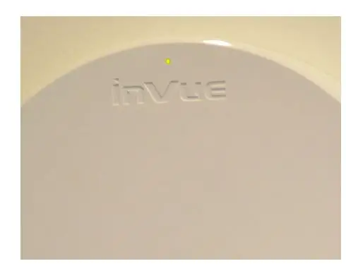
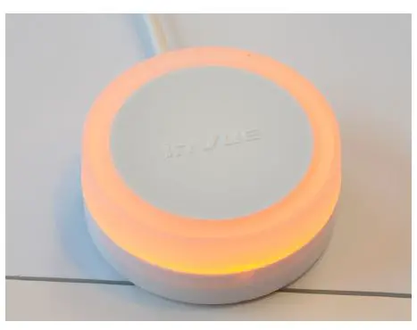
The LED will illuminate gold.
Note: if at any time the LED flashes yellow instead of remaining constant, this indicates that the Zone Manager has lost power is running off of the battery.

- If using the optional LED Emitter, determine where it will be mounted. Ensure that it will be visible. Use the provided alcohol wipe to clean the area where it will be mounted.
- Peel the clear film from the adhesives on the LED Emitter.
 Place the LED Emitter in the predetermined location and apply pressure for at least 10 seconds.
 Place the LED Emitter in the predetermined location and apply pressure for at least 10 seconds.
- The LED Emitter will illuminate.


