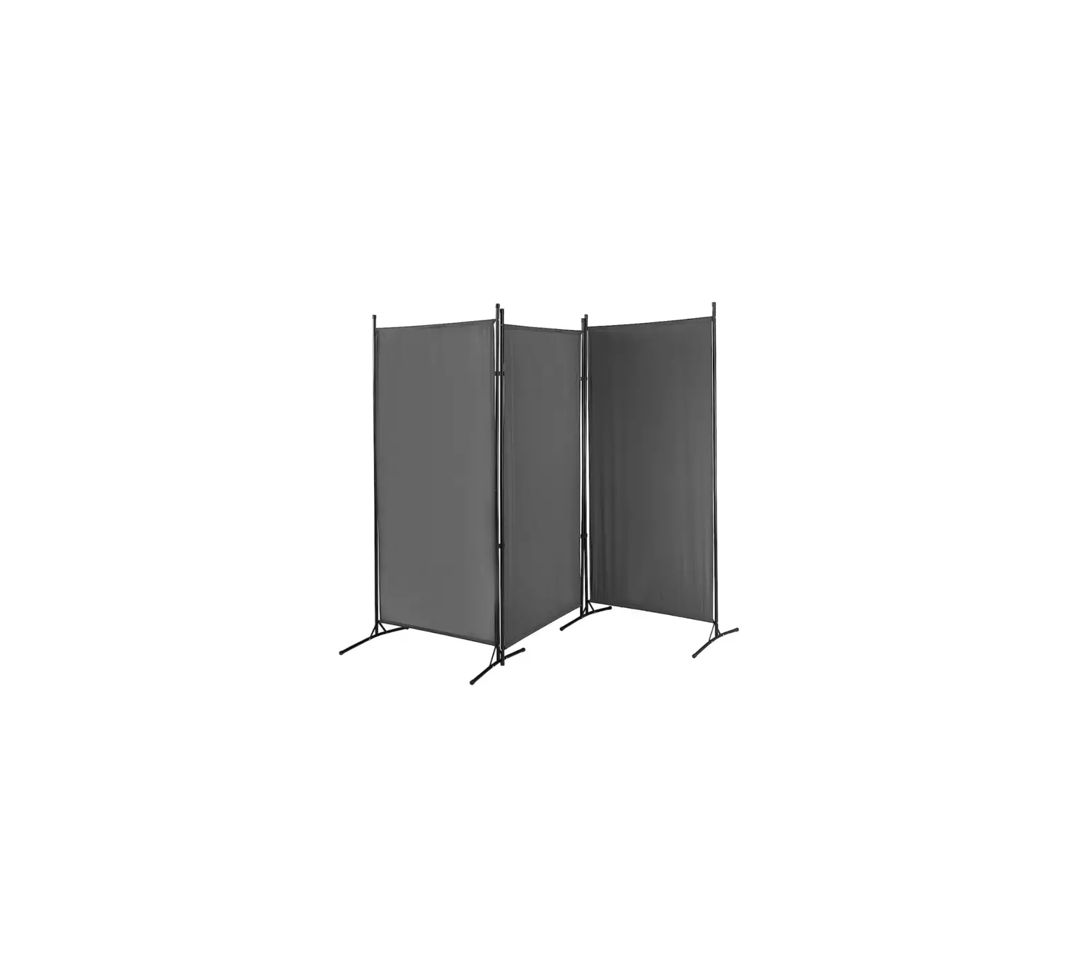
V I V O PP-RD-102B Dark Gray 102×70 Inch Cloth Room Divider
 WARNING!
If you do not understand these directions, or if you have any doubts about the safety of the installation, please call a qualified technician. Check carefully to make sure there are no missing or defective parts. Improper installation may cause damage or serious injury. Do not use this product for any purpose that is not explicitly specified in this manual and do not exceed weight capacity. We cannot be liable for damage or injury caused by improper mounting, incorrect assembly, or inappropriate use.
![]() WARNING: CHOKING HAZARD
WARNING: CHOKING HAZARD
SMALL PARTS – NOT FOR CHILDREN UNDER 3 YEARS. ADULT SUPERVISION IS REQUIRED.
PACKAGE CONTENTS
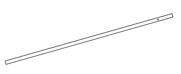
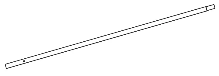
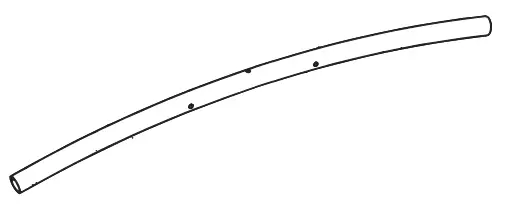
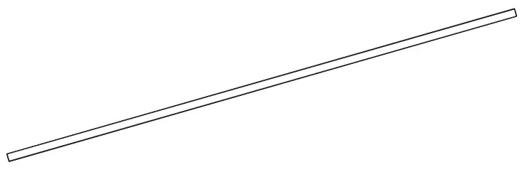
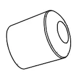
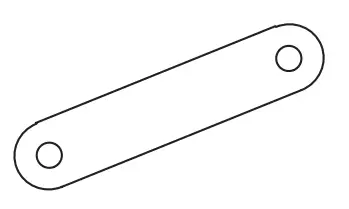
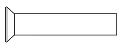
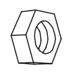
A (x6) | B (x6) | C (x4) | D (x6) |
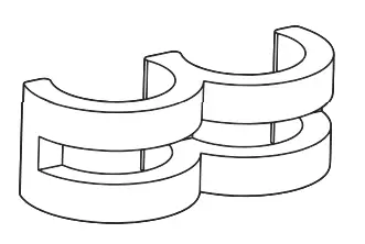
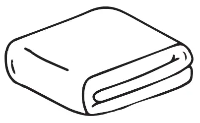
E (x6) | F (x3) | G (x16) | H (x8) |
S-A (x16) | S-B (x8) | S-C (x8) | S-D (x12) |
S-E (x4) | |||

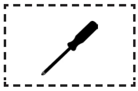
TOOLS NEEDED
- Phillips Screwdriver

ASSEMBLY STEPS
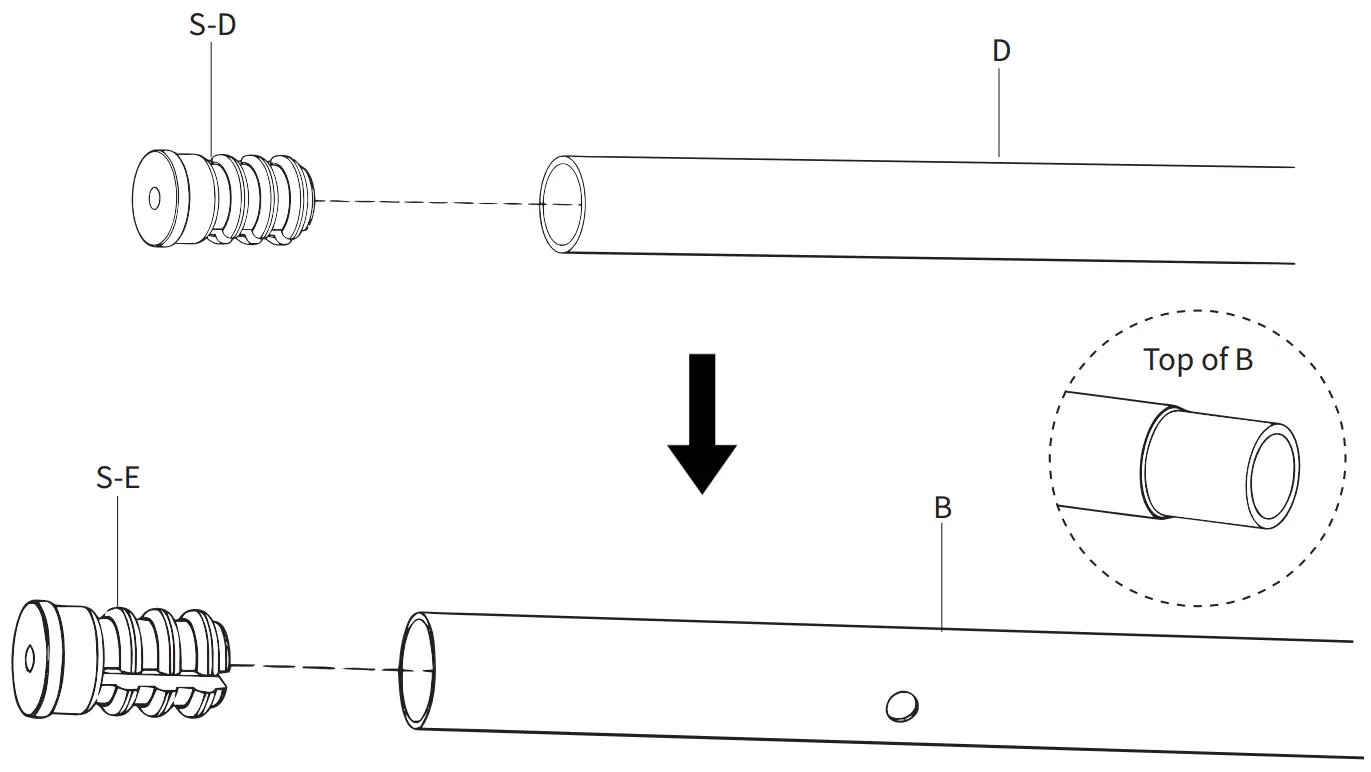
STEP 1
Press Small Inserts (S-D) into both ends of Crossbars (D). Press Large Inserts (S-E) into the bottoms of x4 Lower Vertical Supports (B).
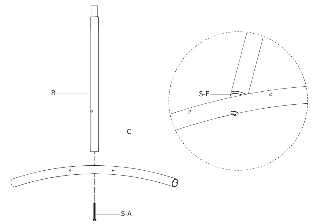
STEP 2
Assemble Feet (C) to Lower Vertical Supports (B) with the installed Large Inserts (S-E) using ST4x40mm Screws (S-A) and a Phillips screwdriver.
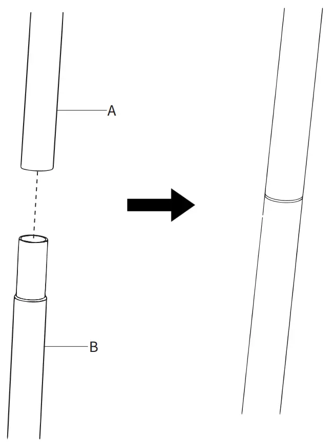
STEP 3
Slide Upper Vertical Supports (A) onto Lower Vertical Supports (B).
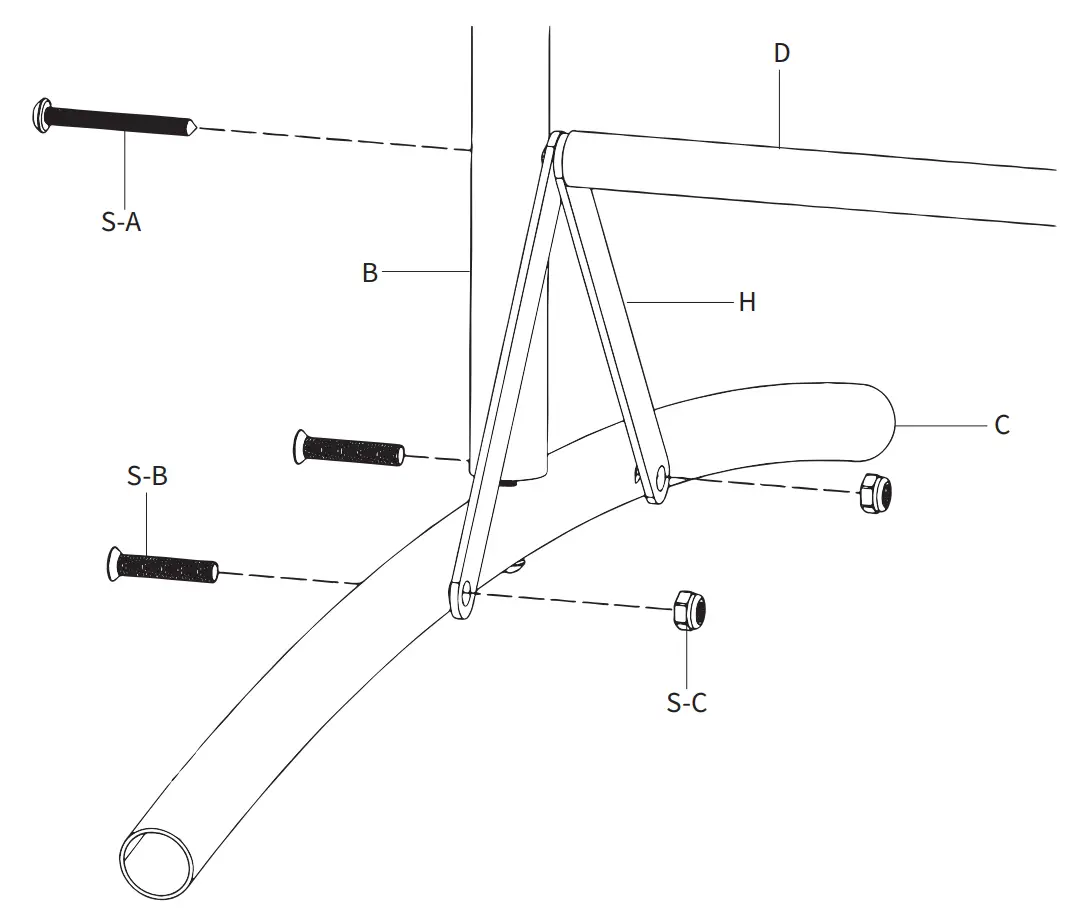
STEP 4
Assemble Braces (H) to Feet (C) using M5x25mm Screws (S-B) and M5 Nuts (S-C). Secure x2 Crossbar (D) to x2 Lower Vertical Supports (B) using ST4x40mm Screw (S-A).
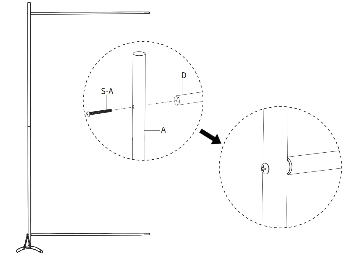
STEP 5
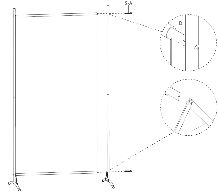
Assemble x2 Crossbars (D) to x2 Vertical Supports (A) using ST4x40mm Screw (S-A) and a Phillips screwdriver.
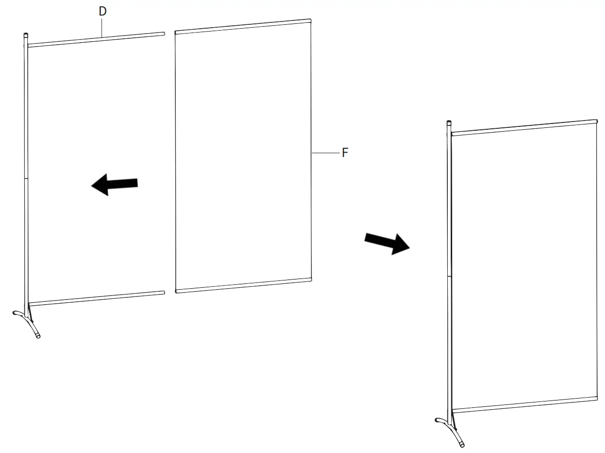
STEP 6
Slide x2 Dividers (F) onto the Crossbars (D).
STEP 7
Secure the other upright assemblies to Crossbars (D) using ST4x40mm Screws (S-A) and a Phillips screwdriver.
STEP 8
Assemble remaining Crossbars (D) and upright assemblies with Divider (F) using ST4x40mm Screws (S-A) and a Phillips screwdriver.

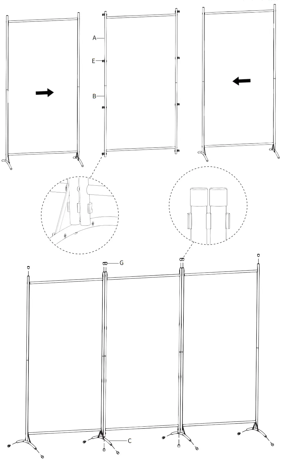
STEP 9
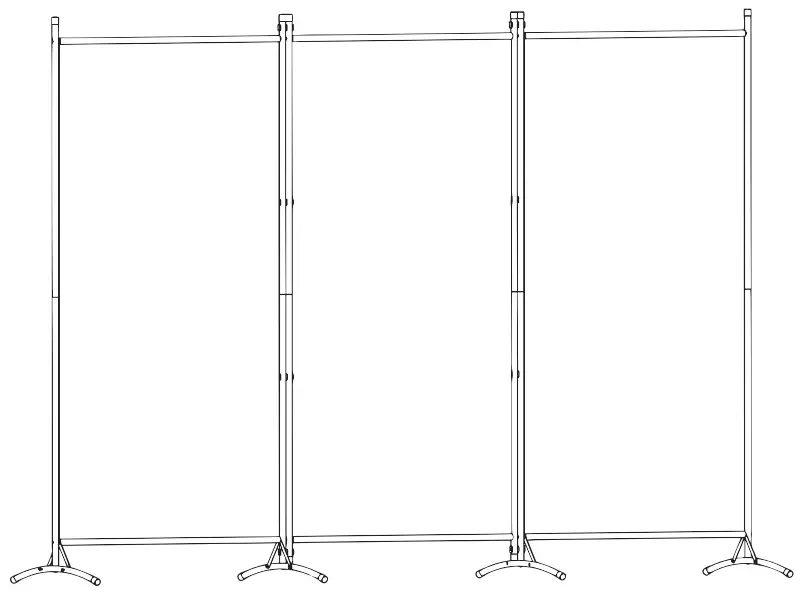
Secure Connector Clips (E) to Upper Vertical Supports (A) and Lower Vertical Supports (B), then assemble the panels together. Assemble End Caps (G) to Upper Vertical Supports (A), x2 Lower Vertical Supports (B)and Feet (C).
SKU: PP-RD-102B
 | Scan the QR code with your mobile device or follow the link for helpful videos and specifications related to this product. https://vivo-us.com/products/pp-rd-102b |
![]() Love your new VIVO setup and want to share?
Love your new VIVO setup and want to share?
Tag us in your photo! @vivo_us
GET IN TOUCH Open Monday – Friday 7:00am – 7:00pm CST,
our dedicated support team can offer immediate assistance with rapid response times. If any parts are received damaged or defective, please contact us. We are happy to replace parts to ensure you have a fully functioning product.
 309-278-5303 309-278-5303 | AVG. RESOLUTION TIME (within office hrs): 5M |
 www.vivo-us.com www.vivo-us.comChat live with an agent! | AVG. RESOLUTION TIME (within office hrs): < 15 M |
AVG. RESPONSE TIME (within office hrs): 1HR 8M
|
FOR MORE VIVO PRODUCTS, CHECK OUT OUR WEBSITE AT: www.vivo-us.com