![]()
Operating Instructions
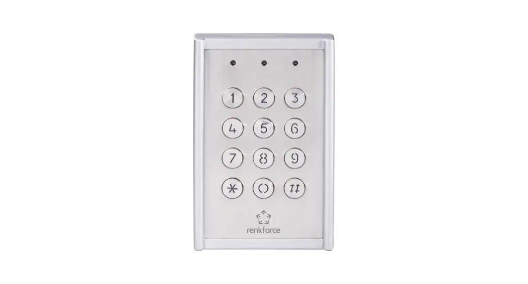
Weatherproof Code Lock IP65
Item No. 751624
Introduction
Dear customer,
Thank you for purchasing this product.
This product complies with the statutory national and European requirements.
To maintain this status and to ensure safe operation, you as the user must observe these operating instructions!
 These operating instructions are part of this product. They contain important notes on commissioning and handling. Also, consider this if you pass on the product to any third party. Therefore, retain these operating instructions for reference!
If there are any technical questions, please contact: www.conrad.com/contact
Explanation of symbols
The symbol with the exclamation mark in the triangle is used to indicate important information in these operating instructions. Always read this information carefully.![]() The arrow symbol indicates special information and advice on operation.
The arrow symbol indicates special information and advice on operation.
Intended use
This code lock is designed to secure doors against unauthorized entry (e.g. office, lobby areas, etc). A maximum of 99 users with different codes can be saved to the unit. It is suitable for connection to electric door openers which have an operating voltage of 12 to 24 V (AC/DC).
In addition, this code lock has an Alarm Outlet (3) (circuit board label: “ALL OUT”; e.g. for connecting a door magnet contact NC) and an Alarm Inlet (5) (circuit board label:
REED; e.g. for connecting a door magnet contact NC).
The code lock is to be operated solely with 12 to 24 V (AC/DC) voltages. The code lock is manufactured to protect category IP65 and is therefore appropriate for unprotected outdoor areas.
For safety and approval purposes, you must not rebuild and/or modify this product. If you use the product for purposes other than those described above, the product may be damaged. In addition, improper use can result in short circuits or other hazards. Read the instructions carefully and store them in a safe place. Make this product available to third parties only together with its operating instructions.
All company names and product names are trademarks of their respective owners. All rights reserved.
Delivery content
- Code lock
- Operating instructions
Up-to-date operating instructions
Download the latest operating instructions at www.conrad.com/downloads or scan the QR code shown. Follow the instructions on the website.
Safety instructions
Read the operating instructions carefully and especially observe the safety information. If you do not follow the safety instructions and information on proper handling in this manual, we assume no liability for any resulting personal injury or damage to property. Such cases will invalidate the warranty/ guarantee.
a) General information
- The device is not a toy. Keep it out of the reach of children and pets.
- Do not leave packaging material lying around carelessly. This may become dangerous playing material for children.
- Protect the device from extreme temperatures, direct sunlight, strong jolts, high humidity, moisture, flammable gases, steam, and solvents.
- Do not place the product under any mechanical stress.
- If it is no longer possible to operate the product safely, take it out of operation and protect it from any accidental use. A safe operation can no longer be guaranteed if the product:
– is visibly damaged,
– is no longer working properly,
– has been stored for extended periods in poor ambient conditions or
– has been subjected to any serious transport-related stresses. - Please handle the product carefully. Jolts, impacts or a fall even from a low height can damage the product.
- Consult an expert when in doubt about the operation, safety, or connection of the device.
- Maintenance, modifications, and repairs must only be completed by a technician or an authorized repair center.
- If you have questions that remain unanswered by these operating instructions, contact our technical support service or other technical personnel.
b) Connected devices
- Also, observe the safety and operating instructions of any other devices which are connected to the product.
Operating and display elements
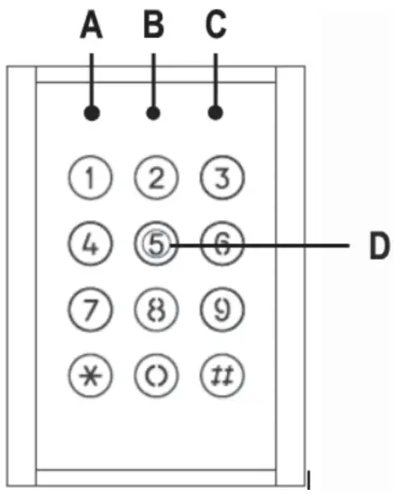
A) red/yellow LED
Is lit red, when the code lock is in operation.
Is lit yellow, when the code lock is in programming mode.
B) Green LED
Is lit green, when the “Lock Out” relay contacts are active.
C) Orange LED
Is lit orange, when the “Aux Out” relay contacts are active.
D) Keypad
For both programming and code entry.
LED and acoustic signaling
| Status | Acoustic alarm sounding | Red/yellow LED (A) | Green LED (B) | Orange LED (C) |
| Initial operation | 3 x signal tone long interval | Lights red | ||
| During operation | Lights red | |||
| Calling up programming mode | 3 x signal tone long interval | Lights yellow | ||
| In Programming mode | Lights yellow | |||
| Correct user password | Lights green | |||
| Door lock reminder (the door is open longer than the timer the setting for the “Lock Out” relay contacts (1) | Flashes | |||
| Correct AUX password | Is lit |
Installation and connection
8.1 InstallationThe code lock is suitable for outdoor use (IP65).
The connection cables must not be kinked or squashed. This can result in malfunctions, short circuits, and defects in the device.
Make sure that cables or wires are not damaged when drilling or bolting in place.
- Detach the housing cover on the back of the code lock by removing the screw on the underside of the housing.
A corresponding tool is supplied with the device. - There are four round markings on the inside of the housing cover. Make the corresponding drill holes using a 3.5-4 mm metal drill bit.
- Another hole for the connection cable (depending on diameter) must be drilled into the center of the housing.
- Attach the code lock with suitable installation material to an even, vertical and vibration-free surface.
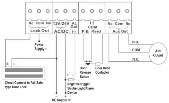
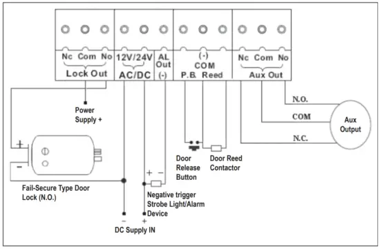
8.2 Connection
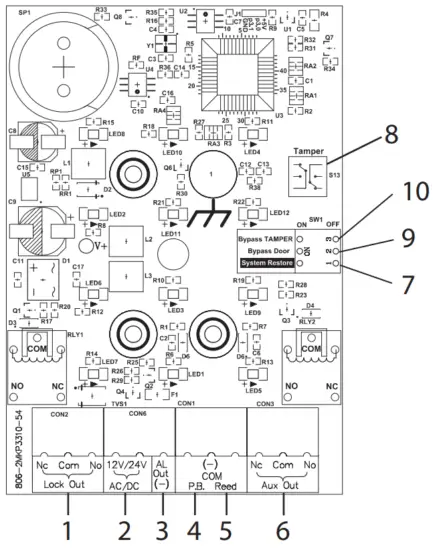
1) “Lock Out” Relay Contacts
2) “12-24 V (AC/DC)” Connection
3) Alarm Outlet (-)
For connecting an alarm siren. (=nega-tive switched; circuit board label = “AL OUT(-)”)
4) “Egress” Connection (P.B.)
An NO sensor can be attached here which can activate the “Lock Out” relay contacts.
5) “Door Magnet Contact” Connection
For connecting a door magnet contact NC). Circuitboard label = REED
6) “Aux Out” Relay Contacts
7) “Reset” Switch
For resetting the lock to factory settings (see chapter “9.8 Restore factory settings (RESET)”).
8) Sabotage Contact
Is triggered as soon as the housing cover is lifted.
9) “Door Magnet Contact” Switch
This switch should switch to OFF as soon as the door magnet contact is connected to the “door
magnet contact connection” (circuit board label = REED).
10) “Bypass Tamper” Switch
This switch bypasses 8) the Sabotage Contact function.
Directly connect to Fail-Safe type Door Lock
Directly connect to Fail-Secure type Door Lock
Programming mode
![]() The master code ex-works is “1234”.
The master code ex-works is “1234”.
To enter the programming mode, enter the Master Code twice in succession.
Example: 1234 1234
As soon as the correct code is entered, the color of the “red/yellow” LED (A) changes from red to yellow.
You are now in programming mode and can make the settings described in the following.
The programming mode can be exited using the “#” button.
9.1 Setting the Master Code
Enter the following key combination in programming mode to assign a new Master Code:![]() 00 MMMM
00 MMMM
MMMM in this case stands for the 4-digit combination of numbers you wish to assign as the Master Code.
9.2 Setting the user password
Enter the following key combination in programming mode to assign a new user password:
Input combination for users 01 to 19:![]() XX UUUU
XX UUUU
Input combination for users 20 to 39:![]() 6 XX UUUU
6 XX UUUU
Input combination for users 41 to 99:![]() 6 XX UUUU
6 XX UUUU
XX in this case stands for the desired user.
UUUU in this case stands for the 4-digit combination of numbers of the desired user password.
9.2.1 Deleting the user password
Enter the following key combination in programming mode to delete a user password:![]() 50 XX
50 XX
XX in this case stands for the user (01 to 99) to be deleted. If all users are to be deleted, enter “00” instead of a number between 01 and 99.
9.3 Setting operating mode
The code lock can be operated in one of two operating modes “Normal-Mode” or “BypassMode”.
In “Normal-Mode” you enter the user password to activate an attached door opener.
In “Bypass-Mode”, once the “Bypass-Code” is entered, the door opener remains activated without an alarm being triggered. Enter the following key combination while in programming mode:![]() 520 Normal-Mode
520 Normal-Mode![]() 521 Bypass-Mode
521 Bypass-Mode
9.3.1 Setting Bypass Code
Enter the following key combination in programming mode to set the bypass code:![]() 54 BBBB
54 BBBB
BBBB in this case stands for the Bypass Code.
9.3.2 Using Bypass Mode![]() The bypass mode can only be used when the bypass mode has been specified in programming mode (combination
The bypass mode can only be used when the bypass mode has been specified in programming mode (combination ![]() 521) and a bypass code has also been assigned.
521) and a bypass code has also been assigned.
Enter the bypass code while in programming mode. This activates the “Lock Out” relay contacts (1).
The “green” LED (B) is lit as a visual confirmation of the setting.
To deactivate the “Lock Out” relay contacts (1) enter the bypass code again. The “green” LED (B) is no longer lit.
9.4 Timer setting for “Lock Out” relay contacts (1)
You can specify the activation time of the “Lock Out” relay contacts (1) (to which an electric door opener may be connected) yourself. Enter the following key combination while in programming mode to do so:![]() 20 TT
20 TT
In this case, TT stands for 01 to 99 seconds. If 00 is set, the relay contacts remain activated until the user password is entered again. On this, see chapter: 9.10 Triggering of “Lock Out” relay contacts (1).
9.5 Keylock
If the automatic key lock is activated, the code lock automatically locks all buttons for 30 seconds after a user password or the Master Code has been entered incorrectly five times (factory setting).
The automatic 30-second lock can be activated/deactivated. Enter the following key combination while in programming mode to do so:![]() 51
51
You can also specify after which errors the key lock should be activated. Enter the following key combination while in programming mode to do so:![]() 53 0 after the input of 20 incorrect digits in sequence
53 0 after the input of 20 incorrect digits in sequence![]() 53 1 after five incorrect user passwords or Master Code inputs
53 1 after five incorrect user passwords or Master Code inputs
9.6 Setting password for “Aux Out” relay contacts (6)![]() The factory setting is no password for “Aux Out” relay contacts (6).
The factory setting is no password for “Aux Out” relay contacts (6).
Enter the following key combination in programming mode to assign a new password:![]() 40 HHHH
40 HHHH
HHHH in this case stands for the 4-digit combination of numbers you wish to assign as the desired password.
9.6.1 Setting activation period for “Aux Out” relay contacts (6)
You can specify the activation time of the “Aux Out” relay contacts (i) (to which a door gong may be connected) yourself. Enter the following key combination while in programming mode to do so:
![]() 58 TTT
58 TTT
TTT in this case stands for 001 to 999 seconds. If 000 is set, the relay contacts remain activated until the user password for the “Aux Out” relay contacts is entered again (=Toggle Mode).
9.6.2 Setting activation mode for “Aux Out” relay contacts (6)
The factory setting is for the “Aux Out” relay contacts (6) to be activated by the password for the “Aux Out” relay contacts (6).
You can however activate the relay contacts in different ways. For this purpose, this code lock offers you convenient options to specify an activation mode.
Enter the following key combination in programming mode to assign the desired activation mode:
![]() 57 C
57 C
C in this case stands for the desired mode type.
Mode types:
C = 0 No function
C = 1 allows door monitoring (*)
C = 2 allows the triggering of the “Aux Out” relay contacts in the case of incorrect entry of a user password or the Master Code
C = 3 allows the triggering of the “Aux Out” relay contacts via the “![]() ” button.
” button.
C = 4 allows the triggering of the “Aux Out” relay contacts via the sabotage contact.
C = 5 allows extended door monitoring (**)
C = 6 allows the triggering of the “Aux Out” relay contacts as soon as the “Lock Out” relay contacts are activated.
C = 7 allows the triggering of the “Aux Out” relay contacts via the assigned password.
(*) monitoring
Behavioral mode: At the entry of the user password triggers the “Lock Out” relay contacts (1).
If the magnet contact is opened the “Aux Out” relay contacts (6) are triggered. If the sensor attached to the “Egress” outlet (4) is activated, this triggers the “Lock Out” relay contacts (1).
(**) extended door monitoring
Behavioral mode: At the entry of the user password this triggers the “Lock Out” (1) and “Aux Out” (6) relay contacts. The “green” LED (B) flashes when the magnet contact is open. If the sensor attached to the “Egress” outlet (4) is activated, this triggers the “Lock Out” and “Aux Out” (6) relay contacts.
9.7 Timer setting for “Alarm Outlet” (3)
You can specify the trigger time of the “Alarm Outlet” (3) (to which a siren may be connected) yourself. Enter the following key combination while in programming mode to do so:![]() 56 TTT
56 TTT
TTT in this case stands for 001 to 999 seconds.
9.7.1 Activation mode for “Alarm Outlet” (3)
You can however activate the alarm outlet in different ways. For this purpose, this code lock offers you convenient options to specify an activation mode.
Enter the following key combination in programming mode to assign the desired activation mode:![]() 55 C
55 C
C in this case stands for the desired mode type.
Mode types:
C = 0 No function
C = 1 allows the triggering of the alarm outlet in connection with the extended door monitoring (see chapter: “9.6.2 Setting activation mode for “Aux Out” relay contacts(6)”.
C = 2 allows the triggering of the alarm outlet via the sabotage contact.
C = 3 allows mode types 1 and 2 together
9.8 Restore factory settings (RESET)
Proceed in the following sequence:
1) Remove your code lock from the power supply.
2) Move the Switch “Reset” (7) to the ON position.
3) Reconnect the operating voltage again.
4) The internal signaller is now active.
5) Move the Switch “Reset” (7) to the OFF position.
9.9 Brief overview of input combinations and factory settings
| Function | Input Combination (while you are in programming mode) | Factory setting |
| Master code | 1234 | |
| User password | 01 = 3333 | |
| Timer setting of the “Lock Out– relay contacts | 05 seconds | |
| AUX password | Must be programmed | |
| Deleting the user password | ||
| Key lock | deactivated | |
| Operational mode | 0 = Normal mode | |
| Erroneous input > Activation | 0 = after the input of 20 incorrect digits in sequence | |
| Bypass code | Must be programmed | |
| Activation mode alarm outlet | 3 = allows mode types 1 and 2 together | |
| Timer setting alarm outlet | 030 seconds | |
| Activation mode Aux Out | 7 = allows the triggering of the “Aux Out” relay contacts via the assigned password. | |
| Timer setting Aux Out | 000 = Toggle mode | |
| Additional users | empty | |
| Additional users | empty |
9.10 Triggering of “Lock Out” relay contacts (1)
Enter the following key combination when you are not in programming mode to trigger the “Lock Out” relay contacts.
![]() UU XXXX XXXX
UU XXXX XXXX
UU in this case stands for the user (01 to 99).
XXXX stands for the corresponding user password.
You can also trigger the “Lock Out” relay contacts (1) by activating the “Egress” sensor.
In addition, the relay contacts can also be activated by the bypass mode. See also the chapters: “9.3 Setting operating mode, 9.3.1 Setting Bypass Code, and 9.3.2 Using Bypass Mode”.
Care and cleaning
![]() Do not use any aggressive cleaning agents, rubbing alcohol, or other chemical solutions as they can cause damage to the housing and malfunction.
Do not use any aggressive cleaning agents, rubbing alcohol, or other chemical solutions as they can cause damage to the housing and malfunction.
- The product does not require maintenance.
- Clean the product with a dry, fiber-free cloth.
- For more stubborn dirt, you can moisten the cloth slightly with lukewarm water.
Declaration of Conformity (DOC)
Conrad Electronic SE, Klaus-Conrad-Straße 1, D-92240 Hirschau hereby declares that this product conforms to the 2014/53/EU directive.
Click on the following link to read the full text of the EU declaration of conformity:
www.conrad.com/downloads
Enter the product item number in the search box. You can then download the EU declaration of conformity in the available languages.
Disposal
![]() Electronic devices are recyclable waste and must not be disposed of in the household waste. At the end of its service life, dispose of the product in accordance with applicable regulatory guidelines.
Electronic devices are recyclable waste and must not be disposed of in the household waste. At the end of its service life, dispose of the product in accordance with applicable regulatory guidelines.
Remove any inserted (rechargeable) batteries and dispose of them separately from the product.
Technical data
Input voltage ……………………………..12 – 24 V AC/DC
Lock Out Relay Contact ………………max. 3 A
Aux Out Relay Contact ……………….max. 3 A
Alarm Outlet ………………………………12 V/DC, 500 mA (negative outlet) (-)
Type of protection ………………………IP65
Dimensions (W x H x D) ……………..approx. 80 x 120 x 36 mm
Weight ……………………………………..approx. 530 g
This is a publication by Conrad Electronic SE, Klaus-Conrad-Str. 1, D-92240 Hirschau (www.conrad.com).
All rights including translation reserved. Reproduction by any method, e.g. photocopy, microfilming, or the capture in electronic data processing systems requires prior written approval by the editor. Reprinting, also in part, is prohibited. This publication represents the technical status at the time of printing. Copyright 2021 by Conrad Electronic SE.
References
 France.fr : Actualités, destinations et infos du tourisme en France
 Conrad Electronic » Your sourcing platform
-
Conrad Electronic – Alle Teile des Erfolgs
-
Conrad Electronic » Your Sourcing Platform
-
Contact Us | Conrad.com
-
Document
-
Conrad Electronic Online Shop » Alle Teile des Erfolgs
-
Conrad Electronic » Your Sourcing Platform


