
Philio Tech
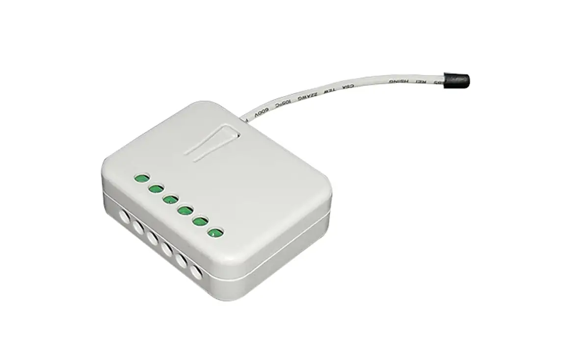
Relay Insert 2 * 1.5 KW
SKU: PHI_PAN06

Quickstart
This is a
On/Off Power Switch
for
Europe.
To run this device please connect it to your mains power supply.
Tripple Click the Button on the device confirms the inclusion, exclusion and association. After power up it will stay in auto inclusion mode for 4 minutes. To support handling of the device when already installed the external switch can be used for inclusion or exclusion for 3 minutes after power up.
Important safety information
Please read this manual carefully. Failure to follow the recommendations in this manual may be dangerous or may violate the law.
The manufacturer, importer, distributor and seller shall not be liable for any loss or damage resulting from failure to comply with the instructions in this manual or any other material.
Use this equipment only for its intended purpose. Follow the disposal instructions.
Do not dispose of electronic equipment or batteries in a fire or near open heat sources.
What is Z-Wave?
Z-Wave is the international wireless protocol for communication in the Smart Home. This
device is suited for use in the region mentioned in the Quickstart section.

Z-Wave ensures a reliable communication by reconfirming every message (two-way
communication) and every mains powered node can act as a repeater for other nodes
(meshed network) in case the receiver is not in direct wireless range of the
transmitter.
This device and every other certified Z-Wave device can be used together with any other
certified Z-Wave device regardless of brand and origin as long as both are suited for the
same frequency range.
If a device supports secure communication it will communicate with other devices
secure as long as this device provides the same or a higher level of security.
Otherwise it will automatically turn into a lower level of security to maintain
backward compatibility.
For more information about Z-Wave technology, devices, white papers etc. please refer
to www.z-wave.info.
Product Description
This Insert Switch allows controlling two independent loads both wirelessly via Z-Wave and locally utilizing a traditional wall switch. Thanks to its calibration technology the device cannot only be used to switch resistive devices but also works perfectly with many kind of reactive or resistive loads such as fluorescent lights or LEDs. The device is placed in a wall box right behind the normal switch. The switch is not longer directly connected to the load but acts as input device for the insert that is controlling the load. This device is designed for a 3 wire system and needs a neutral wire in the wall box.
Prepare for Installation / Reset
Please read the user manual before installing the product.
In order to include (add) a Z-Wave device to a network it must be in factory default
state. Please make sure to reset the device into factory default. You can do this by
performing an Exclusion operation as described below in the manual. Every Z-Wave
controller is able to perform this operation however it is recommended to use the primary
controller of the previous network to make sure the very device is excluded properly
from this network.
Reset to factory default
This device also allows to be reset without any involvement of a Z-Wave controller. This
procedure should only be used when the primary controller is inoperable.
Tripple Click the button on the device to enter inclusion mode. Within 1 second press the button again for 5 seconds until LED is off.
Safety Warning for Mains Powered Devices
ATTENTION: only authorized technicians under consideration of the country-specific
installation guidelines/norms may do works with mains power. Prior to the assembly of
the product, the voltage network has to be switched off and ensured against re-switching.
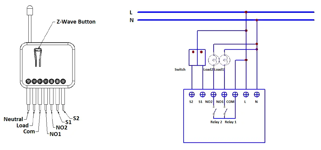
Installation
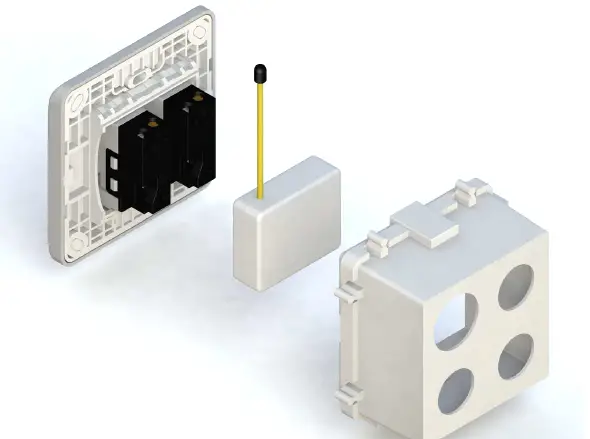
Put the in wall switch into a wall box and connect the pins as shown in the figure.
Inclusion/Exclusion
On factory default the device does not belong to any Z-Wave network. The device needs
to be added to an existing wireless network to communicate with the devices of this network.
This process is called Inclusion.
Devices can also be removed from a network. This process is called Exclusion.
Both processes are initiated by the primary controller of the Z-Wave network. This
controller is turned into exclusion respective inclusion mode. Inclusion and Exclusion is
then performed doing a special manual action right on the device.
Inclusion
Tripple Click the button on the device confirms inclusion. After power up it will stay in auto inclusion mode for 4 minutes. To support handling of the device when already installed the external switch can be used for inclusion or exclusion for 3 minutes after power up.
Exclusion
Tripple Click the button on the device confirms exclusion.”
Product Usage
Manual Operation
The device can be operated using the externally connected switch. Three different modes are supported:
- Edge Mode: Die Position of the external switch determines the switching state of the relay. After a wireless switching command it may be needed to operate the switch twice to return to the direct relation of switch position and relay state. This mode is the factory default mode.
- Toogle Mode: Each “ON”-Position of the external switch will toggle the state of the relays. This mode is particularly suited for mono-stable switches.
- Edge/Toggle-Mode: Every change of the state of the external switch results in a change of the relay state.
Remote Operation
Remote On/Off control of the switch is possible with any Z-Wave controller. Further you can set associations to let your device controlled by other Z-Wave devices like sensors.
Node Information Frame
The Node Information Frame (NIF) is the business card of a Z-Wave device. It contains
information about the device type and the technical capabilities. The inclusion and
exclusion of the device is confirmed by sending out a Node Information Frame.
Beside this it may be needed for certain network operations to send out a Node
Information Frame. To issue a NIF execute the following action:
Tripple Click the button on the device sends out a Node Information Frame.
Quick trouble shooting
Here are a few hints for network installation if things dont work as expected.
- Make sure a device is in factory reset state before including. In doubt exclude before include.
- If inclusion still fails, check if both devices use the same frequency.
- Remove all dead devices from associations. Otherwise you will see severe delays.
- Never use sleeping battery devices without a central controller.
- Dont poll FLIRS devices.
- Make sure to have enough mains powered device to benefit from the meshing
Association – one device controls an other device
Z-Wave devices control other Z-Wave devices. The relationship between one device
controlling another device is called association. In order to control a different
device, the controlling device needs to maintain a list of devices that will receive
controlling commands. These lists are called association groups and they are always
related to certain events (e.g. button pressed, sensor triggers, …). In case
the event happens all devices stored in the respective association group will
receive the same wireless command wireless command, typically a ‘Basic Set’ Command.
Association Groups:
Group NumberMaximum NodesDescription
| 1 | 1 | The Switch will report ON/OFF status of Relay1 and Relay2 |
| 2 | 1 | The Switch will report ON/OFF status of Relay1 |
| 3 | 1 | The Switch will report ON/OFF status of Relay2 |
Configuration Parameters
Z-Wave products are supposed to work out of the box after inclusion, however
certain configuration can adapt the function better to user needs or unlock further
enhanced features.
IMPORTANT: Controllers may only allow configuring
signed values. In order to set values in the range 128 … 255 the value sent in
the application shall be the desired value minus 256. For example: To set a
parameter to 200 it may be needed to set a value of 200 minus 256 = minus 56.
In case of a two byte value the same logic applies: Values greater than 32768 may
needed to be given as negative values too.
Parameter 1: Slected Relay
If Controller not using Multi_Channel command class to access the relay of” PAN06, you may configure the select value to react the Basic Command Class or” Binary Switch Command Class.
Size: 1 Byte, Default Value: 3
SettingDescription
| 1 | Relay 1 |
| 2 | Relay 2 |
| 3 | Relay 1 und Relay 2 |
Parameter 2: Edge or Pulse mode or Edge-Toggle mode
Manual switch S1 and S2 can set to Edge mode or Pulse mode or Edge-Toggle mode.
Size: 1 Byte, Default Value: 1
SettingDescription
| 1 | Edge Mode |
| 2 | Pulse Mode |
| 3 | Edge/Toggle Mode |
Parameter 3: Restore switch state mode
Whenever the AC power return from lost, PAN06 will restore the switch state which” could be SWITCH OFFã€LAST SWITCH STATEã€SWITCH ON.
Size: 1 Byte, Default Value: 1
SettingDescription
| 0 | Switch off |
| 1 | Last switch state |
| 2 | Switch on |
Parameter 4: Auto off timer
Whenever PAN06 switches to on, the auto off timer begin to count down. After the” timer decrease to zero, it will switch to off automatically. However if Auto off timer” is set as 0, the auto off function will be disabled.
Size: 2 Byte, Default Value: 0
SettingDescription
| 0 | Disable |
| 1 – 32767 | Seconds |
Parameter 5: RF off command mode
Whenever a switch off command, BASIC_SET, BINARY_SWITCH_SET,” SWITCH_ALL_OFF, is received, it could be interpreted as 4 variety of commands.
Size: 1 Byte, Default Value: 0
SettingDescription
| 0 | Switch off |
| 1 | ignore |
| 2 | Switch toggle |
| 3 | Switch on |
Parameter 6: Existence of Endpoint3
The endpoint3 of Multi-Channel Command Class is related to relay1 and relay2.” It may be redundant for the need to control relay1 or relay2 individually. When the” Existence of Endpoint3 is set as 0, the endpoint3 of Multi-Channel Command Class” will be disabled.
Size: 1 Byte, Default Value: 1
SettingDescription
| 1 | Endpoint3 exist |
| 2 | No Endpoint3 |
Technical Data
| Dimensions | 0.0470000×0.0390000×0.0160000 mm |
| Weight | 40 gr |
| Hardware Platform | SD3502 |
| EAN | 4713698571160 |
| IP Class | IP 20 |
| Voltage | 230 Der Endpunkt3 der Mehrkanal-Befehlsklasse bezieht sich auf Relais1 und Relais2. Es kann überflüssig sein, die Notwendigkeit, Relais1 oder Relais2 einzeln zu steuern. Wenn die Existenz von Endpunkt3 als 0 gesetzt ist, wird der Endpunkt3 der Mehrkanal-Befehlsklasse deaktiviert. |
| Load | 2x 1500W |
| Device Type | On/Off Power Switch |
| Generic Device Class | Binary Switch |
| Specific Device Class | Binary Power Switch |
| Firmware Version | 01.08 |
| Z-Wave Version | 03.5f |
| Certification ID | ZC10-14120009 |
| Z-Wave Product Id | 0x013c.0x0001.0x0013 |
| Frequency | Europe – 868,4 Mhz |
| Maximum transmission power | 5 mW |
Supported Command Classes
- Basic
- Switch Binary
- Switch All
- Scene Activation
- Scene Actuator Conf
- Association Grp Info
- Device Reset Locally
- Zwaveplus Info
- Multi Channel
- Configuration
- Alarm
- Manufacturer Specific
- Powerlevel
- Protection
- Firmware Update Md
- Association
- Version
Explanation of Z-Wave specific terms
- Controller — is a Z-Wave device with capabilities to manage the network.
Controllers are typically Gateways,Remote Controls or battery operated wall controllers. - Slave — is a Z-Wave device without capabilities to manage the network.
Slaves can be sensors, actuators and even remote controls. - Primary Controller — is the central organizer of the network. It must be
a controller. There can be only one primary controller in a Z-Wave network. - Inclusion — is the process of adding new Z-Wave devices into a network.
- Exclusion — is the process of removing Z-Wave devices from the network.
- Association — is a control relationship between a controlling device and
a controlled device. - Wakeup Notification — is a special wireless message issued by a Z-Wave
device to announces that is able to communicate. - Node Information Frame — is a special wireless message issued by a
Z-Wave device to announce its capabilities and functions.


 Switch Module Pan05-1b Manual")