Puretec WTV4400 E1 and E3 Automatic Control Valve Service Kit
Puretec Customer Service
Thank you for purchasing a Puretec E1 & E3 Automatic Control Valve Service Kit. This user guide contains instructions on how to perform preventative maintenance or repairs on a Puretec E1 or E3 Control Valves. Puretec E1 & E3 control valves can be found on:
- SOL Series Automatic Water Softeners
- IRS & IRX Series Iron Removal Systems
- CFS Series Carbon Filters
- SFS Series backwashing Sediment Filters
Be careful to ensure the information and illustration is applicable to your particular unit.Call the Puretec Customer Care Team on 1300 140 140 (AU) and 0800 130 140 (NZ) for more details.
Introduction
The included spacer stack and piston(s) are key components in redirecting water within the valve. Although faults are rare, the following faults are indications that the spacer stack may need replacing:
- Water is continuously leaking from the backwash drain line
- Unfiltered water is coming from the outlet
- Error codes 1002 or 1003
- Not using any salt
- The brine tank is overflowing
- Salt water being delivered during service
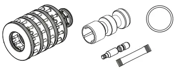
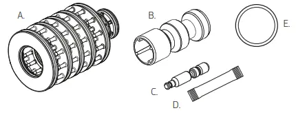
Kit Inclusions
Unpack the kit. Ensure all parts are present and have not been damaged in transport. You should have:
- (A) Spacer Stack Assembly
- (B) Main Piston
- (C) Brine Piston (only used for SOL series valves)
- (D) Food Grade Silicone Lubricant
- (E) BA-CR2032 Battery

Video Servicing Instructions
Scan the QR code for instant access to our training video with step by step instructions.

Fig. 1 – E1 Front Cover and Drive Assembly
| No. | Part Code | Description |
| 1 | WTV5121 | Front Cover, Suits E1 Valve |
| 2 | WTV5690 | Motor |
| 3 | WTV5800 | Drive Bracket |
| 4 | WTV5720 | PCB, Suits E1 Valve |
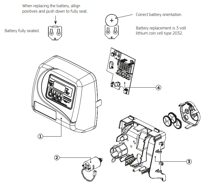
Fig. 2 – E3 Front Cover and Drive Assembly
| No. | Part Code | Description |
| 1 | WTV5123 | Front Cover, Suits E3 Valve |
| 2 | WTV5690 | Motor |
| 3 | WTV5800 | Drive Bracket |
| 4 | WTV5730 | PCB, Suits E3 Valve |
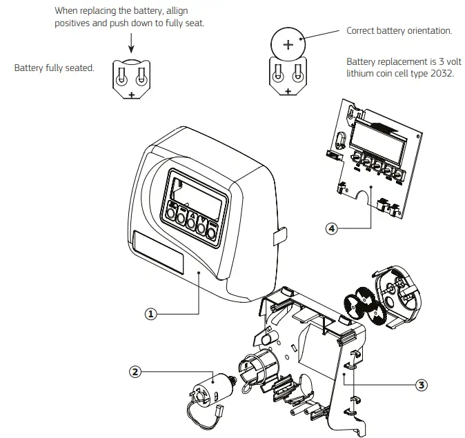
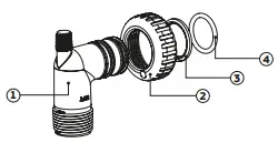
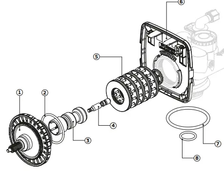
Fig. 3 – Drive Cap Assembly, Pistons and Spacer Stack Assembly
| No. | Part Code | Description |
| 1 | WTV5510 | Drive Cap Assembly |
| 2 | O-ring, 228 | |
| 3 | WTV5650 | Downflow Piston Assembly |
| 4 | WTV6020 | Regenerant Piston |
| 5 | WTV5520 | Spacer Stack Assembly |
| 6 | WTV5540 | Drive Back Plate |
| 7 | WTV6090 | Main O-ring, 337 |
| 8 | WTV6100 | O-ring, 215 |
Spacer Stack & Piston
- Isolate the water supply and release the pressure by opening an outlet after the system.
 NOTE: If you have the optional bypass assembly, turn the handles so that they point toward each other.
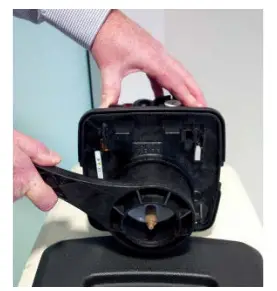
 - Remove the weather cover.On a cabinet-style system,reach around the back of the unit and pull the 2 sides of the cover away from the pipe connection and lift.

- For the almond cover, squeeze both sides and lift to release.

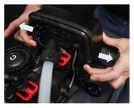
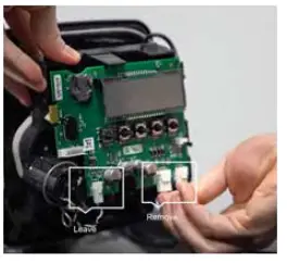
- Remove the display front cover by pulling the tabs located on either side by pulling them away from the valve body.

- Disconnect the power supply, and the flow meter or DP switch cables if present. The motor connection on the bottom left can remain connected.

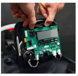
- Remove the Drive bracket by lifting the 2 tabs at the top of the bracket.

- Remove the drive cap assembly. To remove the drive cap assembly, if you have the Puretec WTV5180 spanner and multi-tool, use the
tool to turn the slotted drive cap assembly anti-clockwise. Alternatively, if you don’t have the spanner, use a flat-headed screwdriver by inserting it through the slots around the top of the
drive cap assembly and into the notches moulded into the drive back plate. The notches are visible through the holes. Lever
the screwdriver so the drive cap assembly turns counterclockwise.
- Remove Piston(s) Once the drive cap is removed, you can see the orange piston. The black brine piston is found on the softeners
only.
To remove the black brine piston, slide sideways to unsnap it from its latch taking care that it is pressed in the direction of the latch
opening.
To remove the main piston(s), turn the white gear anti-clockwise so that the orange piston is fully extended. This will allow the piston
to be removed from the spindle and replaced. Unsnap the main piston from its latch by pressing on the side of the piston with the number.
- Next, remove the grey spacer stack assembly and replace it. The spacer stack has external and internal O- rings for redirecting the water during regeneration or backwash. The internal O-rings are the most common point of damage. The internal O-rings have a custom profile so are not individually replaceable. To remove the spacer stack, simply pull it out with a thumb and forefinger.
- To reassemble, insert the new spacer stack. If required, use the supplied silicone grease to lubricate the O- rings and piston.
- Insert the drive cap and piston(s) into the spacer stack and valve body then tighten, taking care to screw it all the way in without over tightening. If you have a softener, make sure the black brine piston is secure before inserting it into the spacer stack.
- Insert the drive bracket into the bottom locators, and click back into position. If it doesn’t snap in easily, check that the wiring is out of the way.
- Re-attach the cables and front display cover.

 NOTE: If you have the optional bypass assembly, turn the handles so that they point toward each other.
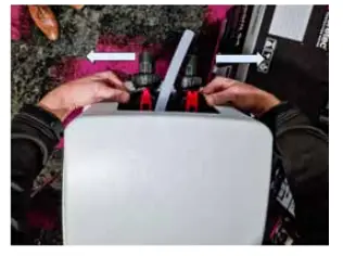

 Alternatively, if you don’t have the spanner, use a flat-headed screwdriver by inserting it through the slots around the top of the
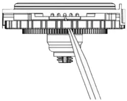
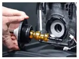

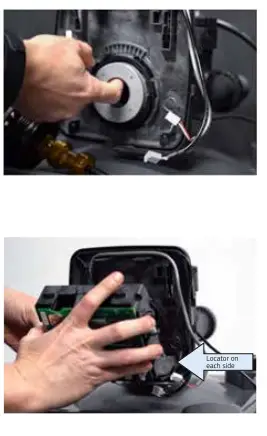
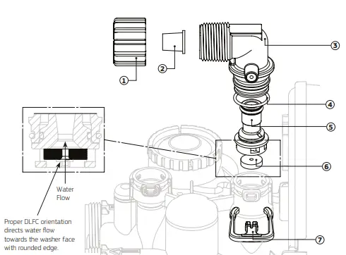
Fig. 4 – 1″ Drain Line
| No. | Part Code | Description |
| 1 |
WTV5080 | 1″ Drain Line Assembly Body |
| 2 | O-ring, 019 | |
| 3 | Split Ring | |
| 4 | 1″ Quick Connect Nut | |
| 5 | 1″ Drain FTG Adaptor | |
| 6 | O-ring, 215 | |
| 7 | WTV5410 | Elbow Locking Clip |
| 8 | WTV5340 | Drain Line Flow Connector (DLFC) 42 Lpm |
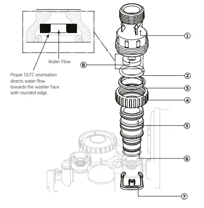
Fig. 5 – ¾” Drain Line Elbow
| No. | Part Code | Description |
| 1 | WTV5160 | ¾” Nut |
| 2 | WTV5170 | ⅝” Tube Insert |
| 3 | WTV5940 | ¾” Drain Line Elbow, Male |
| 4 | – | O-ring, 019 |
| 5 | – | DLFC Retainer Assembly |
|
6 | WTV5190 | Drain Line Flow Connector (DLFC) 2.6 Lpm, suits SOL30 |
| WTV5240 | Drain Line Flow Connector (DVFC) 10.2 Lpm, suits SOL40 | |
| WTV5290 | Drain Line Flow Connector (DLFC) 28.4 Lpm, suits SOL45 / SOL60 | |
| 7 | WTV5410 | Elbow Locking Clip |
| 3, 4 & 5 | WTV5930 | ¾” Drain Line Elbow with DLFC Retainer |
Flow Control Servicing
- Isolate the water supply and release the pressure by opening an outlet after the system. If you have the optional bypass assembly, turn the handles so that they point toward each other.
- On top of the control valve, remove the red clip closest to the front of the unit and remove the fitting. This is the drain line flow controller. Inspect the rubber ring and ensure it is free of any obstructions.

- [Softener only] On top of the control valve, remove the red clip closest to the back of the unit and remove the fitting. This is the brine line flow controller. Inspect the rubber ring and ensure it is free of any obstructions.

- Reassemble ensuring the fitting is fully inserted and locked in with the red clip(s)
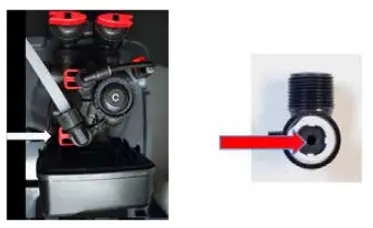
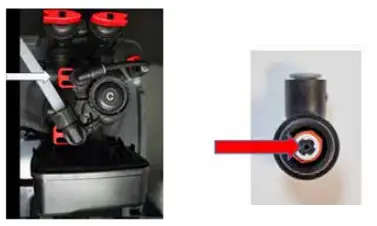
Fig. 6 – ⅜” Brine Line Elbow and Refill Port Plug
| No. | Part Code | Description |
| 1 | WTV5430 | ⅜” Tube Insert |
| 2 | WTV5440 | ⅜” Nut |
| 3 | WTV5400 | ⅜” Brine Elbow, Male |
| 4 | WTV6180 | Refill Port Plug |
| 5 | – | O-ring, 019 |
| 6 | – | RFC Retainer Assembly |
| 7 | WTV5410 | Elbow Locking Clip |
| 1,2,3,5 & 6 | WTV3330 | ⅜” Brine Elbow with RFC Retainer Assembly |
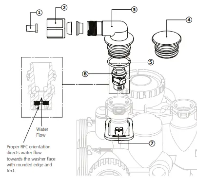
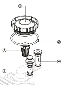
Fig. 7 – Injector Cap, Injector Screen, Injector, Plug and O-ring
| No. | Part Code | Description |
| 1 | WTV3176 | Injector Cap |
| 2 | – | O-ring, 135 |
| 3 | – | Injector Screen |
| 4 | WTV5640 | Injector Plug |
| 5 | WTV5580 | Injector, Blue (F) |
Replace the Backup Battery
- The battery (CR2032 coin) keeps the time in case of a power outage. The battery should be replaced annually or after extended periods without power.
- Reset the time if needed by following the instructions in the user guide for your model.
- If your system is backwashing only (no salt), then replace the weather cover to complete the service


Brine System Servicing [Softener Only]
- Isolate the water supply and release the pressure by opening an outlet after the system.
Note: If you have the optional bypass assembly, turn the handles so that they point toward each other. - Remove the injector cap. To remove the injector cap located on top of the valve, first remove the brine clip and the elbow fitting. Next use the Puretec WTV5180 spanner and multitool to remove the injector cap by turning anti-clockwise. If you don’t have the tool, a large set of multi grips or a strap wrench can be used with care.

- Flip the cap over and remove the injector screen located in the centre of the cap. Clean the screen and replace it back in the cap.
- Flush the injector feed port. With the injector cap still off, slowly open the inlet water so water is coming out of the injector feed port
as shown in the image. After a short flush, close the inlet water. - Remove the brine injector (labelled DN). To remove the brine injector, use the injector cap to lever the injector out as shown in the
image. - Check the injector is clean and free of debris and blockages.
- Re-insert the injector and push firmly to make sure it is all the way in.


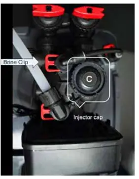
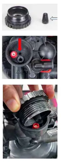
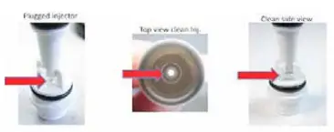
Fig. 8 – Water Meter, Meter Plug and Mixing Valve
| No. | Part Code | Description |
| 1 | – | 1″ Nut |
| 2 |
WTV5490 | Meter Assembly |
| 3 | Trubine Assembly | |
| 4 | O-ring, 215 | |
| 5 | – | Mixing Valve |
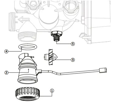
Fig. 9 – WTV5060 – 1″ Straight Adaptor, Male
| No. | Part Code | Description |
| 1 |
WTV5060 | 1″ Quick Connect Nut |
| 2 | Split Ring | |
| 3 | O-ring, 215 | |
| 4 | 1″ Straight Adaptor Fitting Body, Plastic, Male BSPT |
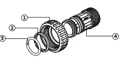
Fig. 10 – WTV5070 – 1″ Elbow Adaptor, Male
| No. | Part Code | Description |
| 1 |
WTV5070 | 1″ Elbow Adaptor Fitting Body, PVC, Male BSPT |
| 2 | 1″ Quick Connect Nut | |
| 3 | Split Ring | |
| 4 | O-ring, 215 |