![]()
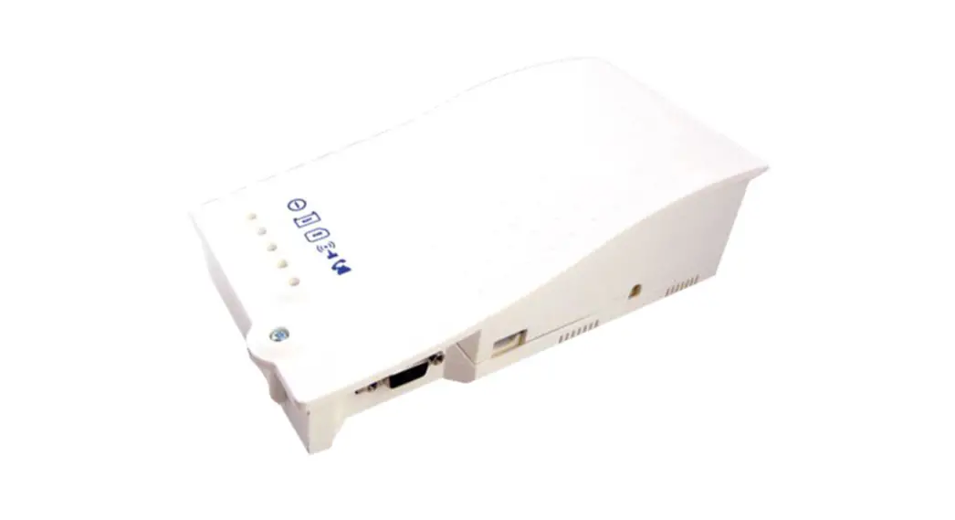
Installation & Operations Manual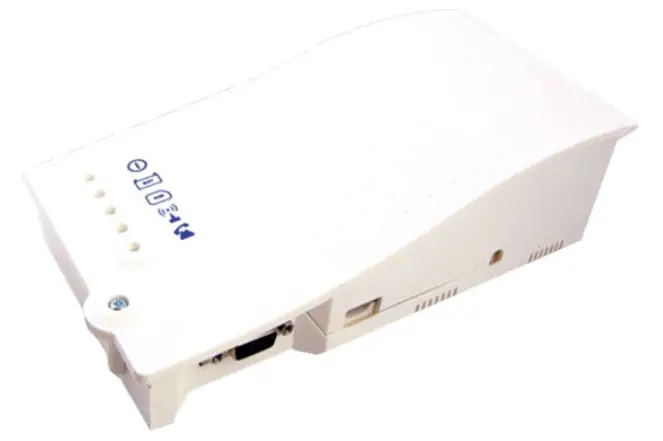 4G Cellular Gateway
2100-LTEGSM4-2 & 2100-LTEVER4-2
IMPORTANT NOTE: If using a Janus phone that is not equipped with external power, you must order Janus part # POWPK-12VC.
Items Needed
Included:
- 4G Cellular Gateway
- Antenna
- 2-year prepaid SIM card and plan (AT&T or Verizon)
Note: We recommend utilizing the provided antenna. If the signal is not strong enough in the intended installation location, we suggest moving the unit to a location with a stronger signal. If this is not feasible, you can try installing signal boosters to amplify the cellular signal throughout the building.
Not Included:
- Phillips screwdriver
Setting up the Cellular Gateway
- Open the Cellular Gateway by unscrewing the screw on the left side of the front cover with a Phillips screwdriver and gently pull up on the left side.
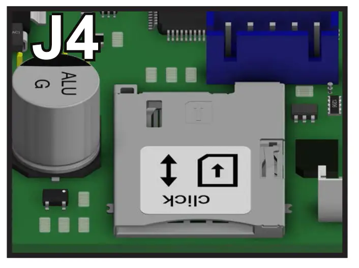
- Insert SIM card into J4 with the perforated edge first and the gold contact side facing downward. Push until you hear it click. If SIM card does not click into place the wrong size SIM card is being used.
Note: Do NOT use a nano or micro size SIM card with an adapter. The adapter edge can catch and cause permanent damage.
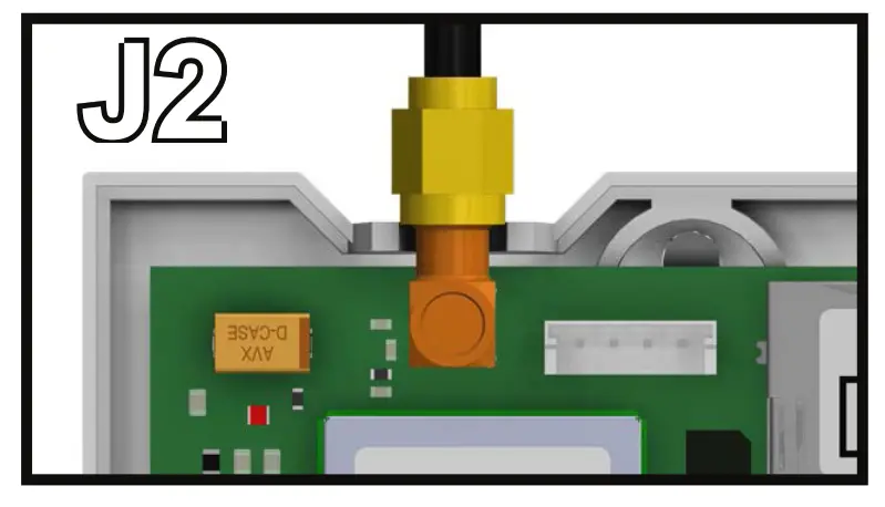
- Screw in the antenna to J2 on the Cellular Gateway and ensure it is completely tightened.

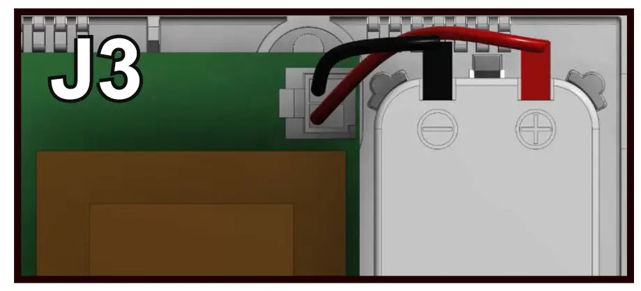
- Connect the battery to J3.

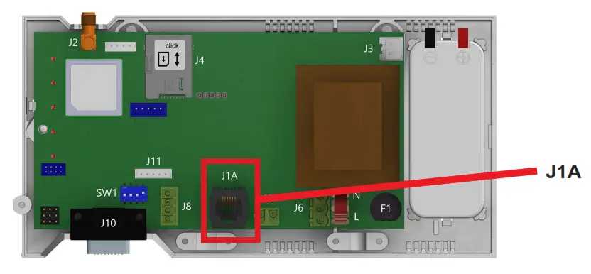
- Connect the phone(s). The Cellular Gateway provides an RJ11 jack or hardwired screw terminals for connecting devices. Do not exceed 1,000 feet.
RJ11 Jack:
a. Take a male RJ11 phone line cord or plug it into the J1A jack on the Cellular Gateway.
b. Plug the other end of the line cord into desired device. Hardwired Connection:
a. Gently remove provided 2 pin connector from J9 on the Cellular Gateway.
b. Screw the 2 wire connection from the desired device into the 2 pin connector. Pin 1 is tip (neutral) and pin 2 is ring (positive).
c. Plug the 2 pin connector back into J9.
- Wait for the LED lights to turn on. Check the SIM LED to make sure it is green or amber. If it is flashing red, check that the SIM card has been inserted correctly.
- A signal strength test is recommended. Check the signal strength by using the built-in network signal strength scanner. See the “Signal Strength Test” section on page 10 for more information.
- Plug the power cord into a 120vac power source or turn on the 120vac power source.
- Place the lid back on the top of the Cellular Gateway and fasten the lid with the screw.
- The RUN LED should change color from flashing amber to flashing green when the main power connection is made. If you see any other color, please consult the LED indication list.

 Hardwired Connection:
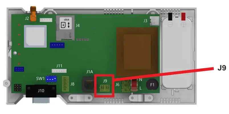
| RUN LED FLASHES GREEN | THE POWER SUPPLY IS OK |
| BAT LED IS ALWAYS ON | BATTERY IS OK |
| SIM LED IS AMBER | THE DEVICE IS CONNECTED TO THE NETWORK |
| COVERAGE LED IS GREEN OR AMBER | GOOD COVERAGE |
| SLIC LED IS GREEN | THE DEVICE IS IN STANDBY |
Connector Description
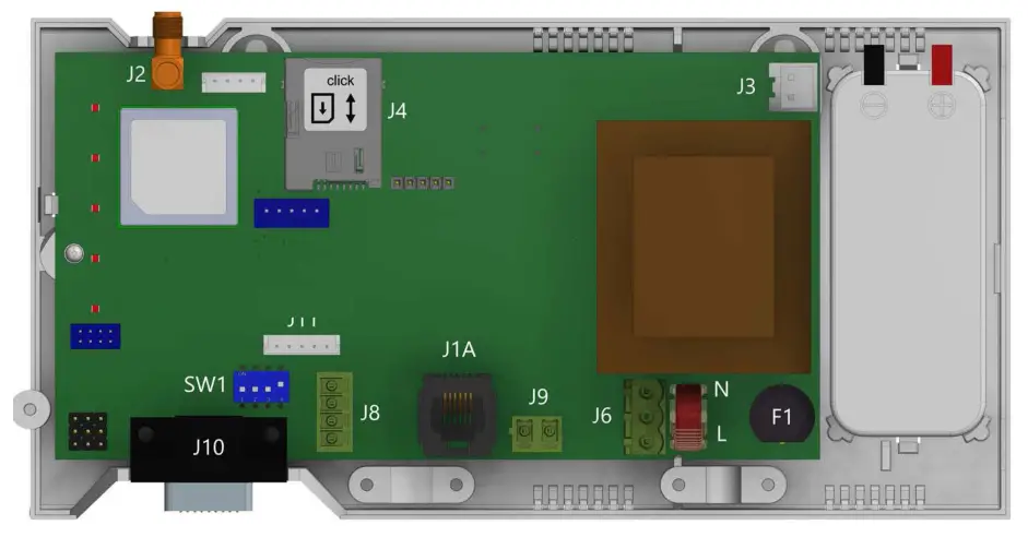
| DESCRIPTION | |
| J2 | EXTERNAL ANTENNA |
| J3 | BATTERY |
| J6 | POWER SUPPLY |
| J8 | CANBUS |
| J9/J1A | PHONE LINE |
| J10 | RS232 CONNECTOR |
Note: To access dipswitches and connectors, open the Cellular Gateway case by unfastening the front screw using a Phillips screwdriver and removing the lid.
Note: Connect to RS232 (J10) to use as a data pass-through. Distance limitation is approximately 1,000 feet. Actual numbers will vary based on the cable and gauge used.
J8 – CANBUS: CANBUS can only be used with specific products. See supplemental manual if applicable.
J2 – External Antenna: Connect the provided external antenna to the J2 connector. Only antennas approved by Rath/Janus should be used or the Cellular Gateway may not function properly and may be damaged.
J3 – BATTERY
| PIN | FUNCTION | SIGNAL |
| 1 | 12 | POSITIVE |
| 2 | GND | NEGATIVE |
J6 – POWER SUPPLY
| PIN | FUNCTION | SIGNAL |
| 1 | L | LIVE |
| 3 | N | NEUTRAL |
Supply Voltage: 100-240vac, 60/60 Hz
J9 / J1A – PHONE LINE (SLIC)
| PIN | FUNCTION | SIGNAL |
| 1 | L1 | TIP |
| 2 | L2 | RING |
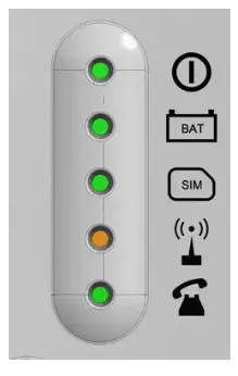
LED Indicators
The Cellular Gateway has five indicator LEDs that constantly report the device status. The indicators will be red, amber, or green. Each indicator will be fully on, fully off, or flashing. The table below provides an overview of what each colored LED indicates:
| RUN LED | OFF | ON | FLASHING | ||||
 | GREEN | AMBER | RED | GREEN | AMBER | RED | |
| CRITICAL SYSTEM ERROR | PROPER OPERATION (AC) | PROPER OPERATION (BAT) | RESTARTING SYSTEM | ||||
| BATTERY | OFF | ON | FLASHING | |||
 | GREEN | AMBER | RED | AMBER | RED | |
| OK | AC CHARGING | LOW | DAU BATTERY FAILURE (NO AC) | ERROR | ||
| SIM | OFF | ON | FLASHING | ||
 | AT MODEM | AMBER | RED | AMBER | RED |
| REGISTERED | OUT OF SERVICE/ INITIALIZING | ONGOING VOICE CALL | SIM ERROR | ||
| COVERAGE | OFF | ON | ||
 | GREEN | AMBER | RED | |
| OK | MEDIUM | LOW | ||
| SLIC | OFF | GREEN | AMBER | RED | FLASHING GREEN |
 | LOCAL LINE READY | INITIALIZING LOCAL LINE | LOCAL LINE OUT OF SERVICE | ||
| LOCAL LINE IN USE |
Wiring Diagrams
Rath SmartRescue System Wiring Diagram: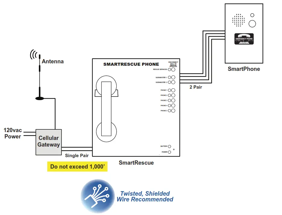
Rath Command Center System Wiring Diagram: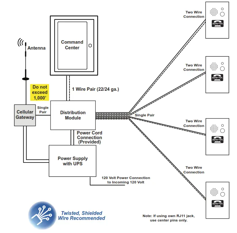
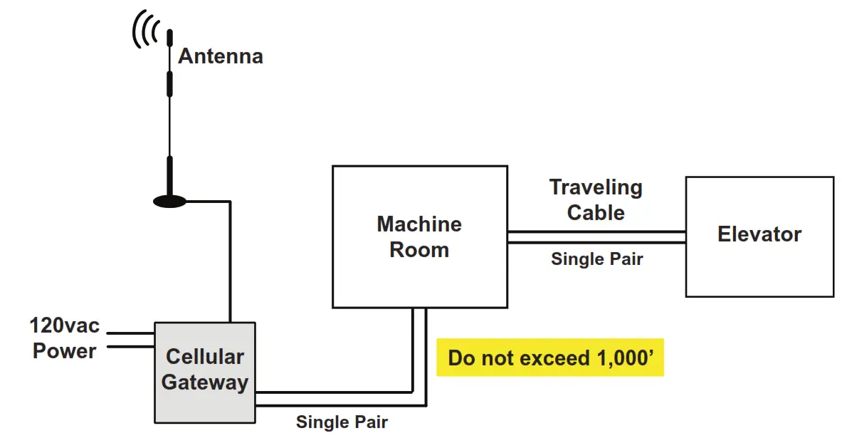
Janus Elevator Application Wiring Diagram: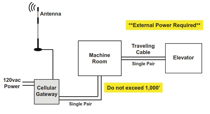
Janus EMS5 System Wiring Diagram: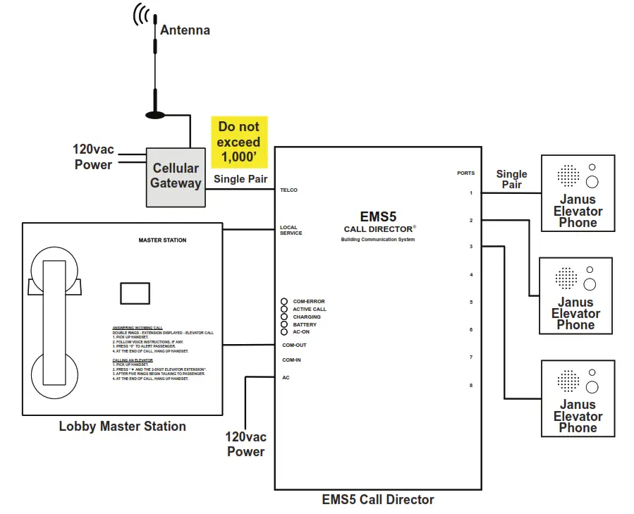
Appendix
Installation: This equipment is intended for installation in restricted areas by qualified personnel.
Environmental Conditions: This device is designed to be used indoors (32° F to 113° F with relative humidity between 20% and 80% not condensing). Sudden changes of temperature and humidity should be avoided. Cleaning and Maintenance:
Use a soft dry cloth. Do not use solvent or abrasive products.
Safety: Please read these safety instructions before starting the device.
- Do not expose this device to liquids or excessive humidity. This is an indoor device and is not waterproof.
- Do not expose this device to fire.
- Do not try to modify the device.
- Do not use this device in potentially hazardous areas or where there is risk of explosion.
- This device emits low levels of radio frequency when in operation.
Battery: This Cellular Gateway includes a NiMh 800mAh battery that allows it to keep functioning in the event of a main power failure. The battery provides 4 hours of talk time. The battery should be replaced every 4 years. Only install batteries authorized by Rath/Janus and only allow qualified personnel to replace the battery. The battery should be properly recycled and not disposed of with unsorted household waste. Please take all necessary precautions when changing the battery.
Voltage Rating:
Idle: 110-120v, 50/60Hz, current draw 40mA
Active: Current draw 80mA
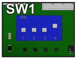
Signal Strength Test: LEDs on the front of the device will show the network signal level. To use the scanner function, turn the SW1 dipswitch to “ON” (verify that dipswitch 4 is also ON). All LEDs will turn off except for the battery. Within 2 minutes, the signal strength LEDs will appear.
Note: The signal scanner will indicate the best location for the device to receive signal. Network coverage will be based on local conditions.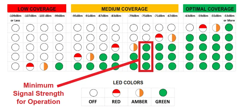
When finished, turn SW1 dipswitch 1 back to OFF. You can check the status of the power supply, battery, connection, coverage, or phone line (SLIC) at any time by referring to the LED indicators.
 WARRANTY 2
YEARN56 W24720 N. Corporate Circle Sussex, WI 53089 800-451-1460
www.rathcommunications.com
www.januselevator.com
RP8500DCPR
Ver. 7 07/22


